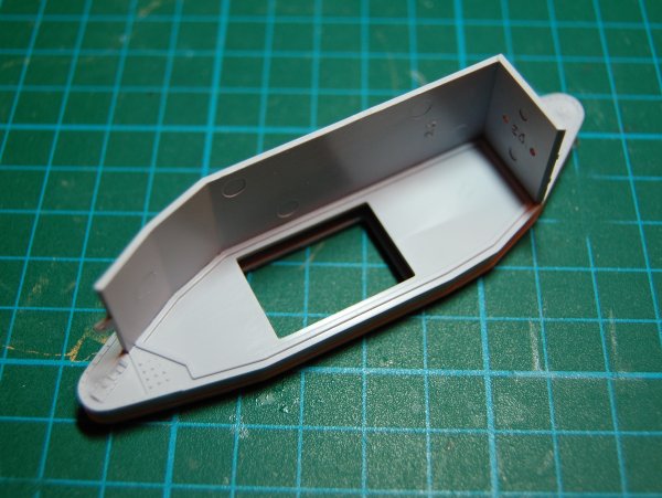
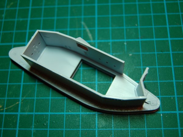
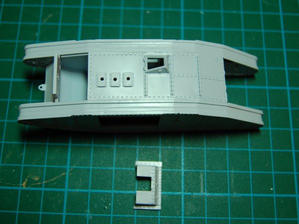
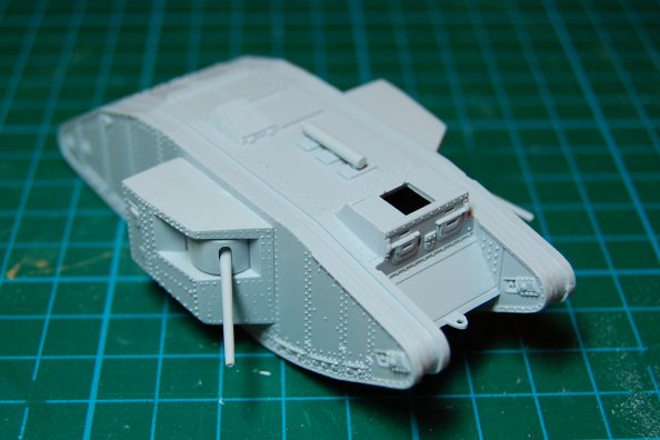
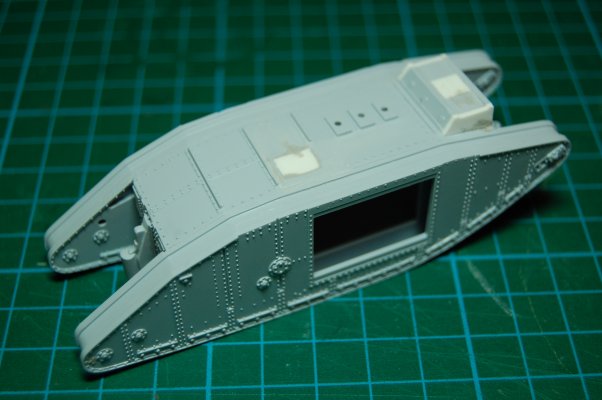
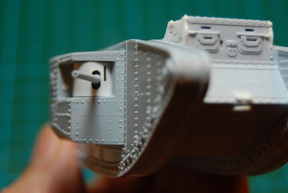
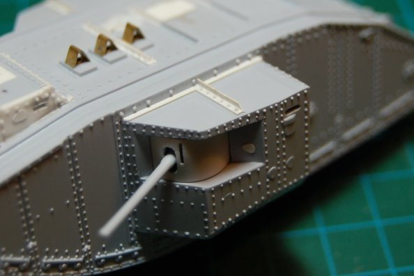
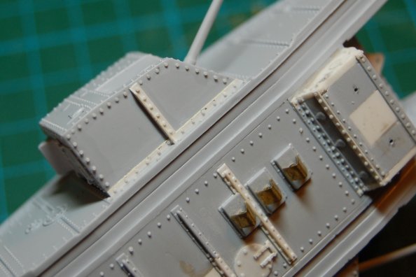
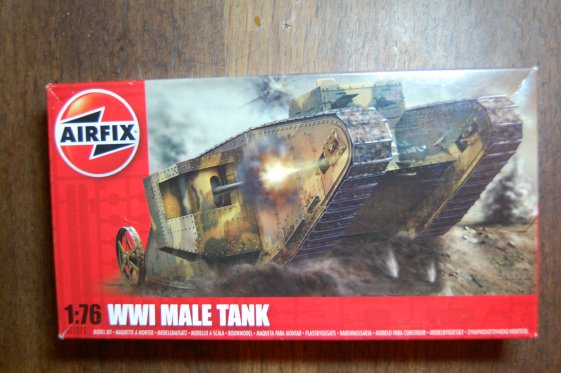
OK, at the risk of boring anyone, here is Airfix's "WWI Male Tank" - the re-release. No doubt anyone with a special interest in WW1 has built this kit before, but yes, it has just been re-released, and yes, I can't see any other photo of this kit on this site. So here it is. Interestingly, the box says it is made in India.
I never built this kit in the old days, but from photos elsewhere on the web, it is pretty evident that this is the same basic model as the previous release. I have seen it suggested that the mould has been cleaned up, and this would seem to make sense, as, to me, this doesn't look like a 40 year old kit. The detailing and moulding is crisp, there was little flash (compared to what I remember other old Airfix kits being like) and the fit of the parts was mostly very neat. So that's all good.
What isn't so good is that, since the kit is essentially the same, the same strange situation exists as to what this actually is meant to represent. This is very well documented on the Landships site.
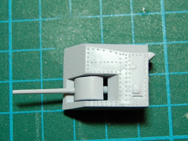
I started off having not bothered to read any of this and just started building. Here is a sponson with a not very nice looking gap which appears if you have the gun pointing straight ahead. My solution will be to have the gun pointing out at an angle from the hull.
Here is the hull fitting together very nicely.
The sides on, and just about to fit the roof of the cab:
To demonstrate the nice fit of the parts, here are the sponsons just sitting in the hull with no glue. The exhaust pipe has been added - as most are probably aware, this is wrong for a Mk1, as is the width of the cab and the roof hatch. The only detailing added so far is drilling out the gun barrels.
I'll post some more later on the changes which this kit kind of obliges you to make if you want anything half way authentic.
Right now I am off to do some more riveting.
Hosted by Darren Baker
Airfix "WWI Male Tank" Mark 1
firstcircle
England - South East, United Kingdom
Joined: November 19, 2008
KitMaker: 2,249 posts
Armorama: 2,007 posts
Joined: November 19, 2008
KitMaker: 2,249 posts
Armorama: 2,007 posts
Posted: Wednesday, October 21, 2009 - 10:25 AM UTC
retiredbee2
Florida, United States
Joined: May 04, 2008
KitMaker: 757 posts
Armorama: 518 posts
Joined: May 04, 2008
KitMaker: 757 posts
Armorama: 518 posts
Posted: Wednesday, October 21, 2009 - 11:25 AM UTC
I am totaly ready for this one in 35 th scale.........Al
firstcircle
England - South East, United Kingdom
Joined: November 19, 2008
KitMaker: 2,249 posts
Armorama: 2,007 posts
Joined: November 19, 2008
KitMaker: 2,249 posts
Armorama: 2,007 posts
Posted: Thursday, October 22, 2009 - 10:26 AM UTC
There, I knew I was being boring . . . sorry, this is the same old 1/76th one.
The unglued sponsons were put to one side and the exhaust pipe removed. The raised hatch in the hull roof was drilled and cut out, then blanked off with plastic card and filler, and the hole for the hatch in the driver's cab was filled in the same way.
Also, the cab has to be wider, so a layer of plastic card was also laminated to each side of the cab. I just took the card thickness as being the correct thickness rather than attempting to measure anything, and in fact, the cab cannot be the full width of the hull as some clearance is needed for the tracks. These side panels were cut slightly over sized, then filed and sanded down to match the profile of the existing cab.
Briefly, this cab width issue is due to wider tracks on later marks necessitating a narrower cab to allow clearance.
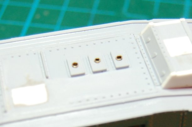
I made small exhaust outlets from brass sheet rolled around a drill bit and forced into the existing holes. Must admit they don't look quite even, but once the next bit goes on I don't think it is noticeable.
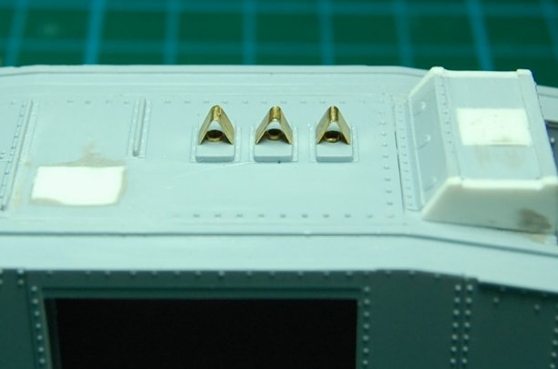
On top of the exhaust pipes go some covers, again made from brass sheet. Hmm, maybe they're not all exactly even either, but, maybe that doesn't matter.
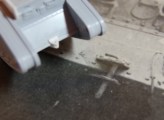
The tab-like tow hook was removed and replaced with something more like the original - two plates, one above and one below the joint of the hull nose. Note that they don't touch, but a pin just drops through, allowing an towing eye to be attached. After searching the web for a really clear photo of this part, and not finding one, I managed to find one in a book that I 've had for years...
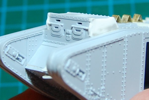
Having added the extra width to the cab, there's a bit of tidying and detail to be done on the outside edges of the two hatches in the front of the cab. The arrangement that I think is used for opening the flaps needs to be moved to the edge of the cab. I removed the existing detail then recreated it further out. Must say that detail this small I find pretty hard to make. Essentially, each of the two white vertical parts at the front edge of the cab started out as a small strip of card cut to the right length then cemented on to the cab. It was then carved and sanded down into the curved profile. There are some rods that connect those hinge pieces to the driver's hatches, and these were simply lengths of 0.5mm styrene rod.
I'll tell you about the riveting later, if you can stay awake.
adamsmasher
Illinois, United States
Joined: June 27, 2009
KitMaker: 192 posts
Armorama: 54 posts
Joined: June 27, 2009
KitMaker: 192 posts
Armorama: 54 posts
Posted: Thursday, October 22, 2009 - 11:25 AM UTC
Looking good Matthew.
I have the Emhar 1/72 Mk IV "Male" kit in my stash. Maybe not the same thing, but I can steal glean tips from this (hey... I stayed awake, too).
bpunchy
Western Australia, Australia
Joined: February 22, 2009
KitMaker: 366 posts
Armorama: 199 posts
Joined: February 22, 2009
KitMaker: 366 posts
Armorama: 199 posts
Posted: Thursday, October 22, 2009 - 11:53 AM UTC
Hey Matthew , this is so boring I've subscribed to your thread . Ha . Looking good so far . There was a link to images of some restoration of these in Russia in forums a little while ago . Does any manufacturer make 1:35th scale WW1 tank kits that are currently available ? I look forward to seeing where you go with this build .
adamsmasher
Illinois, United States
Joined: June 27, 2009
KitMaker: 192 posts
Armorama: 54 posts
Joined: June 27, 2009
KitMaker: 192 posts
Armorama: 54 posts
Posted: Thursday, October 22, 2009 - 12:25 PM UTC
Hi Brian.
Emhar make about 5 different 1/35 WWI kits:
British "Male" Mk.IV
British "Female" Mk.IV
British Medium A Whippet
Tadpole Mk.IV Male
Mk V "Hermaphrodite"
There may be others, but those are the ones I know of off the top of my head. Never built them myself, though I've seen a number of complaints about them.
spongya
Associate Editor
Budapest, Hungary
Joined: February 01, 2005
KitMaker: 2,365 posts
Armorama: 1,709 posts
Joined: February 01, 2005
KitMaker: 2,365 posts
Armorama: 1,709 posts
Posted: Thursday, October 22, 2009 - 12:44 PM UTC
Hey, I'm building this kit, too
I'm following this thread.
tread_geek
Ontario, Canada
Joined: March 23, 2008
KitMaker: 2,847 posts
Armorama: 2,667 posts
Joined: March 23, 2008
KitMaker: 2,847 posts
Armorama: 2,667 posts
Posted: Thursday, October 22, 2009 - 12:57 PM UTC
Matt, wonderful, fantastic and go for it. Don't put yourslf down. Any submission of a build is great. Can't wait to see more. Chin up, and thanks for sharing. Oh, you should post this in the Braille Scale forum for those that appreciate this size.
Cheers,
Jan
Cheers,
Jan
bpunchy
Western Australia, Australia
Joined: February 22, 2009
KitMaker: 366 posts
Armorama: 199 posts
Joined: February 22, 2009
KitMaker: 366 posts
Armorama: 199 posts
Posted: Thursday, October 22, 2009 - 08:55 PM UTC
Hey Matthew , thanks for the info about 1:35 scale Mk1's keep up the build posts mate .
weathering_one
Ontario, Canada
Joined: April 04, 2009
KitMaker: 458 posts
Armorama: 456 posts
Joined: April 04, 2009
KitMaker: 458 posts
Armorama: 456 posts
Posted: Friday, October 23, 2009 - 05:59 PM UTC
This build is "tres" cool, Matthew. I've seen this Airfix kit a few times but never felt an urge to buy or build it. I think you might be changing that opinion. Maybe place it on a mounting as a memorial or something might be appropriate.
I liked this,
AJ
I liked this,
AJ
adamsmasher
Illinois, United States
Joined: June 27, 2009
KitMaker: 192 posts
Armorama: 54 posts
Joined: June 27, 2009
KitMaker: 192 posts
Armorama: 54 posts
Posted: Friday, October 23, 2009 - 07:51 PM UTC
Quoted Text
This build is "tres" cool, Matthew. I've seen this Airfix kit a few times but never felt an urge to buy or build it. I think you might be changing that opinion. Maybe place it on a mounting as a memorial or something might be appropriate.
I liked this,
AJ
This is totally irrelevant and off-topic, but I like your initials... haha.
firstcircle
England - South East, United Kingdom
Joined: November 19, 2008
KitMaker: 2,249 posts
Armorama: 2,007 posts
Joined: November 19, 2008
KitMaker: 2,249 posts
Armorama: 2,007 posts
Posted: Sunday, October 25, 2009 - 04:32 AM UTC
Thanks for the interest. I wondered if this kit had just been done to death elsewhere, you see.
I am off on holiday for a week, so will post more on my return. I'd better go and pack...
firstcircle
England - South East, United Kingdom
Joined: November 19, 2008
KitMaker: 2,249 posts
Armorama: 2,007 posts
Joined: November 19, 2008
KitMaker: 2,249 posts
Armorama: 2,007 posts
Posted: Thursday, November 05, 2009 - 09:33 AM UTC
Rivetting isn't it? Except, this time it is. If you follow the link to the Landships site I put in the first post, there is an article on the rivets on this kit, saying basically there are too many of them on the sides. Like most modellers of this kit I will completely ignore that problem. There are however places where there are rivets missing on the original kit, also some were damaged or removed during my work on the roof, and the changes made require some more to be added.
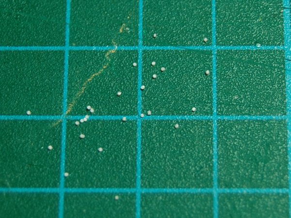
The rivets moulded on the kit (by the way, I never realised until this evening that Americans spell it "molded"...) are tiny. There are various ways of attempting to replicate rivets, but I just went for 0.5mm rod. They are bigger than the originals, but at least I can get them in the right place, and they have a regular look to them - I am hoping . . . I am fully prepared to realised once I paint it that it is a disaster.
I made tiny slices of rod with a brand new blade, and glued them on with liquid cement, applying them with the point of the blade. Forget tweezers. You need enough glue to keep them on but not so much that they melt. Getting the slices of regular size isn't that important, as providing they are fixed on properly, they can be sanded down to a regular profile later - preferably several hours later.
This is the line of rivets added to the top front of the cab roof, missing from the kit:
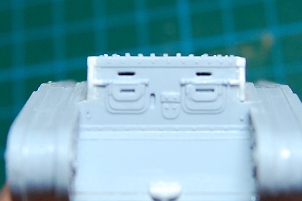
The different heights are apparent, but they were sanded down.
Four rivets added to each tow bracket :
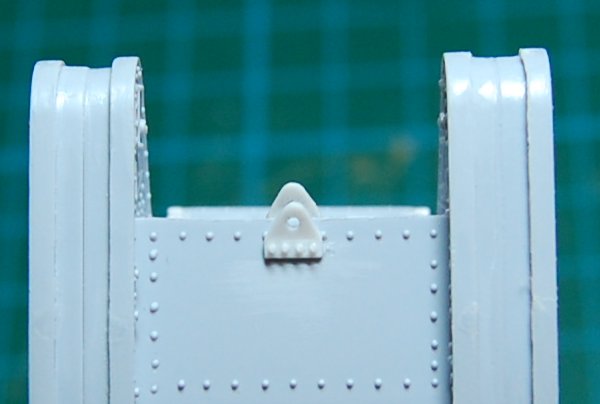
As I said, I'm not too sure that, when this is painted, my 0.5mm rivets might look very oversize compared to the moulded on ones, but in this photo, they don't look that out of size. I was thinking, 0.5mm x 76 = 38mm, which is definitely too big, but it isn't that wild - to me anway. I think it is the texture and look of the rivets that is the important thing, and it is probably better to have big rivets than no rivets.
The extra details to be added to the roof. With the raised hatch removed and blanked out, there are some rivetted plate joints to be added in that area. I made them from microstrip. The one to the left of the deleted hatch needed repairing, the one to the right was extended to be the full width, and match the others, and an entirely new one added in between the rear and middle exhaust outlet.
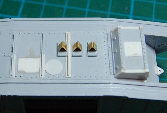
Also in the above photo is the start of the circular hatch.
In the next one I have added the rivets both to the new joints and to the hatch, and the hatch also has a hinge.
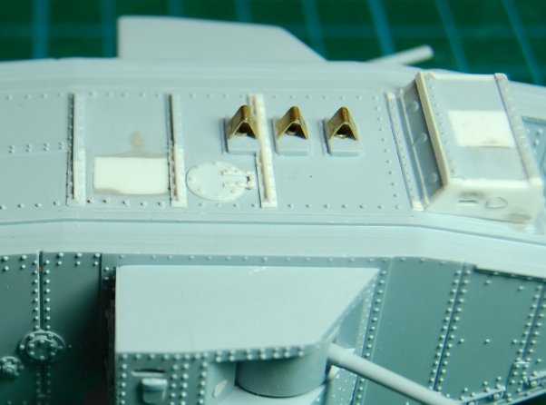
In fact this is a couple of days work later... notice that another strip has been added to the upper rear of the cab. Basically all the angled joints were covered over with extra plate rivetted on, and some of these are omitted on the kit. Looking at the front of the cab roof you should be able to see that the rivets have now been equalised and look a bit more subtle.
The sides of the cab have had some detail added. There is a vision port, which I located incorrectly on the first attempt hence the grey filler smudge at the top. This was drilled out with a series of 0.4mm holes which were then joined together. It OBVIOUSLY would have been better to have made these first before attaching the plates to the side of the cab - but... I always think I'm just going to build it quickly and not bother with all the detail. But then I go back and elaborate. Also on the side of the cab and on the sponson is the covers for the pistol port or whatever they are.
To come is the mystery that is the steering limber, and more of my backward detailing efforts.
adamsmasher
Illinois, United States
Joined: June 27, 2009
KitMaker: 192 posts
Armorama: 54 posts
Joined: June 27, 2009
KitMaker: 192 posts
Armorama: 54 posts
Posted: Friday, November 06, 2009 - 08:17 AM UTC
Thanks for the update, Matthew. I just started working on the Emhar version of this kit, thought I'm just building it OOB.
edit: I forgot that the Emhar kit is a Mk. IV, not a Mk. I, so it's not quite the same thing (also, it's 1/72 instead of 1/76 - not that it's a great difference).
tread_geek
Ontario, Canada
Joined: March 23, 2008
KitMaker: 2,847 posts
Armorama: 2,667 posts
Joined: March 23, 2008
KitMaker: 2,847 posts
Armorama: 2,667 posts
Posted: Friday, November 06, 2009 - 09:21 AM UTC
First rate nitpicking Matthew. And my SWMBO thought I was bad at excessive detailing. At the rate you are going I can see another Mk 1 with fully detailed interior or perhaps functioning running gear. Absolutely intriguing build.
Cheers,
Jan
Cheers,
Jan
firstcircle
England - South East, United Kingdom
Joined: November 19, 2008
KitMaker: 2,249 posts
Armorama: 2,007 posts
Joined: November 19, 2008
KitMaker: 2,249 posts
Armorama: 2,007 posts
Posted: Wednesday, November 11, 2009 - 09:18 AM UTC
Adam, remember to let us see some pix of your Mk IV build. I was trying to be not too nitpicky, but last night I did start to think about all over rivet removal. Some did go...
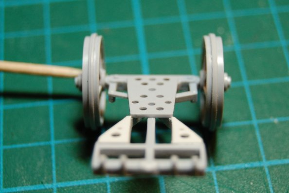
I was reading about the limber on the Landships site, and it said - "it's plain what you need to do to detail the limber from this picture." I thought, no, it isn't. I don't know if this applies to the Mark IV, but it seems like there just aren't many photos of Mk Is, and since the limber was rejected after a short while, even fewer of that exist.
So as usual here, I built the limber, then detailed it afterwards. Below you can see the thinned down left hand steering rod, carved off with a blade. Also, blurry, the drilled triangular plates.
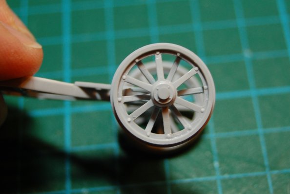
Rivets added to where the spokes meet the rim - each spoke on both sides need to be done.
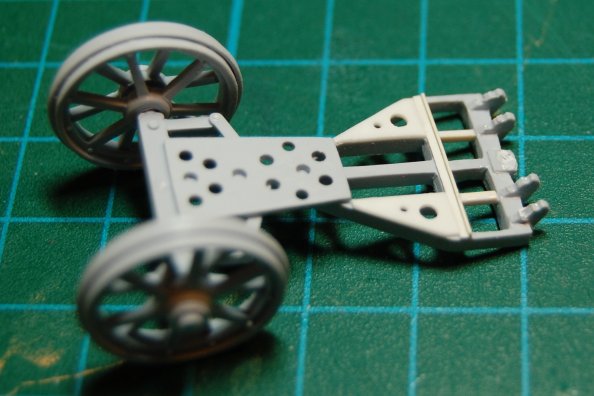
Here the limber is more or less done. Better view of the triangular plates with the two odd holes drilled. Behind that there was a narrow L-section strip added crossways, and two additional members added longways between the existing three. I don't really know if any of this is really right, but it seems more right than the kit.
firstcircle
England - South East, United Kingdom
Joined: November 19, 2008
KitMaker: 2,249 posts
Armorama: 2,007 posts
Joined: November 19, 2008
KitMaker: 2,249 posts
Armorama: 2,007 posts
Posted: Wednesday, November 11, 2009 - 09:37 AM UTC
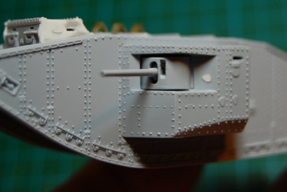
Once I thought I'd nearly finished, then I went backwards some more. Next to each gun is a narrow sighting slit in the shield completely missing from the kit. Obviously it needs to look like a hole all the way through but the curved plastic of this part is quite thick. If I'd done it before building the sponsons I might have been able to get the hole drilled nice and neatly, but the first attempt didn't look too straight and was also too wide. So I had to get drastic... this picture shows the hole enlarged even more, for reasons that will be explained.
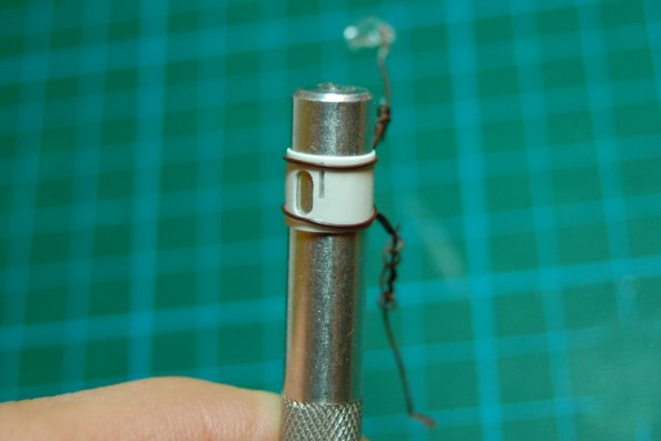
The only way left was to make a kind of mask, from very thin plastic card. Spent two hours making one of them then realised it was so thin at the top edge that I needed to bend it first before attaching it so that the pastic didn't crack. So here it is wired to a knife handle:
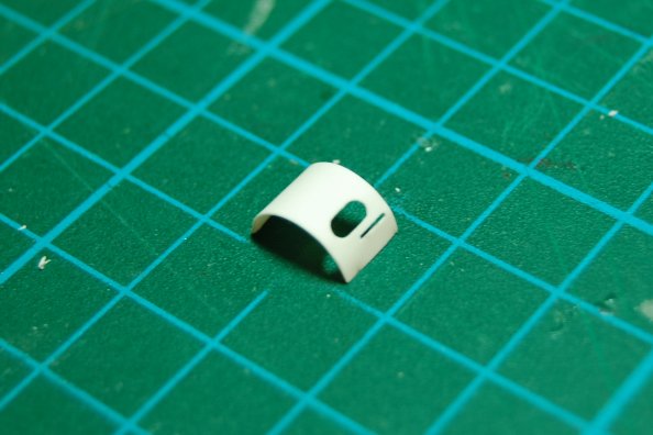
which was then held in steam from the kettle, resulting in this:
In fact this is the one for the other side, but it came out better.
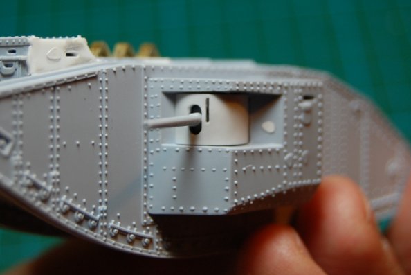
They were mounted over the guns, the edges tucking inside the sponson, and cemented on. The holes underneath was cut out oversize to provide a dark space behind the new narrow slits going on top.
Notice that the sighting slit is to the right of the gun on both sides, so they aren't symmetrical as it were. Here is the other side. To be honest, this was even more of a pain because the shield wasn't set as far back into the sponson, so the new layer stood out beyond the sponson, which looked bad. I had to remove the sponson and detatch the gun enough to move it back a mm or so; in fact it kind of rotated inwards a bit. Never mind, in the end I think this one turned out better.
Also, these masks have helped reduce the gaps between the shield and the aperture they are mounted in.
This is in fact a really enjoyable model to build. There's something so solid about the chunky little lozenge - it would have been nice to add some weight inside the hull to bring it up to scale weight - and except on the limber, not a single wheel!
Beaver2206
England - West Midlands, United Kingdom
Joined: November 03, 2007
KitMaker: 61 posts
Armorama: 56 posts
Joined: November 03, 2007
KitMaker: 61 posts
Armorama: 56 posts
Posted: Wednesday, November 11, 2009 - 10:09 AM UTC
I have to make a Normandy cowl for a cromwell soon and will definately try the steaming technique.
many thanks
Stu
many thanks
Stu
firstcircle
England - South East, United Kingdom
Joined: November 19, 2008
KitMaker: 2,249 posts
Armorama: 2,007 posts
Joined: November 19, 2008
KitMaker: 2,249 posts
Armorama: 2,007 posts
Posted: Friday, November 13, 2009 - 12:53 PM UTC
I promised lots of sleep-inducing rivets:
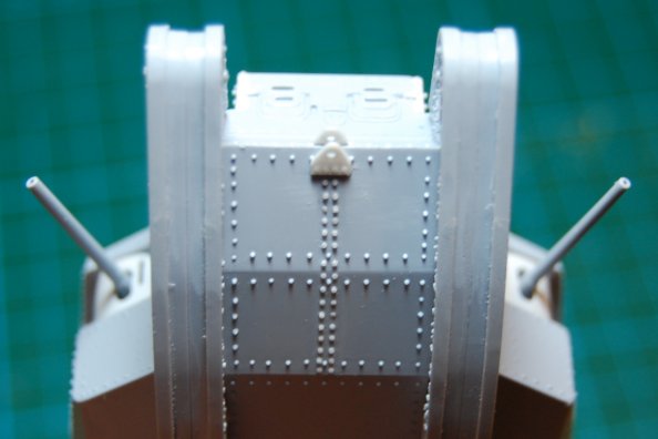
The many tiny kit rivets along the body above the sponson were removed and replaced with fewer bigger rivets - seven evenly spaced with an extra one next to the first and last. They look bigger in photos, and wider spaced; might be something to do with the fact that the sponsons were removable for transport purposes - but I don't know for sure. I wonder if they might really be bolts.
The kit gives no details at all to the top of the sponson. There are a few photos that show, albeit an angled view, some of the detail that should be there. A strip was added to the top of the sponson where it joins the hull. Also added was an L-profile strip perpendicular to the hull, which ends with a 45 degree angled vertical end. This was also, inevitably, rivetted on:
Then more rivets were added all the way around the edge of the top of the sponsons. These were spaced every 1.5mm; obviously I marked these out with a pencil and ruler:
Another missing piece of kit detail is on the lower nose plates, under the two bracket, where there should be two lines of rivets down the centre of the plates. They were duly added:
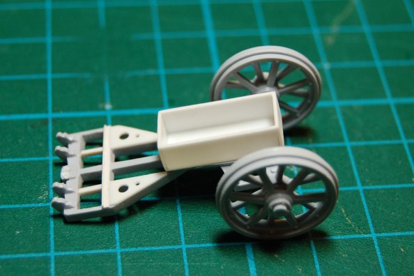
Some of these tanks carried a specially made wooden box on the limber in which to carry stores, possibly fuel, although presumably not in combat, but also tow cables, and possibly extra tins of grease?
So to provide a bit of a rest in between the rivetting, I made the box:
Apparently they used to sometimes take a couple of carrier pigeons with them in the tanks. There is the Incredible story of one tank being disabled and attacked by German troops where the crew released a pigeon to take a message back to their lines; as a result a rescue party was dispatched which managed to save the crew and recover the machine. If I'd read that earlier I might have built this with that top hatch open - just enough for a hand and a bird. . .
adamsmasher
Illinois, United States
Joined: June 27, 2009
KitMaker: 192 posts
Armorama: 54 posts
Joined: June 27, 2009
KitMaker: 192 posts
Armorama: 54 posts
Posted: Friday, November 13, 2009 - 06:04 PM UTC
Fantastic attention to detail Matthew. I don't think I have the stamina to keep my focus that long.
I set aside my Mark IV build to work on my contribution to the ACUTR campaign:
https://armorama.kitmaker.net/forums/148577&page=1
Also, the one of the tracks split (and not on a seam) and pissed me off... haha.
I set aside my Mark IV build to work on my contribution to the ACUTR campaign:
https://armorama.kitmaker.net/forums/148577&page=1
Also, the one of the tracks split (and not on a seam) and pissed me off... haha.
firstcircle
England - South East, United Kingdom
Joined: November 19, 2008
KitMaker: 2,249 posts
Armorama: 2,007 posts
Joined: November 19, 2008
KitMaker: 2,249 posts
Armorama: 2,007 posts
Posted: Friday, November 20, 2009 - 11:57 AM UTC
Quoted Text
I don't think I have the stamina to keep my focus that long.
I'm not sure I really do either, but for anyone who can stay with it, the actual construction is almost there.
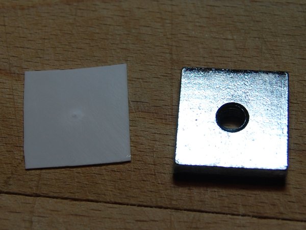
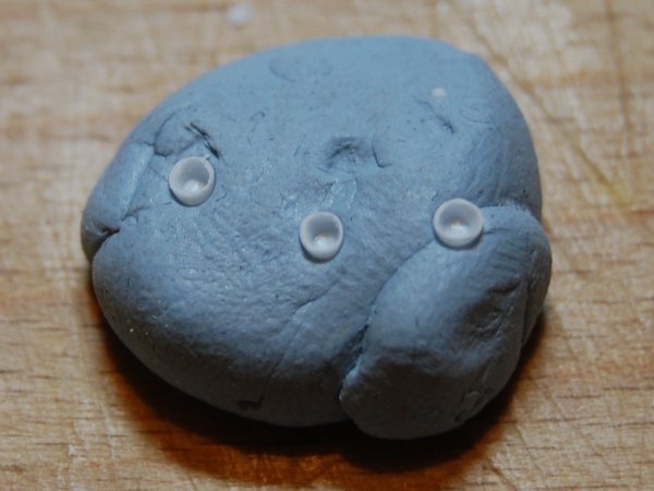
Headlamps. No doubt these things lasted about two seconds in action, but they did have them, and they are omitted from the kit. I looked through the meagre spares box but there were no pairs that looked right. I also wanted at least one to be just the shell, with the lens and bulb blown out, so after pondering a while (mostly while at work probably) I came up with the idea of some rudimentary moulding.
The thing on the left is a square of 0.5mm poly sheet, on the right is a bolt thing off a roof rack:
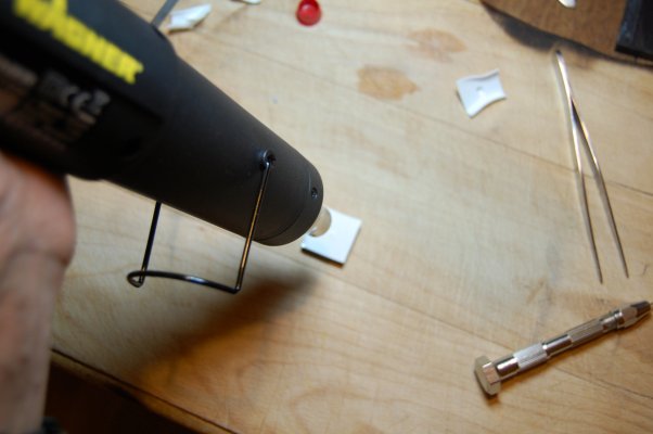
Heating up the plastic with a Wagner heat gun:
I never knew I wanted one of these until I saw it in TK Maxx. As I said, this is rudimentary moulding: I tried holding the plastic down with another one of the bolts on top, like a sandwich, to stop it from curling up, but it shielded it from the heat too much. The good thing about this heat gun is you can stop it from getting too hot, so the plastic doesn't actually melt too much and you don't get any fumes.
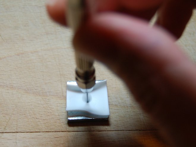
When soft, a 0.9mm drill bit, mounted backwards in the chuck, was pushed gently into the plastic, through the hole in the bolt:
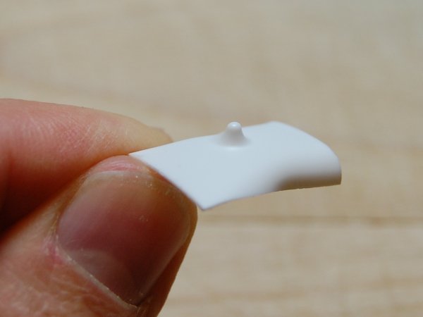
The result::
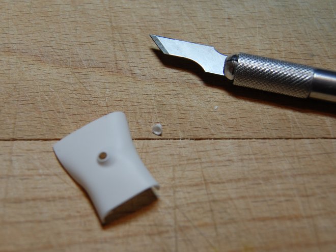
Chop:
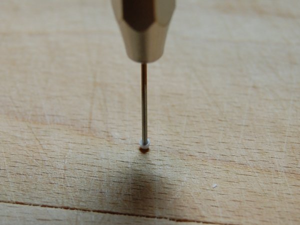
Sanding it down was difficult as it is not just small but round and has a tendency to pop out of tweezers and fly across the room. The open edge was sanded down by pressing it down on to the emery paper and circulating it with my fingertip, while the sides were thinned down and made more regular by holding it down with the same drill bit, then sanding around the edges:
Making two exactly the same is difficult, so I made three and picked the two that were nearest in size:
I probably could have made about ten before I got two that looked totally identical, but they'll do.
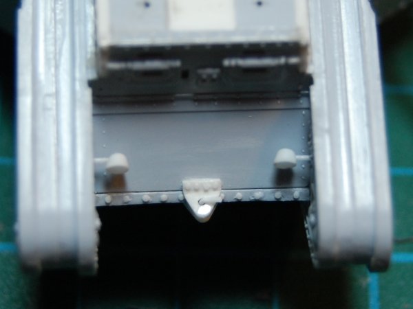
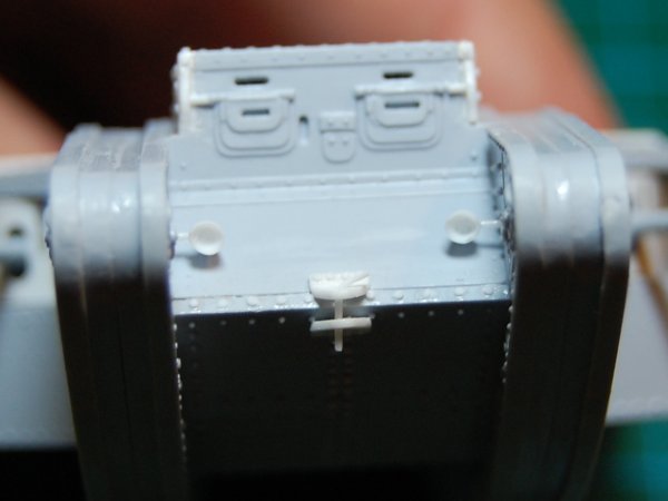
Small holes were drilled in the sides of the shells, using a brand new pointed blade - a drill bit just couldn't get the purchase on such a tiny rounded shiny thing - as well as in the inner sides of the track horns (so called) above the nose. The lamps are mounted on lengths of 0.5mm rod. A bit thick really, but never mind.
At some point during painting, I think I will fill one of them with epoxy for a lens, and leave the other one as it is. I think the fact that they are not exactly the same size might then be less noticeable.
Also added here is the bar that drops through the towing eyes, no doubt there is a special name for that bar, but I don't know what it is.
firstcircle
England - South East, United Kingdom
Joined: November 19, 2008
KitMaker: 2,249 posts
Armorama: 2,007 posts
Joined: November 19, 2008
KitMaker: 2,249 posts
Armorama: 2,007 posts
Posted: Friday, November 20, 2009 - 12:11 PM UTC
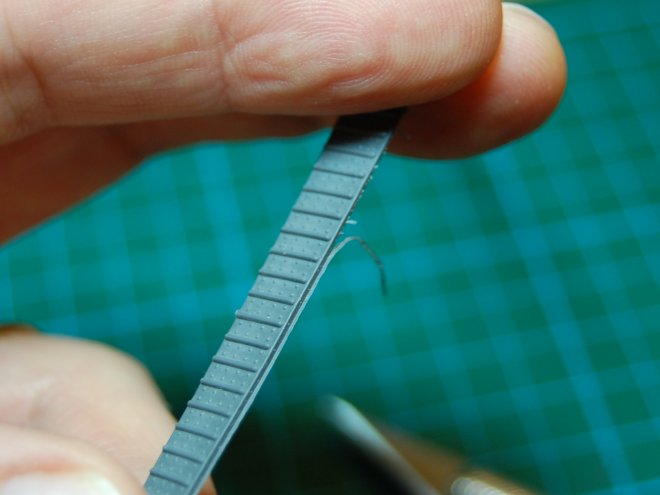
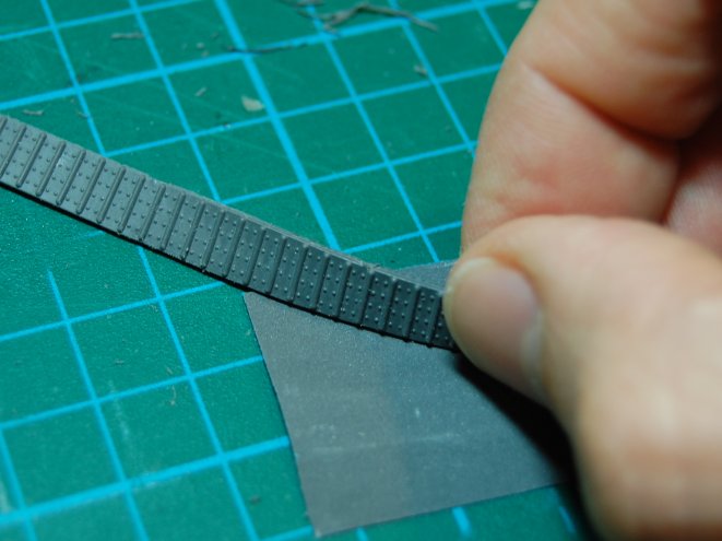
The tracks that are provided are very rubbery, not vinyl, and come with some horrible flash on them as well as little pips where they are joined together and have to be cut apart. The way the tracks are profiled makes getting the bit you want to trim off very difficult to get flat on a surface.
Eventually I tried kind of scraping at the side of the track with a sharp blade, which did kind of work in that the flash came off, but it left a slightly hairy roughness behind:
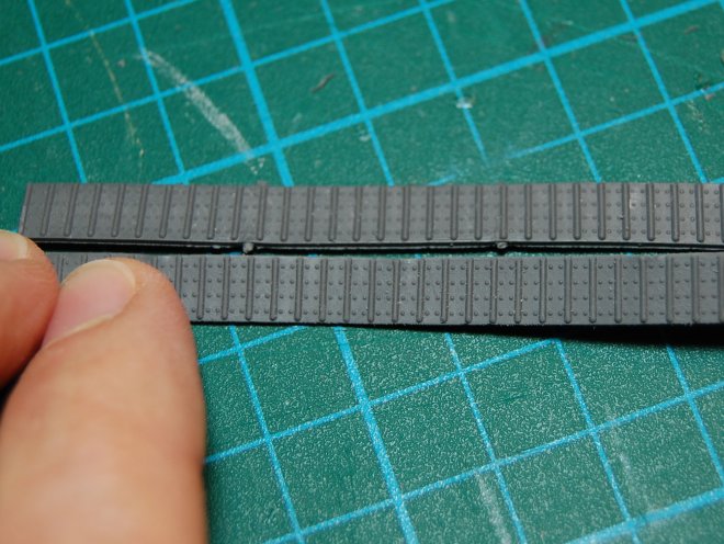
Thinking at first it was a stupid idea, I thought I might as well try emery paper on it. 600 or 900 or whatever it was slightly improved it, but was too abrasive and just created smaller hairy bits. But the finest grade I had, 1500, worked:
It just takes a little patience and you can get rid of the flash and the dimples. Here is the cleaned up one compared with the other one:
Now I'm wondering how to paint them. I'm thinking I need to mostly paint the tank first, and the tracks separately, then attach them for the weathering. Any tips for painting soft rubbery tracks? I wondering if I need to undercoat in some special way . . . PVA?? Or shall I just attach them now and do the whole thing, including the tracks, in primer?
adamsmasher
Illinois, United States
Joined: June 27, 2009
KitMaker: 192 posts
Armorama: 54 posts
Joined: June 27, 2009
KitMaker: 192 posts
Armorama: 54 posts
Posted: Saturday, November 21, 2009 - 06:37 AM UTC
Lookin' good, Matthew!
I've never painted rubber tracks, but I'd probably just prime and paint them as you would vinyl tracks if it were me. It's always been easier in my opinion to paint the tracks off of the tank, and then put them on later before weathering. Touching up glue spots with a brush is quick and then you cover everything with weathering.
firstcircle
England - South East, United Kingdom
Joined: November 19, 2008
KitMaker: 2,249 posts
Armorama: 2,007 posts
Joined: November 19, 2008
KitMaker: 2,249 posts
Armorama: 2,007 posts
Posted: Thursday, November 26, 2009 - 09:09 AM UTC
I'm glad you said that, now I can put off dealing with them. The tracks have now been primed and it seemed to go on OK.
Quick update for those who etc. etc. . . .
The construction finished:
One additional mod not previously mentioned was the removal of the central joint and rivets on the second roof panel, the one before the blanked off hatch. In photos it looked like it wasn't there, so I got rid of it!
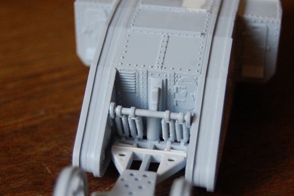
The way the limber attaches seemed a bit odd. I'm not convinced I did it as intended. That vertical hydraulic cylinder thing that sticks out the back looks like it is kind of upside down, but can't be fitted the other way. Then I needed to remove some peg sticking out the bottom of it in order to get it to fit into the centre of that horizontal beam. That bracket with the four springs on it fits in without any cement and swivels, which enables it to be moved to exactly the right angle when it comes to offering up the limber, a real blessing. Notice the springs kind of angle in downwards.
White car primer:
This was the usual first coats, then do some more filling and sanding where the old hatches were filled in on the roof and all the imperfections were highlighted. Came out OK after the subsequent coats.
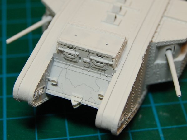
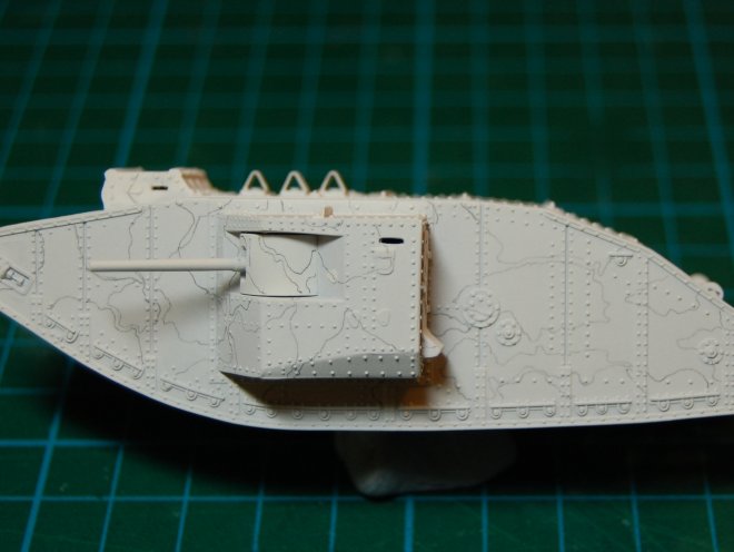
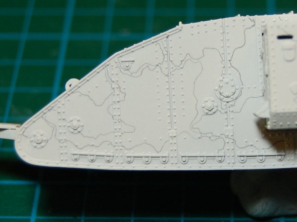
Also the camouflage sketched out in pencil:
There are various camouflage finishes possible on these early tanks before they all went khaki or brown, and it's all quite confusing. The best summary I found on this guide sheet for Black Lion Decals' WWI mk I - III tank markings: Black Lion
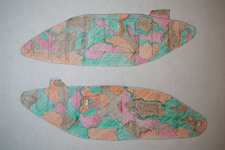
I am planning to go for the scheme described here as B1, which is the first camouflage attempt. This is the one with pink and no black . . . It's not very clear what any of the shades really are, and photos are not only in black and white, but the style seems to vary from tank to tank. In some ways that makes it difficult to get right, but I guess it also allows leeway, because no-one is quite sure what right is.
I tried to follow markings from several photos of different machines and then sketched it out to try to get it clear in my head; these aren't the right colours of course, but it gives an idea:
spongya
Associate Editor
Budapest, Hungary
Joined: February 01, 2005
KitMaker: 2,365 posts
Armorama: 1,709 posts
Joined: February 01, 2005
KitMaker: 2,365 posts
Armorama: 1,709 posts
Posted: Thursday, November 26, 2009 - 10:20 AM UTC
Overachiever
Seriously, very nice work. (I just put together mine out of the box.)