Armor/AFV
For discussions on tanks, artillery, jeeps, etc.
For discussions on tanks, artillery, jeeps, etc.
Hosted by Darren Baker, Mario Matijasic
Modify suspension on scout car
mwinters

Joined: August 16, 2012
KitMaker: 8 posts
Armorama: 6 posts
Posted: Wednesday, October 04, 2017 - 04:23 AM UTC
Am working on the Bronco Staghound in 1/35. Want to modify the suspension to turn the front wheels. Are there any tips or tricks out there?

RobinNilsson

Joined: November 29, 2006
KitMaker: 6,693 posts
Armorama: 5,562 posts

Posted: Wednesday, October 04, 2017 - 05:07 PM UTC
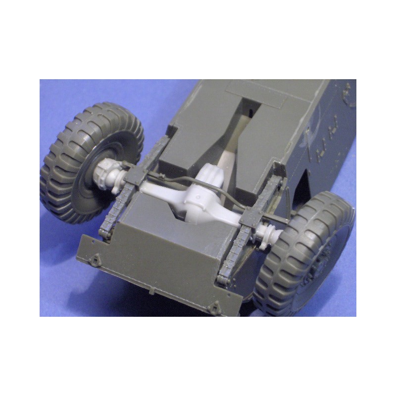
Parts D30 and D31 are the "ball and socket" to handle the turning of the front wheels. The open end of these parts connect with the wheel. The closed side, looks like half a ball with a cylindrical socket in the middle (visible on part D31 on the instruction sheet) connects to the front axle (B2 + B3 + D44).
The pipe/cylinder sticking out of the ball could be interpreted as the drive shaft.
Turning the wheels requires rotating the "ball" inside D30 & D31. This is obviously "impossible" (unless you scratch a new "socket" and find a suitable plastic ball) so the workaround would be to relocate the "drive axle" on the surface of the ball.
I would suggest that you remove the "drive axle" from the ball carefully so that it becomes a smooth ball, repair with small pieces of plasticard and file to shape if needed.
Insert a short section of rod or sprue to fill up parts of the hole inside D30/D31. Check with the inside of the front wheels (A57) to determine hoq much of the hole that is needed to get the wheel in place.
When the glue for the filling has dried it is time to drill a hole from the outside of the ball into the ball/socket. This hole is intended for the new "drive shaft". Insert a brass rod into the hole and glue it into the front axle.
Maybe, just maybe, it would be possible to reuse the axle ends after cutting them off from the "balls" but I wouldn't bet on it.
The difficult part will be to get both "balls" drilled at the same angle. Remember that the angle for the axle holes for the left and the right wheel must be measured from the front/rear or rear/front since one wheel is turned inwards and the other is turned outwards. One "ball" will have the hole at the front and the other at the rear.
Part D33 keeps the front wheels parallell so mount the socket on one side to the axle first, let dry, use D33 to check that the other socket gets the correct angle. The fit in the front axle can be adjusted a little by opening up the hole in the axle slightly. Don't know if the Staghound had toe-in, toe-out or the wheels absolutely parallell.
D22 and D23 seems to be the connecting arms to the steering gear so these need to be positioned to fit the steering angle of the wheels.
Don't overdo the steering angle, I don't know the maximum steering angle of the Staghound .....
/ Robin
Alternative method:

http://resicast.com/eshop/gb/accessories/159-staghound-steering-bronco.html

The pipe/cylinder sticking out of the ball could be interpreted as the drive shaft.
Turning the wheels requires rotating the "ball" inside D30 & D31. This is obviously "impossible" (unless you scratch a new "socket" and find a suitable plastic ball) so the workaround would be to relocate the "drive axle" on the surface of the ball.
I would suggest that you remove the "drive axle" from the ball carefully so that it becomes a smooth ball, repair with small pieces of plasticard and file to shape if needed.
Insert a short section of rod or sprue to fill up parts of the hole inside D30/D31. Check with the inside of the front wheels (A57) to determine hoq much of the hole that is needed to get the wheel in place.
When the glue for the filling has dried it is time to drill a hole from the outside of the ball into the ball/socket. This hole is intended for the new "drive shaft". Insert a brass rod into the hole and glue it into the front axle.
Maybe, just maybe, it would be possible to reuse the axle ends after cutting them off from the "balls" but I wouldn't bet on it.
The difficult part will be to get both "balls" drilled at the same angle. Remember that the angle for the axle holes for the left and the right wheel must be measured from the front/rear or rear/front since one wheel is turned inwards and the other is turned outwards. One "ball" will have the hole at the front and the other at the rear.
Part D33 keeps the front wheels parallell so mount the socket on one side to the axle first, let dry, use D33 to check that the other socket gets the correct angle. The fit in the front axle can be adjusted a little by opening up the hole in the axle slightly. Don't know if the Staghound had toe-in, toe-out or the wheels absolutely parallell.
D22 and D23 seems to be the connecting arms to the steering gear so these need to be positioned to fit the steering angle of the wheels.
Don't overdo the steering angle, I don't know the maximum steering angle of the Staghound .....
/ Robin
Alternative method:

http://resicast.com/eshop/gb/accessories/159-staghound-steering-bronco.html

 |


