

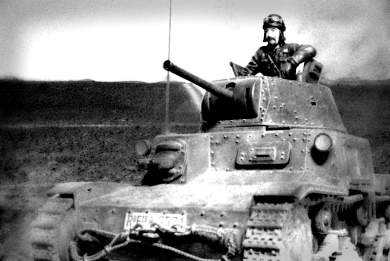
1⁄35M13/40 Ariete Division, Tripoli 01-1941
3
Comments
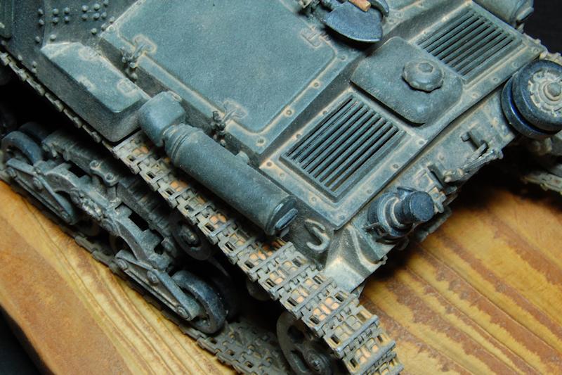
The mud scraper behind the sprocket didnt, I think, appear on the M13 until late 1941 so I removed it. This involved carving and sanding the moulded on mounting from the hull, as well as omitting the scraper component.
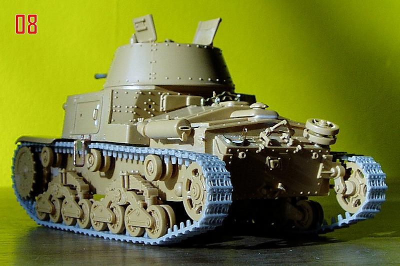
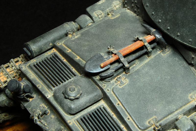
The mufflers in the kit have blank outlets which spoils their appearance, so these were opened out; it was quite tricky as the required hole is a very thin ellipse, too thin to get my files in. A line of holes was drilled then joined together using a new blade, the resulting rough slot being carved then sanded with thin strips of abrasive paper. I also sanded off the moulded on ridges around the body of the muffler as well as thinning down and sharpening up the little mounting strips moulded underneath which curl up under the outlet [photo 08].
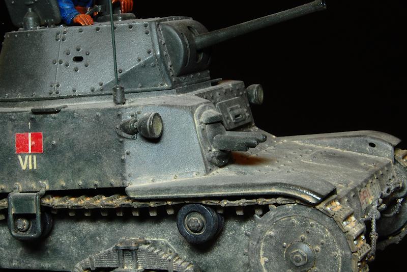
The handle on the side door was also replaced by a handmade item; a wire handle was threaded through two drilled holes and secured with CA from inside the door. The attachment point was two strips of plastic, top and bottom, with a Grandt Line rivet on each, which all blended in nicely once painted [photo 08].
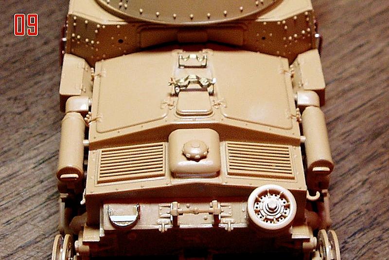
The kit tool brackets are a little chunky and rounded looking so I reproduced them from brass sheet. The hinge on one side is 0.5mm rod and the kit wing nut was used. The top part of the forward bracket was left off at this stage so that the tools could be inserted later [photo 09].
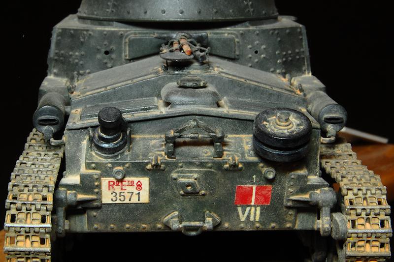
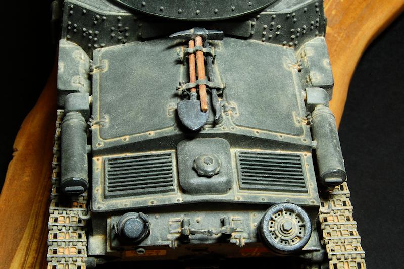
The radiator cover in the kit (with the filler cap on it) is of the late type, with overhanging edges; I dont think this is necessarily wrong in combination with short fenders, but as it turned out, the actual vehicle which I decided to use for the colour scheme had the early type cover. This is when I could have modified the cover, probably by laminating, carving and sanding plastic card. The shape is quite simple and the In Action book has drawings of the differences in shape of the two types. Instead I inserted a single layer of plastic card underneath the cover to raise it a little as the gap up to the top of the engine covers looked a bit too big. Another omission is two bolts or rivets at the rear of this cover. Anyway, the lesson here is to decide on your colour scheme and the exact variant youre building before going too far with the build (something which I usually fail to do.)
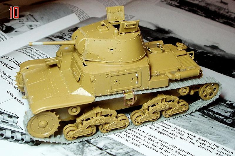
As I said, the construction of the kit is quite quick and easy, with only one or two small defects. A little filler was applied to the top of the machine gun cowl where a small depression had formed, and also I needed to do a bit of dissolved sprue filling where the body meets the hull at the nose. The gun seemed a bit too tapered so some filler near the muzzle thickened it up a bit photo 10]. It is a pity that the two brake access hatches on the front arent moulded as separate parts, or at least given a bit more definition, and the same could be said of the storage boxes; I tried to improve the definition of the box lids by sanding the side to create a lip, but remaking them might have been better and not too difficult.
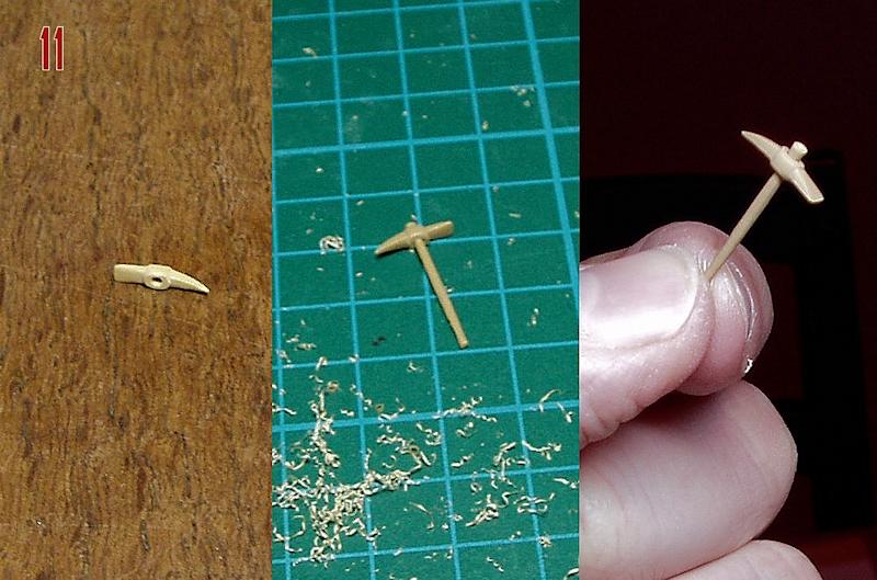
One of the kit tools is a sledge hammer, but since most photographs show a pick axe instead, I made one. The basic shape was drawn on to a piece of the kit sprue, and the hole for the handle drilled for reference in order to keep the profile right. Most of the plastic was carved away with a blade, the rest removed by filing. A handle carved from another piece of sprue fitted into the head, just like the real thing [photo 11].
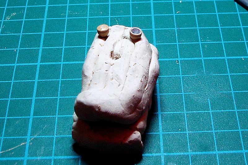
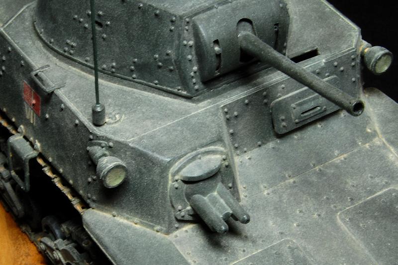
The headlamps were hollowed out just scraped out by hand rotating a knife blade, with the part held in a lump of cold Plasticine then painted inside with silver prior to filling with Araldite epoxy. This is the first time Ive done this, and a lesson learnt was that I think it is best to also paint the outside rim of the lamp face prior to adding the epoxy; doing the epoxy first meant painting a circular rim around the lens by hand which was more difficult. The armoured twin machine guns and the coaxial one were also drilled out.
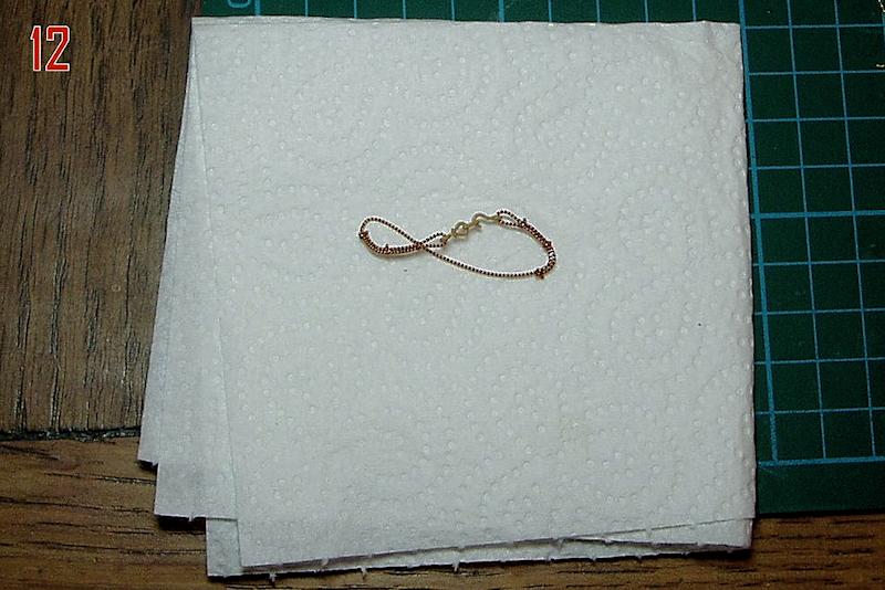
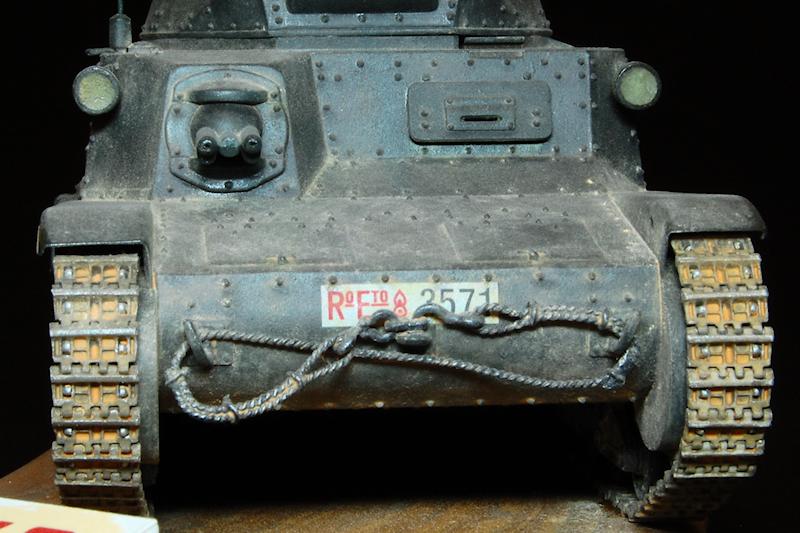
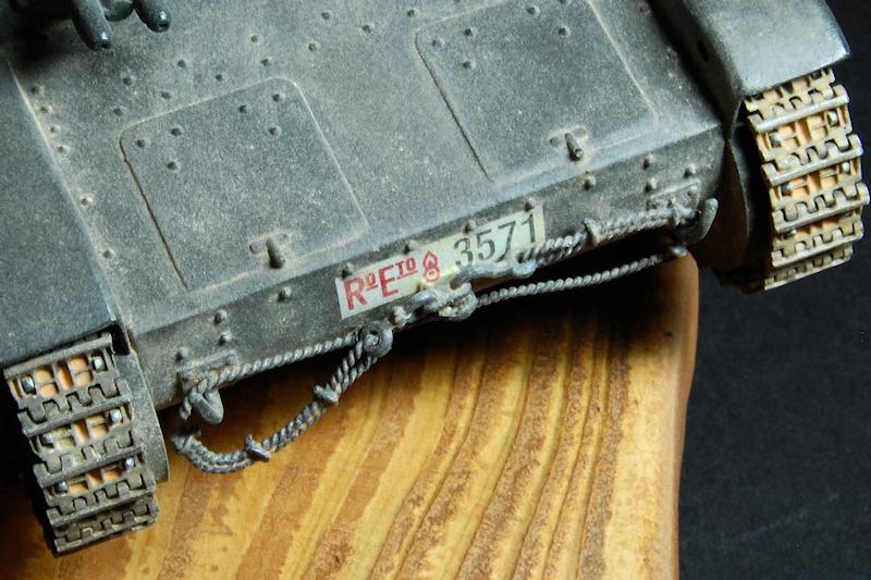
The tow rope provided is one moulded piece. The cable part was quite easily cut away, leaving just the hook and shackle, which was then drilled to receive a new cable. The new cable was two strands of copper wire: these were clamped into the pin chuck at one end, and with a pair of pliers firmly holding the other end, the chuck was rotated until an evenly wound rope was made. Rather than the rope loops being secured by a single collar as per German tow ropes, these had a long loop of the cable folded back then anchored at three points by small clamps about 30cm apart. These were represented with small wire loops CA glued into place at the same time that the rope was being coiled into the right shape to fit the hooks on the front of the hull; it was then attached to the drilled out hook and shackle [photo 12].
The last detail added, after all the painting was done, was the aerial, made from 0.5mm styrene rod slightly sanded to a taper at the tip. Working from photos I think a scale aerial should be 50mm (1750mm full size) which is considerably longer than that provided in the kit. However, I think my early 1941 version possibly shouldnt have an aerial at all since radios werent fitted to all these tanks at this time. To delete the aerial you would need to remove all the mounting detail so that the top of the deck is completely plain, matching the other side. Incidentally, photos can be misleading on this point since the aerials folded down, so may be totally hidden when viewing from the opposite side making it unclear whether the vehicle has a radio or not.
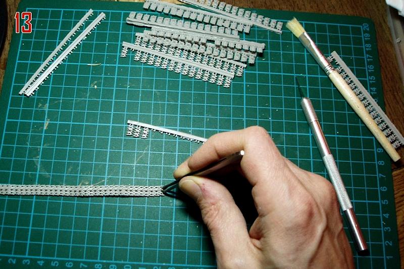
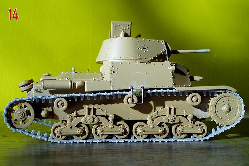
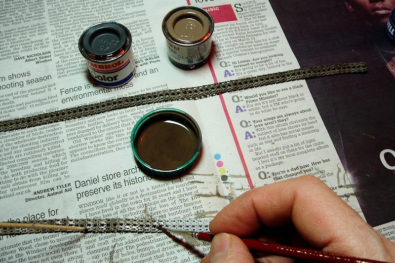
I was a bit worried when I opened up the Model Victoria resin track links, as I imagined having to carefully clean up all of the considerable flash, but in fact it was mostly easily removed by scrubbing with a hog bristle paint brush, much of it while still on the sprue. Once the part was removed, a further clean up was done with the bristle brush, and the ends of each link tidied up with a sharp blade. Assembly is much quicker than with the metal link and pin type; tweezers with flat angled ends were perfect for pushing each successive link into place with a click [photo 13]. There was the odd broken or slightly malformed link, but enough spares are provided as back up. These tracks are slightly more delicate than the metal type, but the linkage is strong enough so that when I tried them out for fit before painting, the sprockets engaged accurately and the tank could be rolled along on them just like the real thing [photo 14]. It occurred to me after construction that it might be possible to take advantage of the track tensioning device on the idler wheel in order to get the tracks to fit more tightly; the idler could perhaps be cemented in place at the time the tracks are fitted rather than beforehand. Photos of the real thing usually seem to show the tracks being quite tight with only a very small amount of sag. I think on one side of mine there is too much sag.
About the Author

FROM: ENGLAND - SOUTH EAST, UNITED KINGDOM
Earliest model memory is a Super Sabre my grandmother bought for me around 1972. Have always dabbled in painting and making things, and rediscovered doing that with plastic in 2008. Vowed then to complete the 30 year old stash, and have made some progress. Hobby goes hand in hand with BBC Radio 3...
Comments

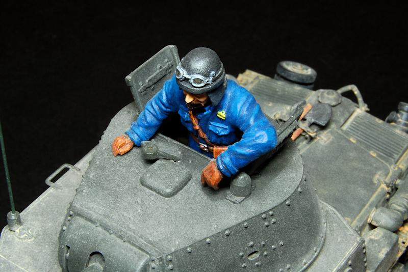
Very enjoyable read Matthew, and nice job on the diminutive M13/40. The AM tracks were well worth it, IMO. Bannerman's book must be very good, or you're a natural figure painter, as your commander came out extremely well...and both eyes look perfect to me! Thanks for sharing this one.
OCT 09, 2012 - 09:14 AM

Matthew,
Your M13/40 is well built and looks like it's put dozens of dust miles under its tracks. Well done!
I concur with James, your commander looks very convincing.
OCT 10, 2012 - 03:11 PM

Hello, I am writing from Italy and I like the WWII African war. The "M13/40 II serie" you have build is o good subject, but a first sight you have made two errors: the front plate because the second serie has not and the number of plate because the VII battalion had number between 3002- 3030 approximately. Finally the "cupolotto" on the radiator, smooth and without the upper fins for cooling as you can say from your photo for inspiration. Write to me for other request if you want...
SEP 16, 2016 - 12:47 AM
Copyright ©2021 by Matthew Lenton. Images and/or videos also by copyright holder unless otherwise noted. The views and opinions expressed herein are solely the views and opinions of the authors and/or contributors to this Web site and do not necessarily represent the views and/or opinions of Armorama, KitMaker Network, or Silver Star Enterrpises. All rights reserved. Originally published on: 2012-10-08 00:00:00. Unique Reads: 17349

WEB HOSTING BY


Copyright ©2021 Armorama and Kitmaker Network, a subsidiary of Silver Star Enterprises
All Rights Reserved. Please read our Conditions of Use and Privacy Policy.
All Rights Reserved. Please read our Conditions of Use and Privacy Policy.