

1⁄35Czech ARRV VT-72B
Introduction
The VT-72B is an armoured recovery and repair vehicle based on a T-72 chassis developed by the Czech republic. It was in service with the GDR army under the denomination T-72TK.
It is fitted with numerous accessories including an orientable crane with a 19tons maximum capacity, a front winch, a winch set in the rear platform and a little winch located behind the TC station. It's armament is a 12.7mm NSVT AAMG.

The kit
The kit is produced by Panzershop. It comprises 377 resin parts and 290 PE ones, Friul tracks and a Modelpoint antenna base. The instructions are on a CD-ROM full of real vehicle pics and in progress kit ones. Despite this they remain quite hard to follow because no locating marks are present on the parts. We must frequently check on the real vehicle pics the correct location of the parts. Frequent dry-fitting is necessary before gluing with cyanolite.Due to the very large number of parts, some do not appear on the various pictures. Some minor reference errors are present but a thorough study of the parts should avoid mistakes
The interior
It comes as a "tub" in which the various parts are glued. The parts location does not create any trouble. The fire extinguishers on the rear wall are ill located. They must be glued higher than where Panzershop shows thus we are obliged to shorten the bottles.The seats are tricky to build all the more because the instructions lack precision. Again, the real vehicle pics are needed to get an accurate result.
The many PE parts give some finesse. Some are hard to handle such as the extinguisher straps or the rack behind the dashboard which is too long and needs to be shortened to allow the shaping. Panzershop has engraved the fold lines to ease the bending. Some being on the wrong face, they require attention to avoid breaking the parts. Prior to enclose the compartment we need to check the good alignment of the parts to prevent any blocking. Then the interior is painted according to the instructions and the CD-ROM pics. Do not forget to apply the decals.


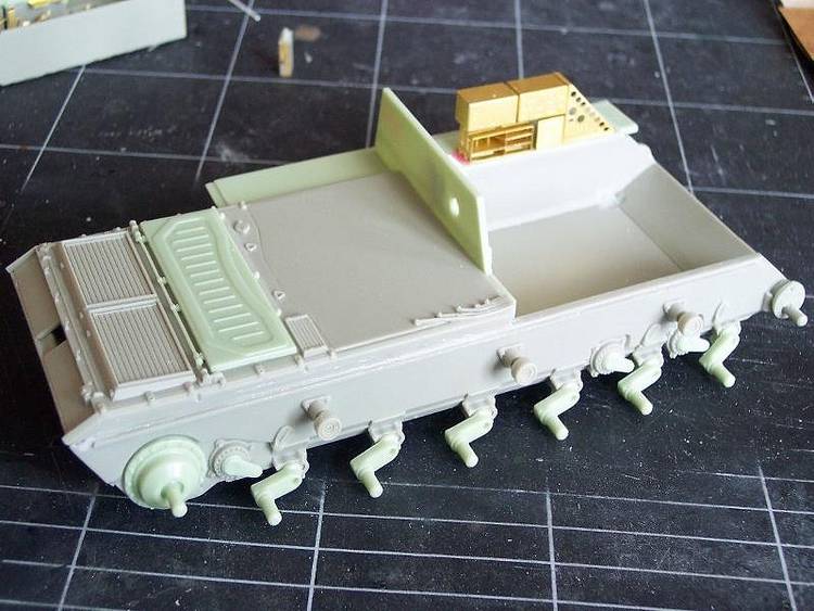
The chassis
The hull is a straight copy of Tamiya T-72 whose front part has been slightly modified. Despite the lack of instructions, it builds easily thanks to the excellent fit of the parts coming from Tamiya. To facilitate the painting, the wheels and sprockets are set apart. Then begins a long series of blank tries to avoid any bad surprises.The various bins and their PE locking devices are installed. Those located behind the driver compartment rest on PE supports which need to be cut to have them horizontally set.
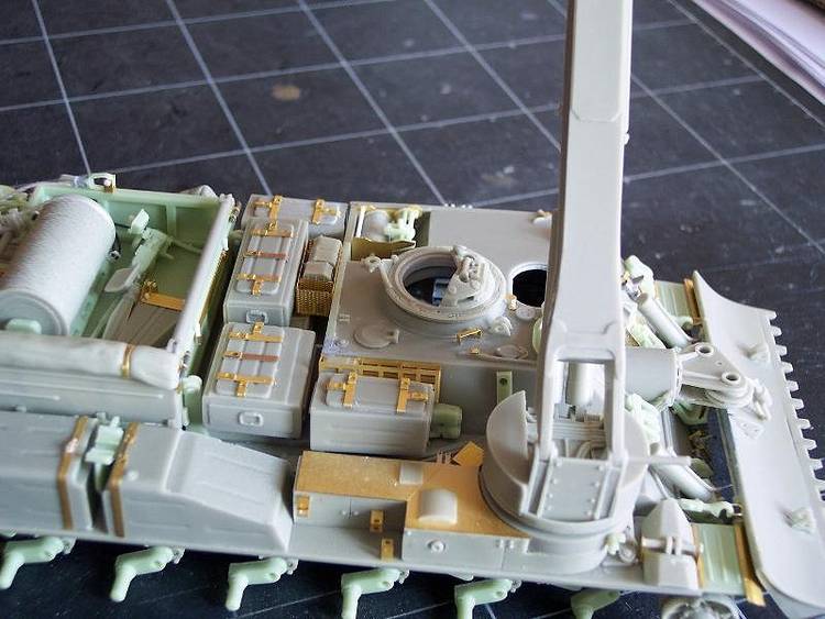
The moveable stowage platform on the rear deck is built separately. It has jacks which are drilled out to ease the installation. The foldable walls are set closed and their locking devices re-done as those in the kit are oversized. The large winch is detailed with its hydraulic conduits. The tubing under the platform should be dry-fitted because they jut out the platform and could prevent a good final assembly.
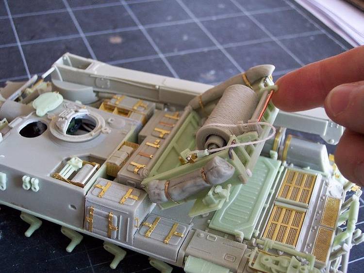
The crane is issued with two arm extensions to represent the boom in the stowed or working position. The arm build is easy. The jacks are detailed with the hydraulic conduits with the help of the real vehicle pics. They are made of heat-shaped plastic rods . The jacks are drilled out and remain moveable. The drum for the cable is installed as well as a small roller which supports the cable while it is unwound.
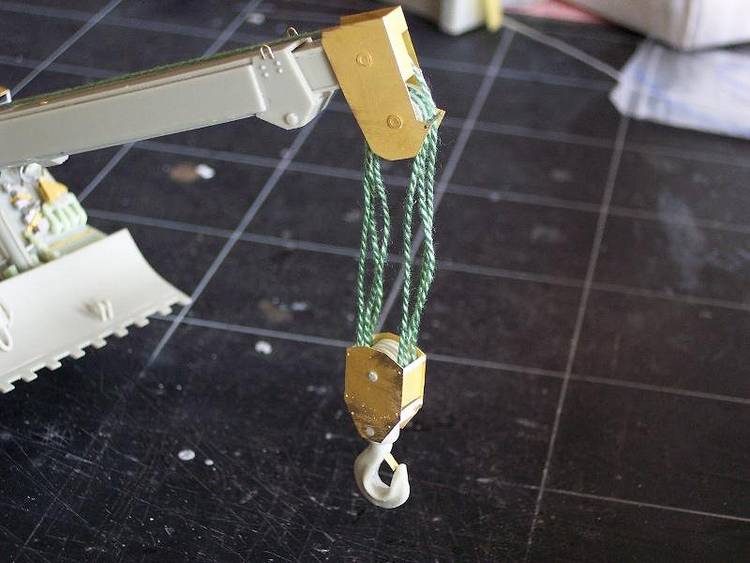
The setting of the hoist is much more uneasy. We must first build the part attached to the arm and pass the cable through before winding this one around the three pulleys of the hoist. Then the cable end is secure under the boom. When the cable is in place, it need to be tightened and wetted with white glue to give it some stiffness.
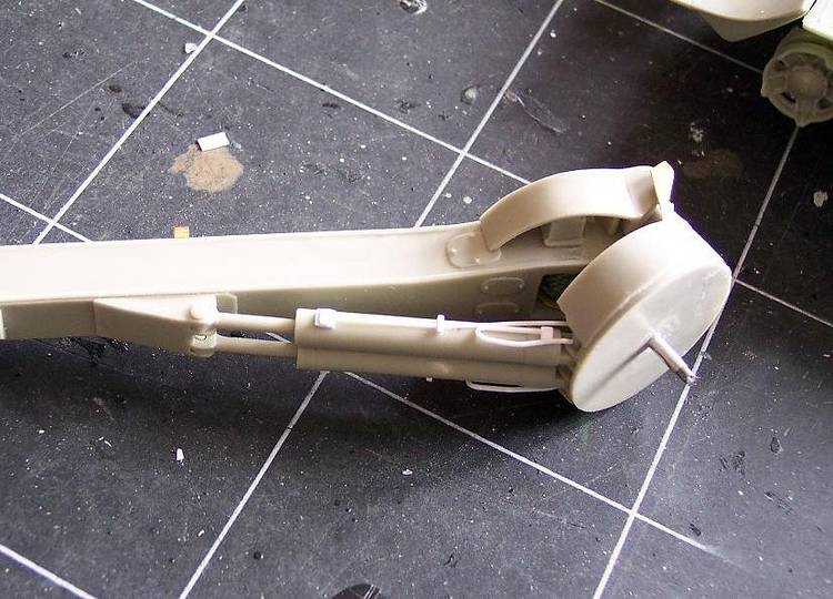
The front blade requires a lot of attention. In fact, there are no markings to glue the arms to the blade so a bad alignment could occur which would be noticeable only when assembled to the jacks on the ARRV glacis. In such a case, we need to start from the beginning again. Once again, dry-fitting is needed. Two little eyelets are added, they help keeping the blade in the raised position when attached to hooks. The latter are detailed with a lever which help screwing the hooks. The jacks should remain moveable to facilitate the installation of the blade. The right one is hampered by a part located at the crane base which needs to be thinned to enable the fitting of the jack.
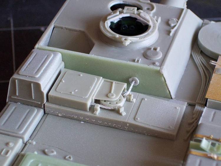
The building ends with the tools and various accessories. Several tools were broken in the box so they have been redone from plastic card and rod. The flashing lights supports are set in place, but the lights will await the painting of the vehicle. The power cords are represented.
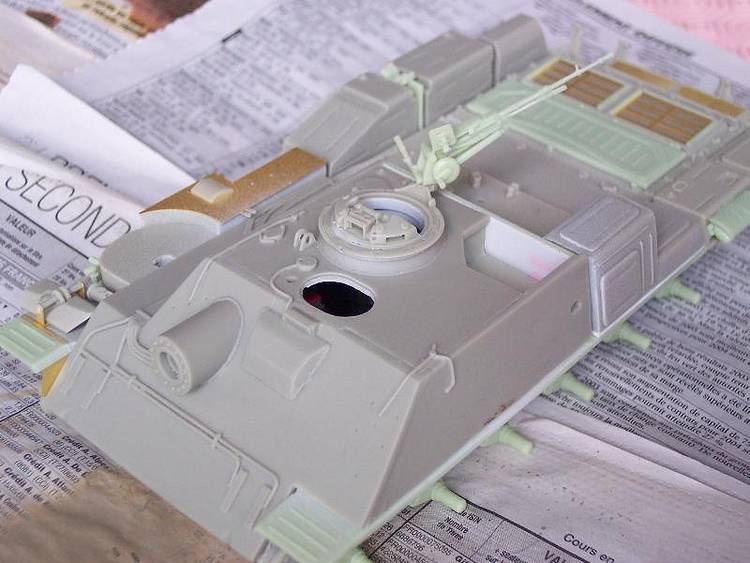
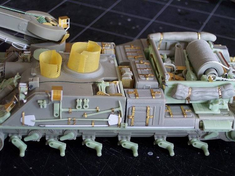
The weapon station is detailed with some handles and levers. The TC windshield is laid down in the transport position on the left side of the rear platform. The small winch on the roof gets its cover. Its securing rods are detailed. The cable is attached and threads through the rollers of the part R173 which is also detailed according to the pictures.
Several parts are not installed. The jerry cans and their supports are left off as they are not present on any picture available.
The tool to prevent the blade driving into the soil is not installed but stowed on the platform. The chainsaw is stowed there too.
Prior to fitting the wheels and the tracks, the chassis is painted and partially weathered


About the Author


FROM: CORREZE, FRANCE
I have been in the hobby for years and I'm still learning. As a modeler, I only build 1/35 modern military vehicles, mainly armored ones. I also run a website where I share a lot of walkarounds. Just click on my banner to pay a visit to it.
Copyright ©2021 by Olivier Carneau. Images and/or videos also by copyright holder unless otherwise noted. The views and opinions expressed herein are solely the views and opinions of the authors and/or contributors to this Web site and do not necessarily represent the views and/or opinions of Armorama, KitMaker Network, or Silver Star Enterrpises. All rights reserved. Originally published on: 2005-05-20 00:00:00. Unique Reads: 20356

WEB HOSTING BY


Copyright ©2021 Armorama and Kitmaker Network, a subsidiary of Silver Star Enterprises
All Rights Reserved. Please read our Conditions of Use and Privacy Policy.
All Rights Reserved. Please read our Conditions of Use and Privacy Policy.