1⁄35M1A1 TUSK Build
9
Comments
Thanks to Darren(CMOT) and Jim for the opportunity to build another review model for the web site.
Introduction
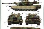
We have in the making the Rye Field Models M1A1 TUSK - M1A2 SEP TUSK I/II 3 in 1 kit. First impressions when I opened up the box was "WOW!" Looking at all the parts kind of reminds me of a Dragon AIM kit combined with a Tamiya M1A2 TUSK kit. At first quick glimpse, there was no flash evident. The usual mold lines could be seen, but very faint. Another quick glance at all the parts reveals that not only can the M1A1 TUSK be built, but a plain M1A1 be built by providing the regular side skirts along with the TUSK side skirts. Surprisingly, 3 different types of APU's are provided, the one under the rear deck, the one seen in the bustle rack, and the one that hangs off the right rear as seen on M1A1's during Desert Storm. A "HOFFMAN" device is also included. More, if any, extra's in the kit will be noted as I progress through the instructions.The Build
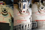
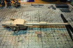
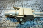
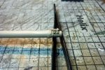
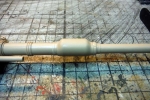
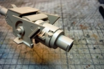
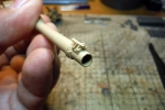
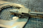
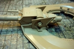
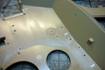
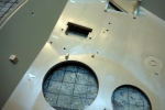
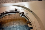
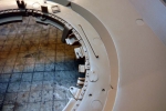
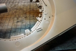
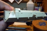
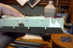
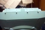
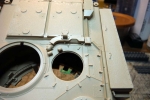
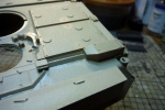
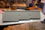
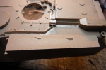
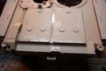
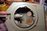
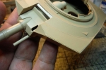
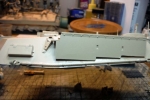
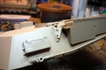
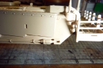
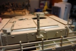
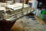
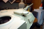
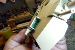
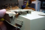
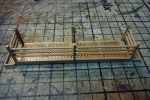
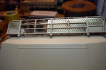
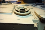
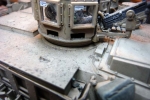
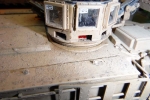
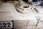
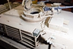
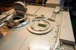
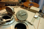
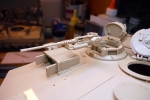
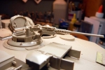
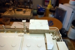
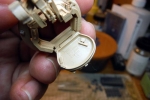
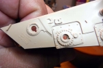
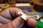
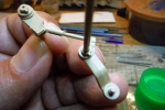
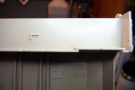
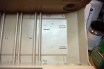
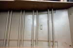
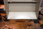
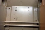
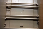
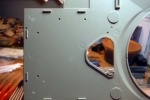
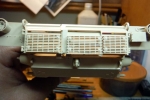
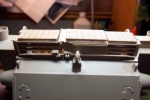
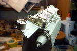
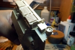
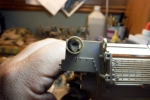
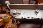
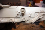
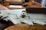
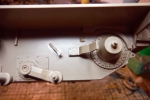
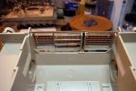
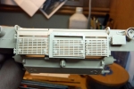
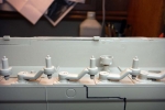
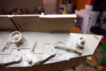
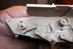
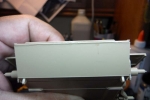
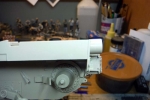
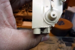
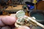
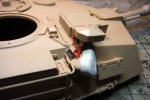
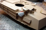
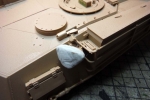
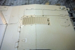
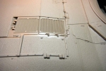
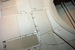
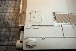
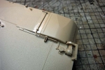
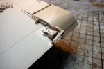
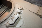
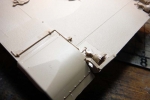
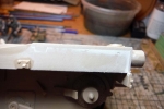
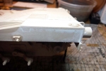
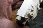
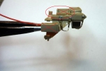
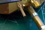
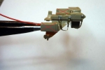
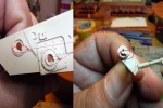
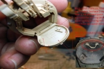
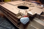
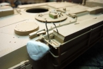
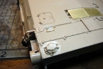
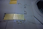
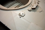
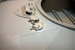
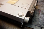
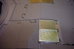
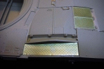
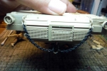
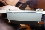
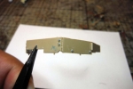
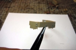
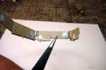
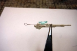
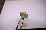
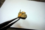
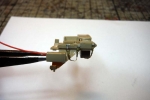
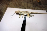
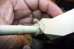
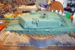
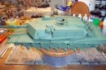
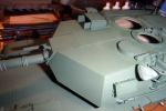
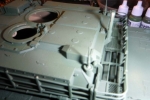
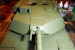
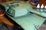
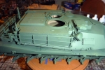
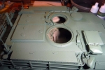
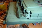
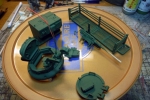
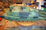
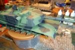
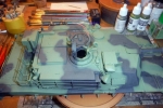
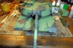
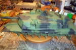
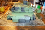
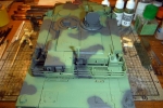
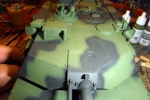
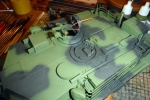
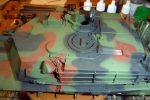
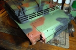
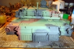
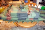
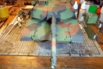
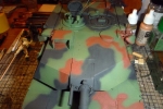
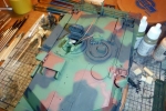
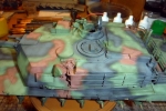
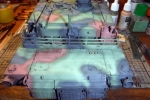
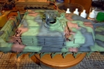
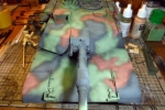
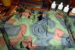
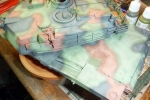
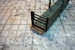
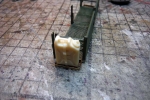
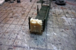
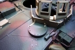
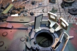
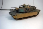
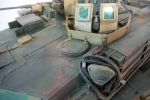
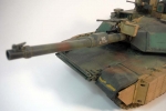
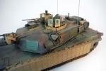
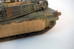
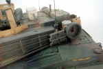
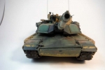
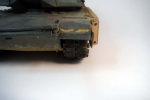
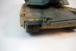
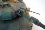
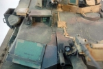
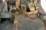
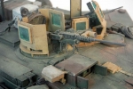
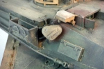
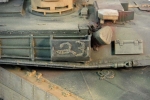
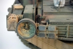
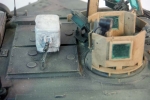
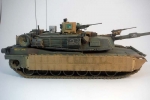
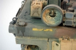
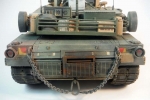
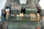
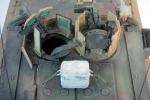
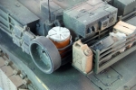
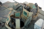
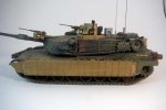
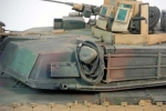
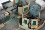
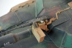
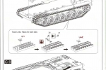
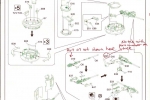
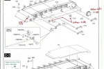
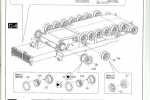
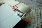
First step was to choose what vehicle I was going to build. There are three vehicles that can be built out of the kit, a M1A1 TUSK, M1A2 SEP TUSK I, and a M1A2 SEP TUSK II. I chose the M1A1 TUSK painted in NATO 3 tone camouflage with tan TUSK parts. I like how the tan parts look against the NATO camouflage. While looking over the marking guide and doing some research on vehicles of 1st Battalion, 35th Armor Regiment, I noticed that either the kit decal bumper number or bore evacuator name is incorrect. Thanks to Gino (Heavy Arty) and his pictures of the real thing, I found out that the real bumper number for "Bad Blessing" should be "B23." Other than picture reference, the way you can tell that either the bumper number or the barrel name is incorrect, that the first letter in the barrel name is the same as the letter in the bumper number. Therefore, since the barrel name is "Bad Blessing" therefore the bumper number should be "B-??." First step in the instructions is not a number step but a letter step, "STEP A." This is the barrel for all 3 variants. Little cleanup was needed on the parts. Just the faint seem line along the barrel pieces needed some light sanding. The fit on all the pieces was spot on and no filling was needed. The breech is not complete. This is one of the many hints that an interior will be included in another production and the rest of the breech will be included. Fit of the completed barrel assembly to the lower upper hull was nice. There was no problem placing the barrel in its spot, nor did it snag against the bottom upper hull and moved freely. I provided the real measurements of the real thing for the Dragon AIM kit/ So I used the same measurements and compared them to this kit and so far it is spot on. I wanted to put a couple of the tracks together to see how they went together. I did find the first correction to the instructions. The track pads are numbered backwards. When I assembled the tracks, although there are very nice, I found that some of the pads came apart while handling and painting. For those pads that came apart, I just dabbed a small amount of Tamiya Liquid Cement in the locating holes. I’ve provided a comparison of the A2 cupola/TC station between RFM, Tamiya, and Dragons since there has been talk about the RFM kit cupola has the wrong dimensions. As you can see, the RFM kit is way off in the area of the TC cupola meeting the hull. In my opinion, I think the Dragon SEP kit is spot on. I'm glad I went with building the A1 TUSK instead of the A2 SEP w/TUSK. In the instructions, the M1A1 with TUSK is highlighted in green and the A2 with TUSK is in black. After dry fitting the barrel, I proceeded to step B-1 and drilled out all the holes were the TUSK components will be mounted. After that, I jumped to step B-4 and glued the two halves of the turret together. Using liquid cement, little to no putty will be needed. A light sanding of the beaded up plastic will clean the bottom of the hull up. The rear panel was a good fit and again, little to no putty was needed. Steps B-2, B-3, and B-5 are adding turret details like the side storage boxes, gunners sight, blow off panels and TUSK parts. *NOTE* USE BLOW OFF PANELS PART B30 AND 31 ALONG WITH 6 X C16. The TUSK parts will be added later for two reasons. Reason one is for ease of painting since the TUSK parts will be in tan and the vehicle will be NATO 3 color. The other reason is because the whole “J” sprue was missing from the box and RFM and Jim got that taken care of and it’s on the way to me. For plastic, the tow cables look pretty good. The cables were already shaped and all the mounting holes helped keep them in place. The FBCB2 transceiver, GPS and smoke dischargers were all cabled up. Two types of wind sensors are provided in the kit. Check your reference to see what sensor is on the vehicle your building. First, I want to apologize for giving out wrong information. I was asked if the road wheel arms were movable in this kit and I answered yes. The way the kit is built, the road wheel arms are not meant to move. Torsion bars are included, but the arms have locking pins. It is possible to have the road wheel arms move by removing the locking pin. Next is more evidence that there could be a full interior, including engine, coming from RFM soon. This picture shows a location point where the batteries would go. The only thing is that on the hull, the doors to access the batteries are molded to the hull. Maybe a new hull will be included? There was a major problem with the TC hatch. See photo provided. The engine doors and grills look very good. They were a bit tricky to put together but if you attach the hinge parts first, then attach the doors, it goes to better easier. The tail lights are not that bad looking either. Road wheel arms, torsion bars, return wheels and all the other nick knacks that go behind the tracks went on with now problem. Even with the locking pins, there is still a little play with the road wheel arms, so use a straight edge or something level to level out the arms while they dry. Now was the time to mate the upper with the lower hull. The front of the hull was a good tight fit. Under the left and right rear has some small gaps. If it bothers you, you can fill these gaps, but for me, since you will not see them, I will not bother filling them. There are 3 places on the hull that will need to be filled and sanded and fixed. First is the front glacis plate. The front did have the weld seem molded on the bottom hull, but it was faint. So I sanded it all down and will use some Evergreen rod to replace the weld bead. Next spot that will need filler and sanding is the right rear side of the hull. Since I am building the M1A1 with Tusk version, I used the fuel cell panel that goes glued atop the right rear. The “u” shape and lip seen on A2’s with the APU and or Hawker Batteries is not visible on the A1 that I am building, so fill and sand this area. The other area is where the upper hull meets the rear. This needs to be filled and sanded. Next, we will tackle the issue of the grab handles on the rear deck. Most of the natural panel lines of the deck cut through the handles. One handle that is located on the panel above the battery compartment is missing the handle entirely. This is where your spares box comes in handy. I have kept all the leftovers from the Abrams photo etch frets I’ve built over the years and had plenty of handles left over. Next we added the retaining chains for the fuel caps and the photo etch grills. The fenders and headlights were next. Two types of fenders are provided, so check your reference to see which ones to use. The bars that hold down the fenders are plastic in the RFM kit. They are very fragile, so care is needed when cleaning them up. I prefer the metal ones that Dragon provided in their kit. Again, care is needed when slipping the track connector on to the bar if you use the plastic ones. Now I moved my attention to the .50 Cal and 7.62mm. The .50 needed some chains which held the retaining pins to the cradle. Also, make note, do not attach the charging handle to the gun. Instead, scratch build a pull handle out of wire and plastic rod and attach it where the charging handle goes. Safety chains are also needed to the cradle for the .50 that mounts to the barrel. Also, the power cable for the search light was added after the big hole in the rear of the light was filled. The 7.62 needed two chains for its retaining pins and a small pull ring for the cradle locking pin. A charging pull handle made from fine wire is also added. Last was adding missing nuts and bolts and replacing molded on bolt heads with more well defined ones from MENG Models for the TUSK parts. The main colors of the NATO camouflage were done with Tamiya 3 NATO colors. Details where picked out with Vallejo paints. The tracks were painted with Tamiya Metallic Gray and NATO Black and heavily dusted with MIG Pigments. Pin washed, oil filters, dry brushing, and MIG Pigments finished out the rest of the weathering.Conclusion
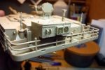
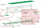
All though a nice M1A1 can be produced from the kit, there are some minor errors that have been found in order to depict "Bad Blessing" correctly: 1. Incorrect bumper number. "Bad Blessing" should be B23 and not A23. In the actual photograph, the bumper numbers are covered in 100mph tape, so easy fix is cover decal with Tamiya tape. The following two errors/corrections were caught by Jacek(Jacek_Placek): 2. No track end connectors are present on the real vehicle hanging off the fender retainer bars. 3. The position of the search light on the barrel of the 50. Cal is in the wrong position and the wire conduit and deflector are on the wrong side. *NOTE* While looking at the photo's I did have of "Bad Blessing," there is something that looks like a box in the bustle rack next to the APU. I made an educated guess and came up that the box is the BII box from a 5ton truck or something like that. So what I did was snag the BII box from one of Italeri's 5ton truck kits and cut of the mounting brackets and slid it in the rack. I hope you enjoy my build and I highly recommend this kit to any modeler, whether beginner or experienced. The beginner can build a nice model straight out of the box and the experience can fix all the minor issues. Please refer to my build blog for any other questions and as always, any comments and or critiques are always welcomed.Comments
Great job on "Bad Blessing". It was an interesting tank abd your rendition of t looks great. Great how-to as well.
WTF - rivality
JUL 26, 2016 - 03:56 AM
Pete...VERY nice build man, and like HA said, great how to stuff...!
JUL 26, 2016 - 05:46 AM
Great work Pete, and the review is excellent. while the kit sounds great you convinced me that the Dragon AIM and Sep in my stash are still good.
AUG 15, 2016 - 06:30 AM
Copyright ©2021 by Pete Becerra. Images and/or videos also by copyright holder unless otherwise noted. The views and opinions expressed herein are solely the views and opinions of the authors and/or contributors to this Web site and do not necessarily represent the views and/or opinions of Armorama, KitMaker Network, or Silver Star Enterrpises. All rights reserved. Originally published on: 2016-07-26 09:44:54. Unique Reads: 24759


