This is the blog about Trumpeters sFH18 that I reviewed a while ago you can see the review on the following link Trumpeter 15cm sFH18 review
So I started building it last weekend and basically here is a chronological step by step blog of how it builts up. Again I need to give some credit for trumpeters instruction booklet. Where every step usually combines 2 or 3 steps in which you make subassemblies and usually the same step also shows where the subassembly needs to go. However still I managed to misread it a couple of times so far. You will read a bout it later.
Starting with
step 1
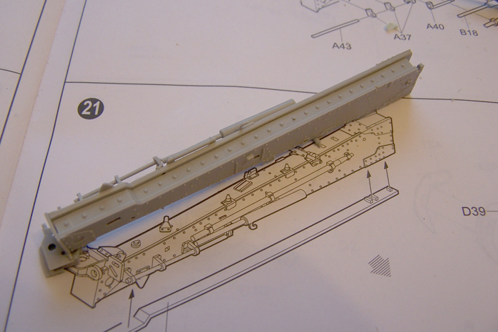
Where the base of the carriage is started. 2 steps. Starting with the top and the bottom being attached to each other. A little note here. On the insides of the parts B1 and B2 you will find ejectorpinmarks.; You can fill them but it is not neccesary because they are on the inside and will be hidden by the parts that are attached later on. And further a small moldline needs to be romoved from the sides.


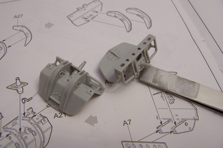
The second step in step 1 Shows the sides and the back being added to the base of the carrage. The sides are made up with 3 parts this means that you have to fill and sand the gaps where the parts meet up. This is at the round ends of the carriage. See second pic


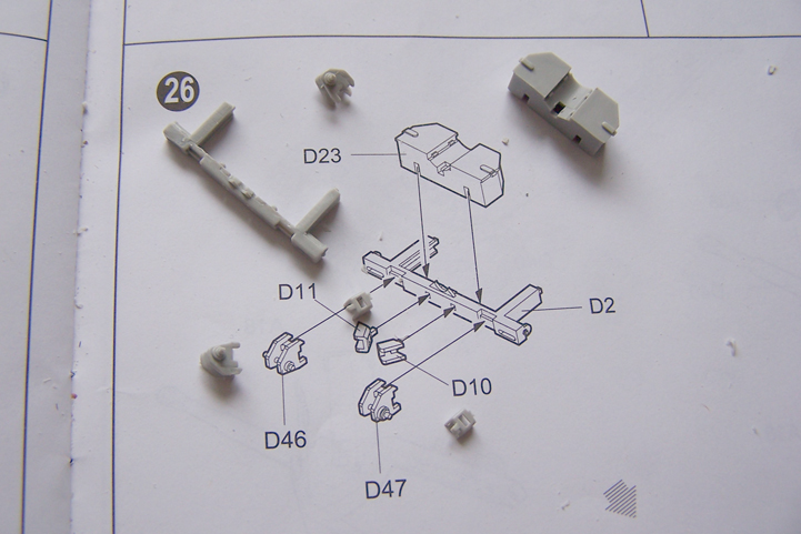
Step 2
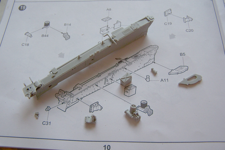
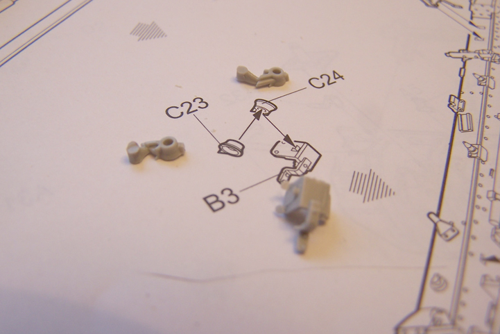
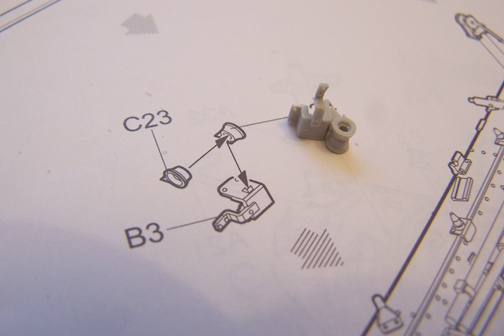
shows actually 3 actions. Again a subassembly for a part that needs to go on the carriage. A picture of two parts being added to the back of the carriage and a drawing of how the subassembly you just made attaches to the underside of the carriage. (can you still follow me)

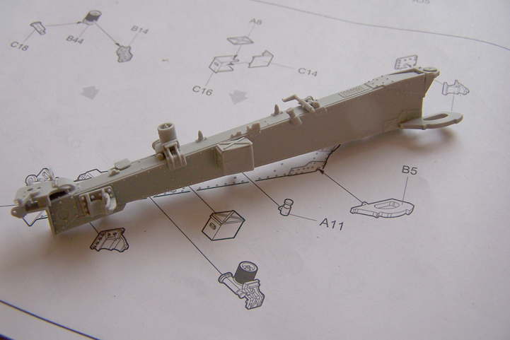
Starting off with the parts that need to go on the back of the carriage

And how it looks attached.

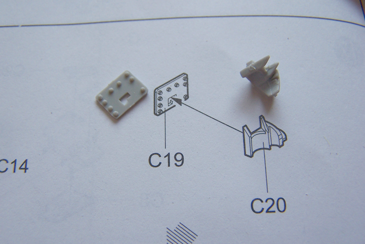
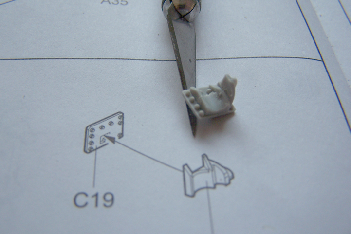
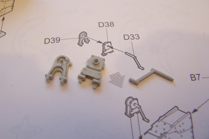
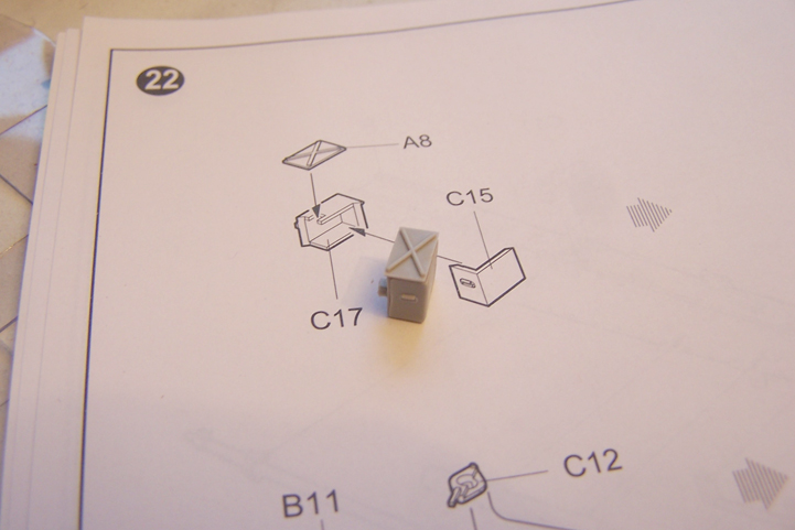
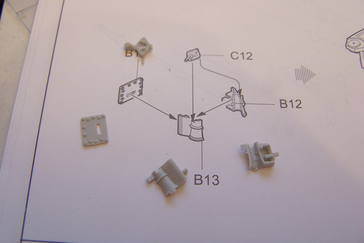
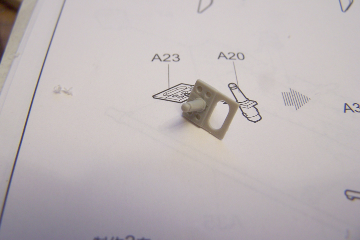
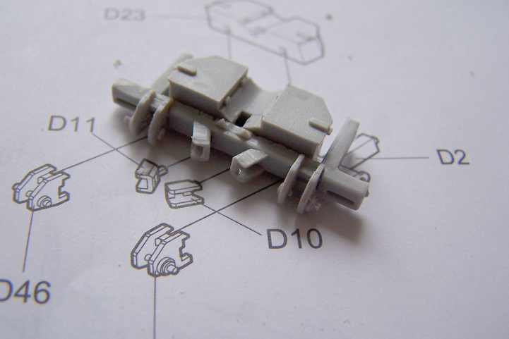
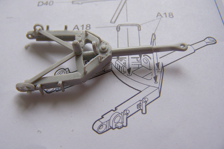
Then on to the subassembly of a thing with 2 levers. which need to go to the underside of the carriage.

And here Trumpeter did something odd. The levers have both a round pin but the holes they need to go in are Square. You either have to adjust the pin or the hole. I adjusted the hole by scraping round it with an Xacto

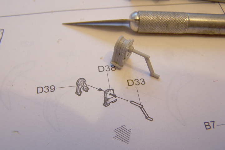
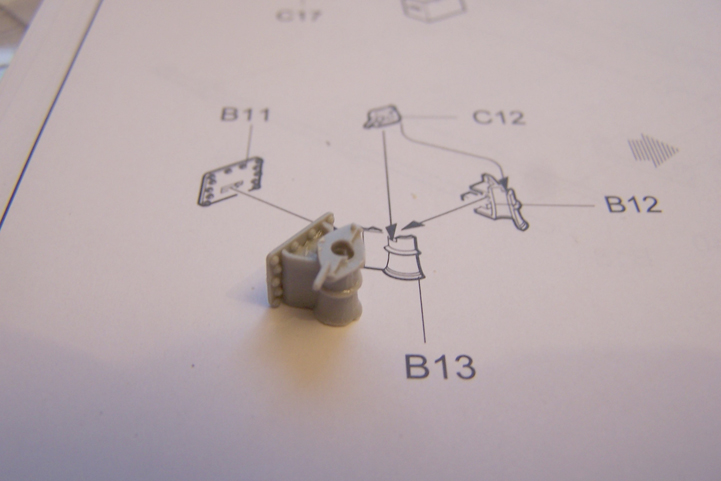
And this is how it looks assembled. (actually when I was working on these pics this afternoon I found out I had misread the instructions and the levers should be the other way around. Have fixed that by now)

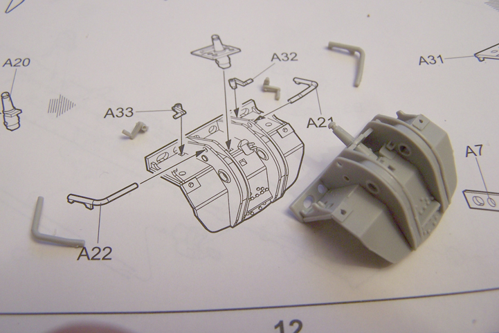
Next step is adding the thing with levers to the carriage bottom


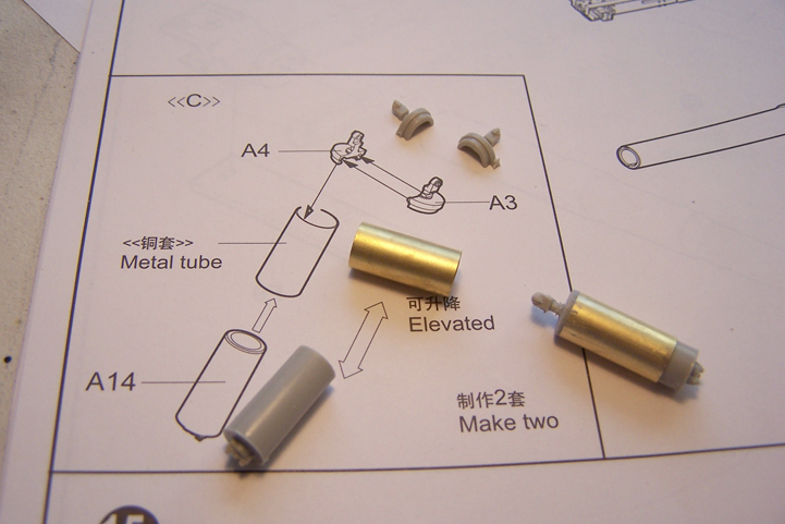
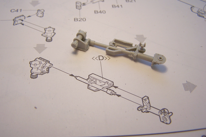
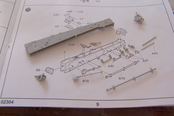
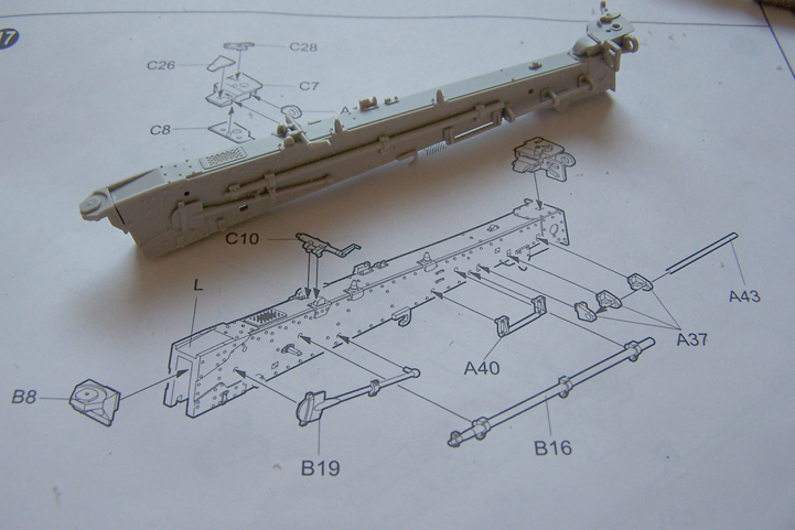
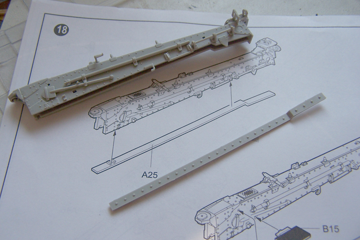
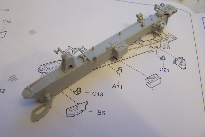
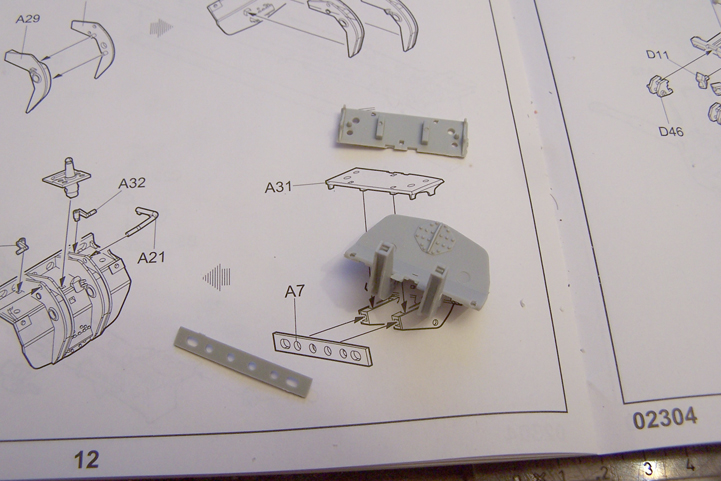
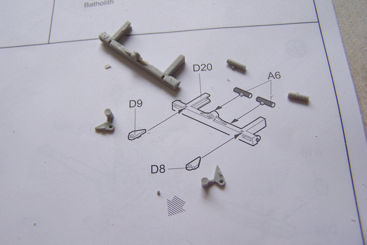
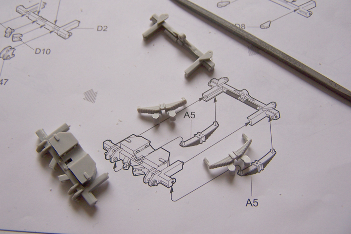
Step 3
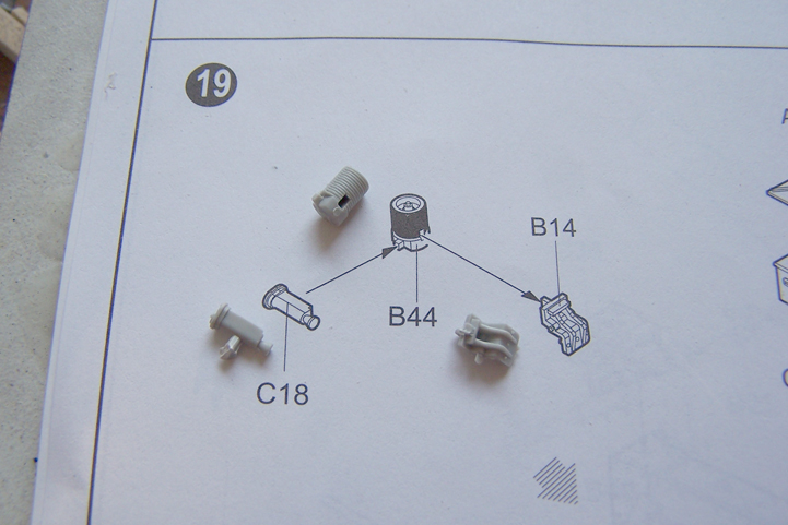
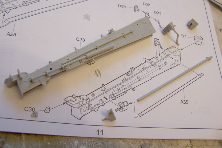
again consists of 3 Actions. The Axle with the leafspring. Some kind of mechanism with two adjustment wheels on both sides that needs to go to the front of the carriage and step 3 shows how all the subassemblies are added to the carriage. On the axle you need to remove some pretty big mold lines on both sides and some ejectorpinmarks need to be filled on the leafspring. I did this with CA glue and some sanding with the Fibreglass pen.
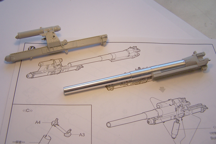
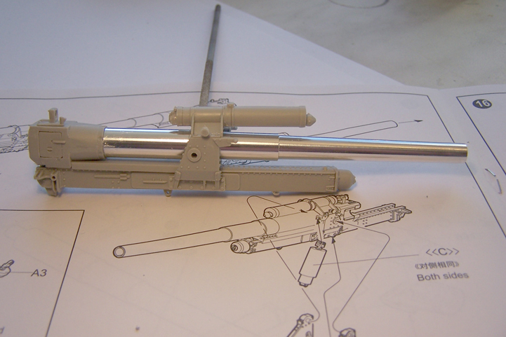
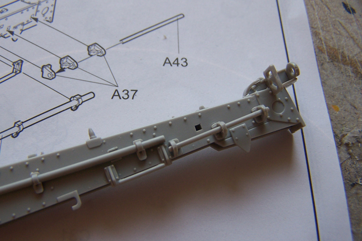
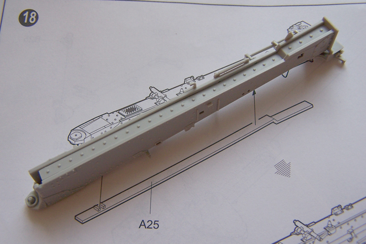
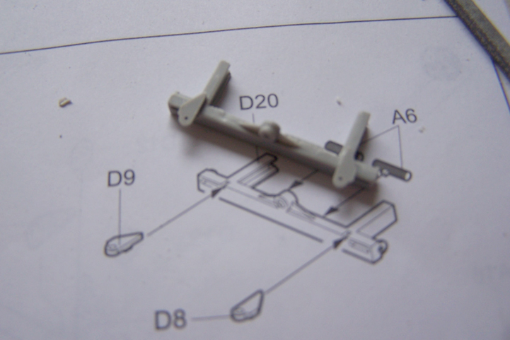
First up the axle and leafspring


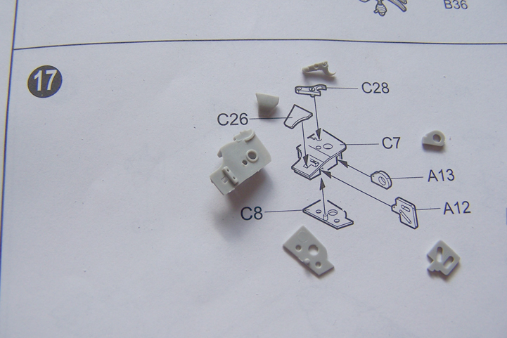
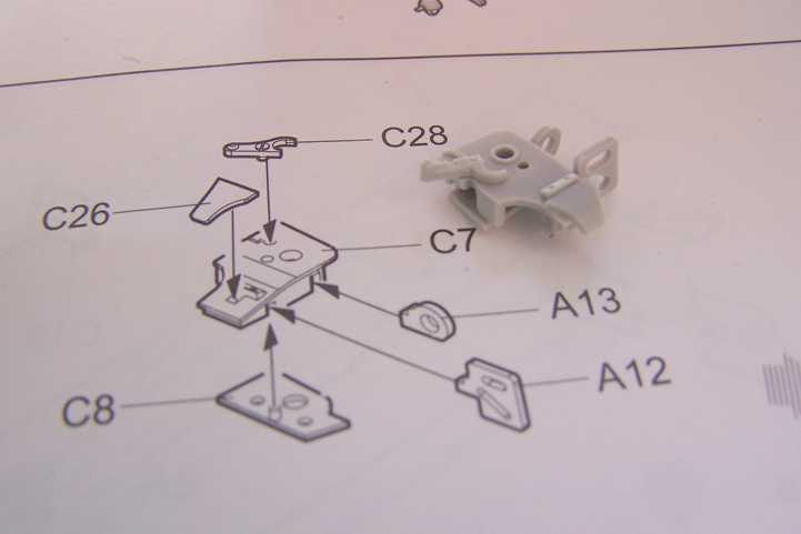
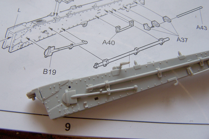
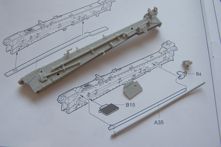
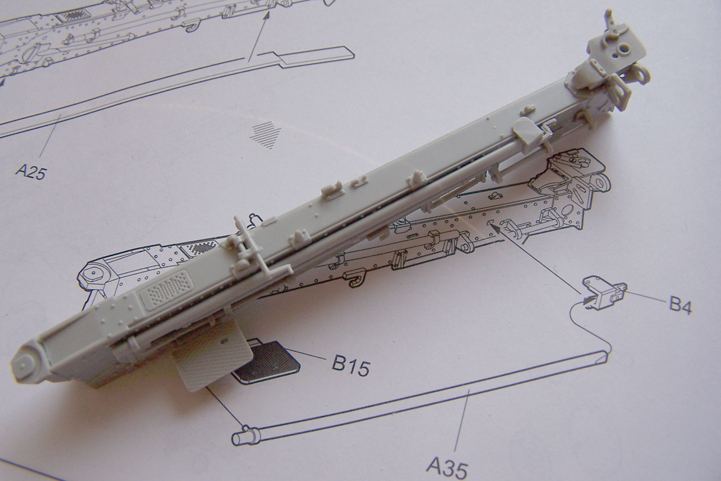
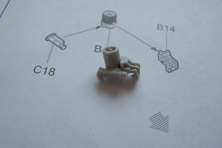
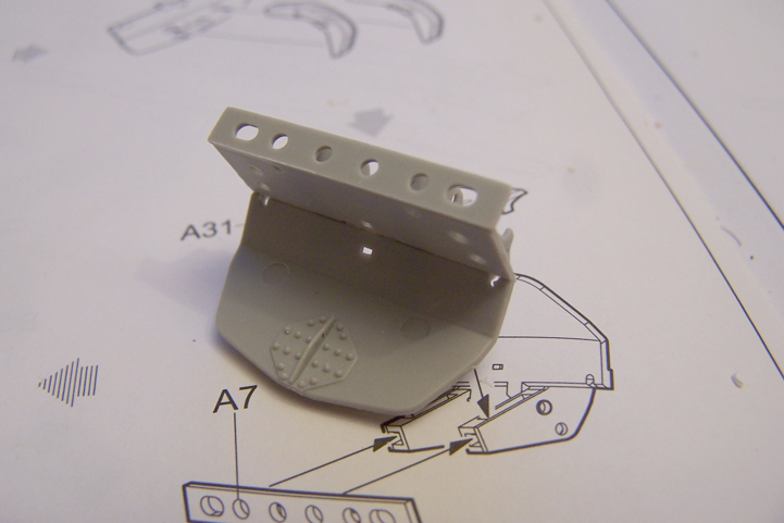
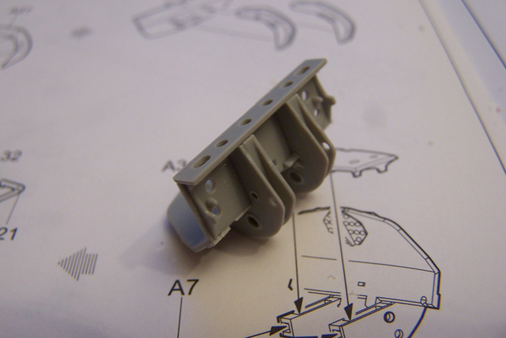
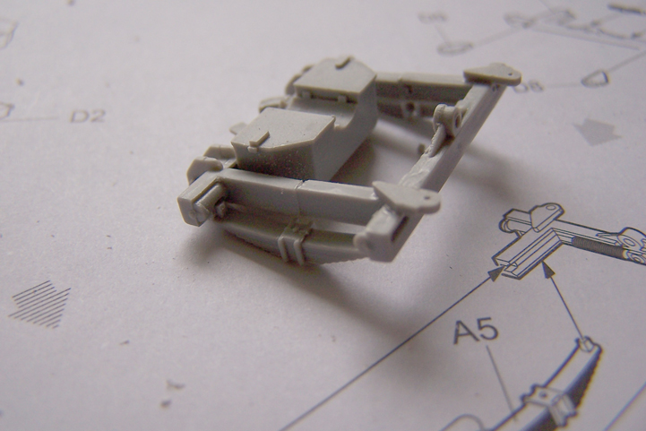
Then onto the thing that goes on to the front of the carriage An amount of 7 parts is needed to complete this step.

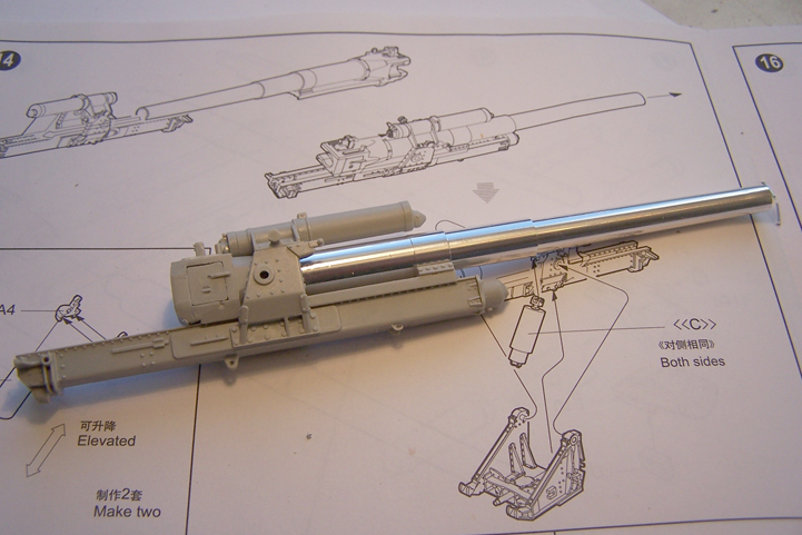
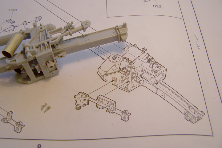
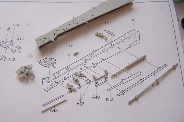
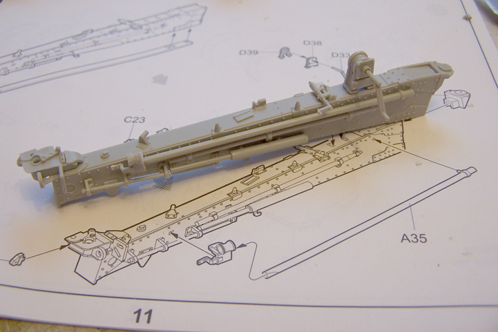
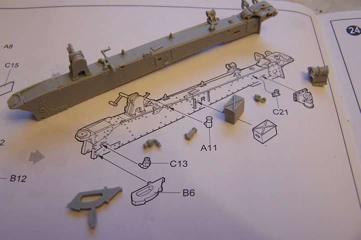
And a picture of subassemblies and the carriage


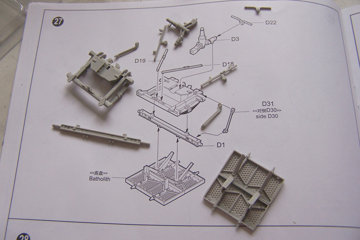
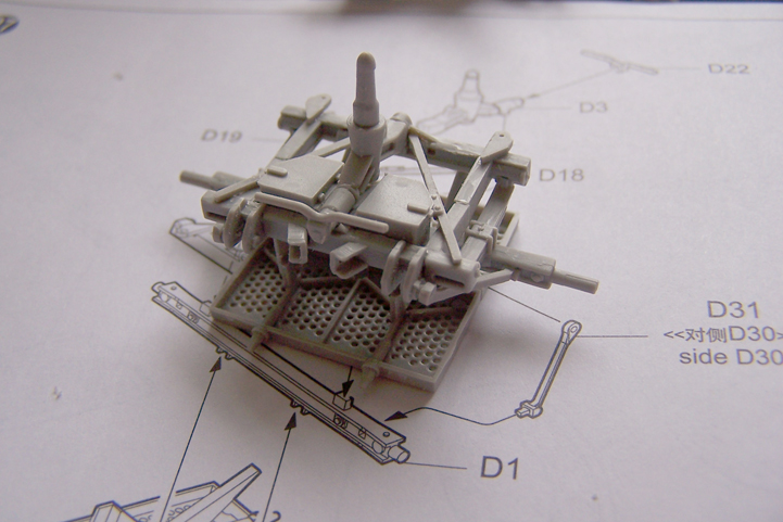
On to step 4
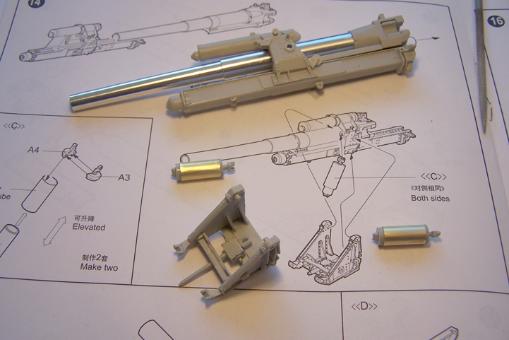
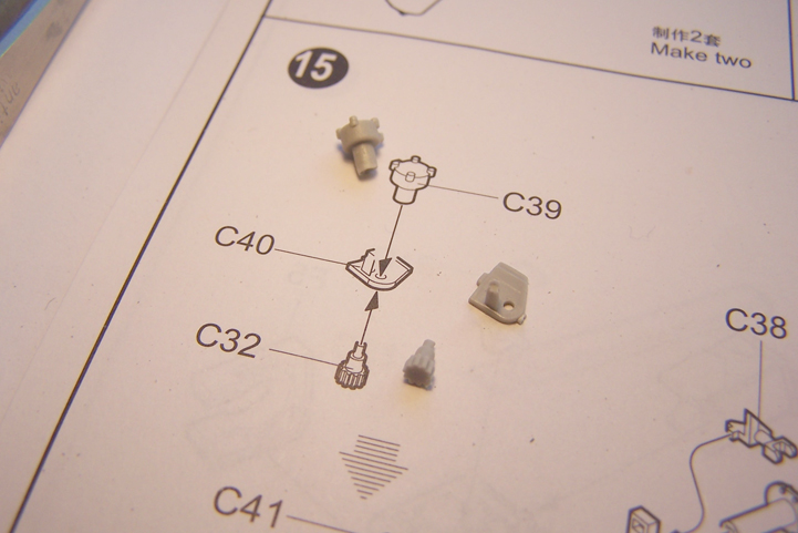
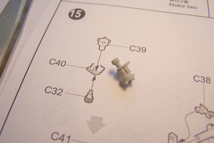
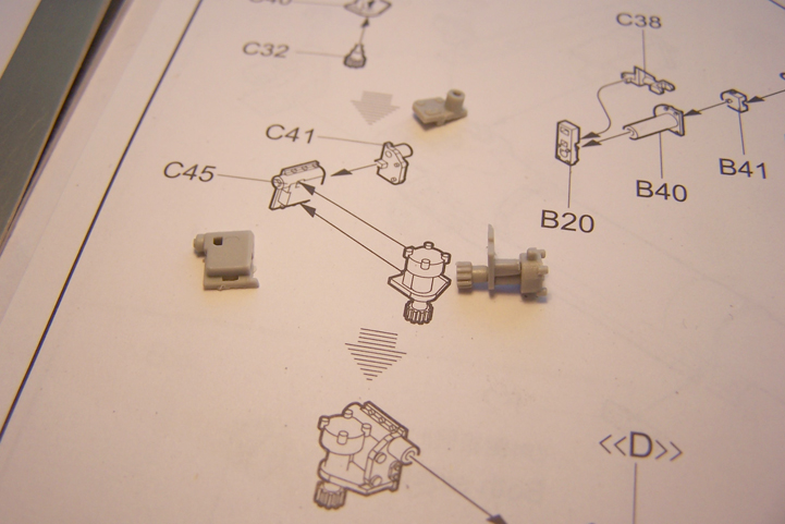
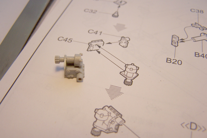
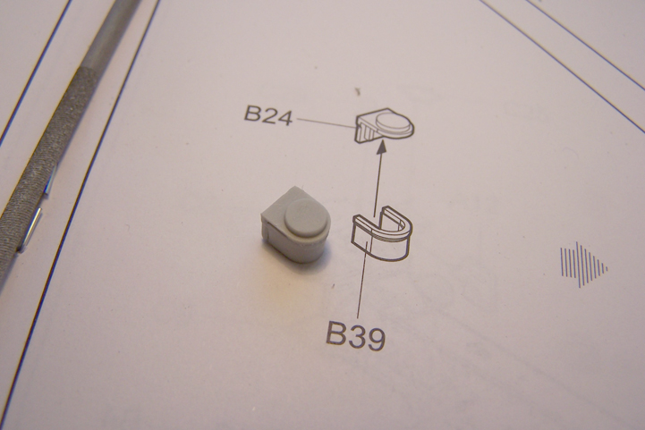
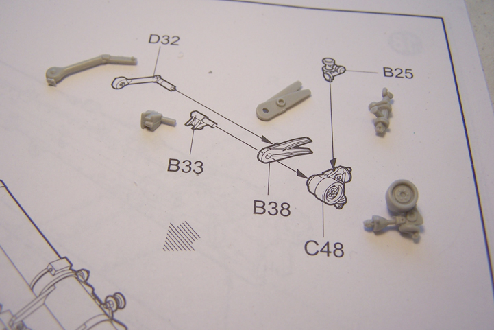
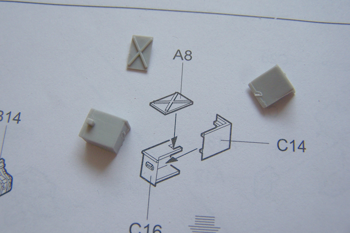
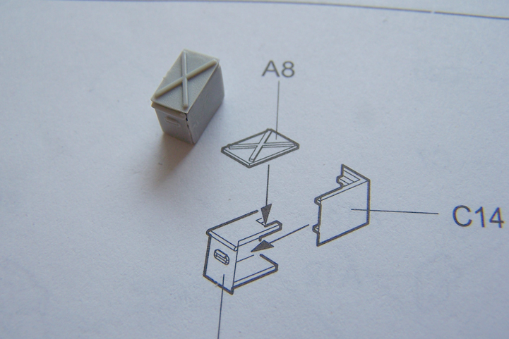
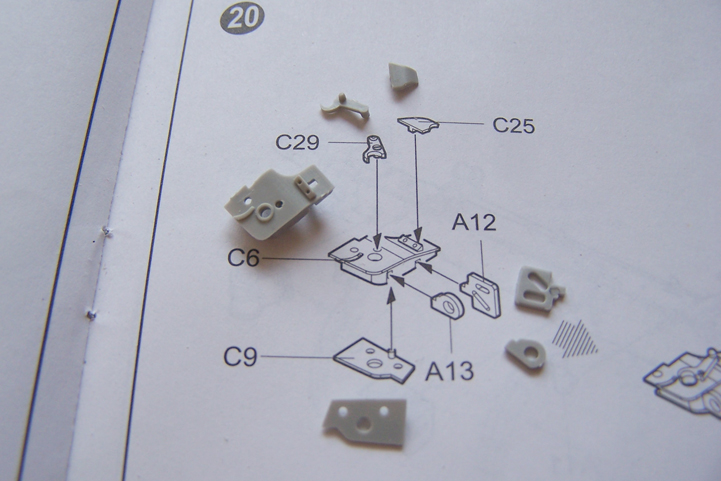
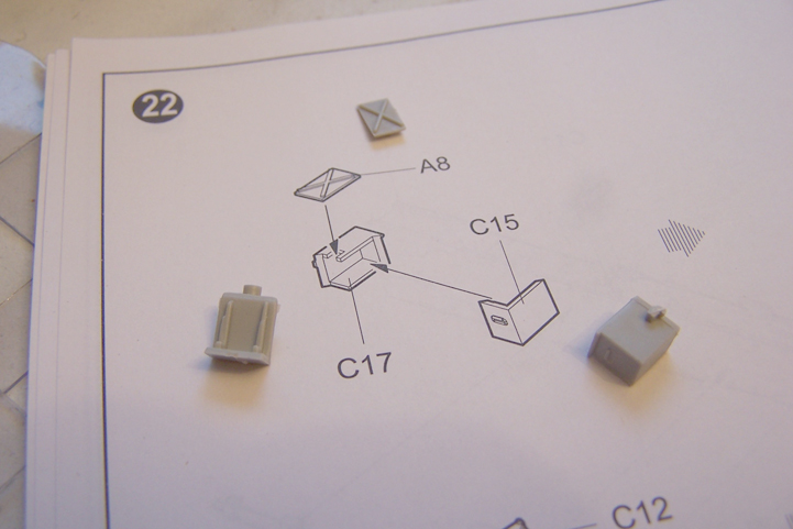
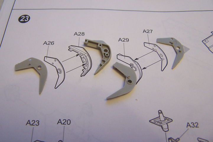
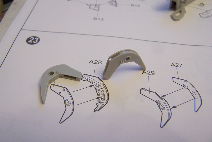
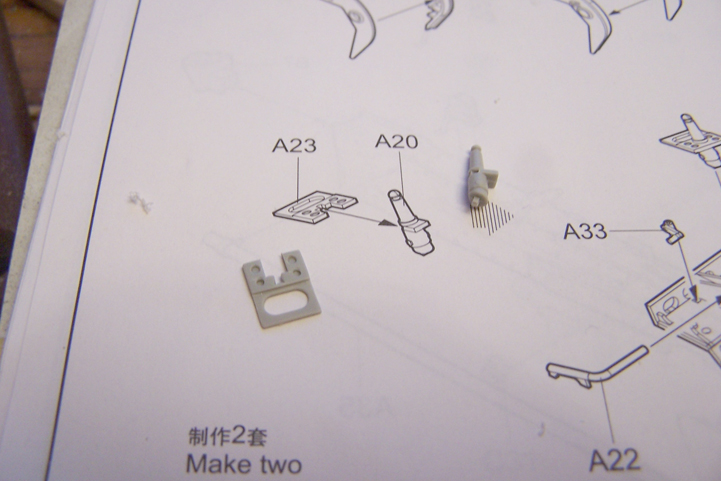
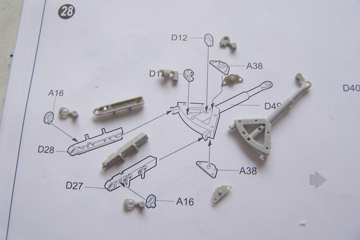
Step 4 is basically all about the parts that go on the axle inbetween the wheels and the carriage. Starting off with some sort of hydraulic device consisting of 3 parts. You need to make 2 of those but make them separate since they appear on both sides and they are thus mirrored.


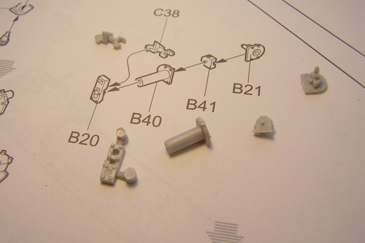
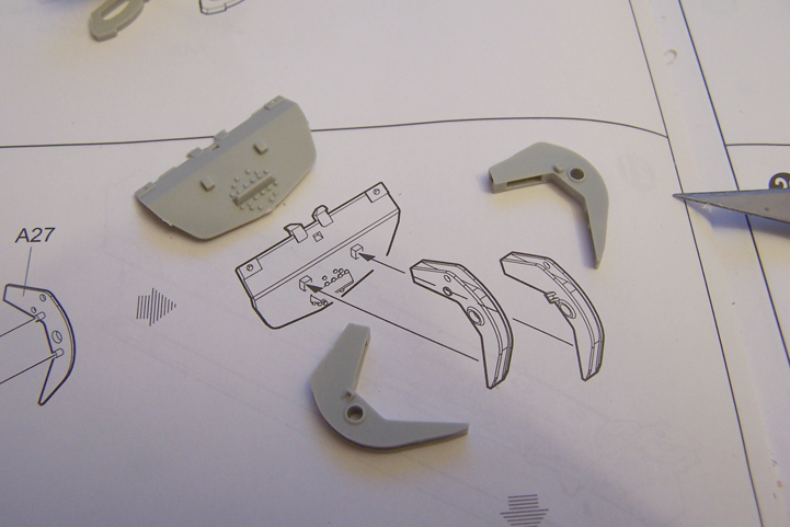
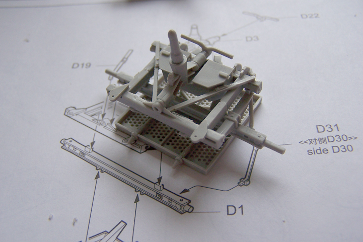
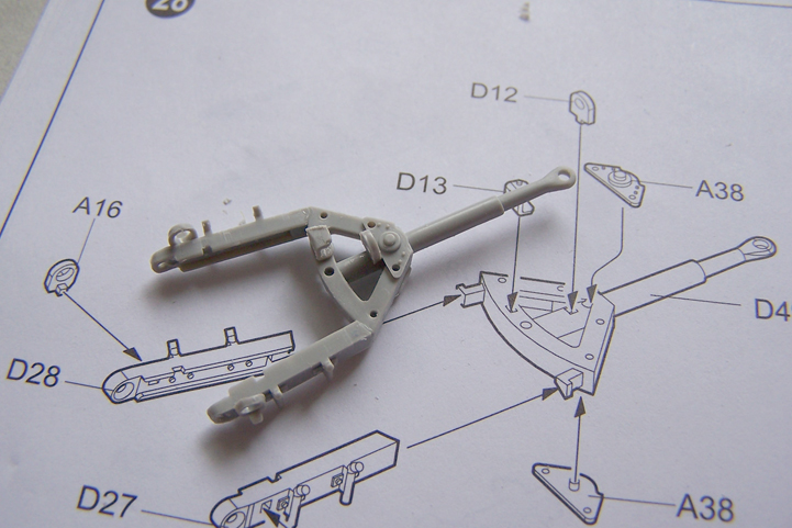
Next up the part attached to a plate and added with a break lever? and another small part which later gets a rod added to it. The breaklever has a couple of ejectorpinmarks on one side. Which needs to be filled and sanded. Again due to the size of the pinmarks I decided to go the CA route.


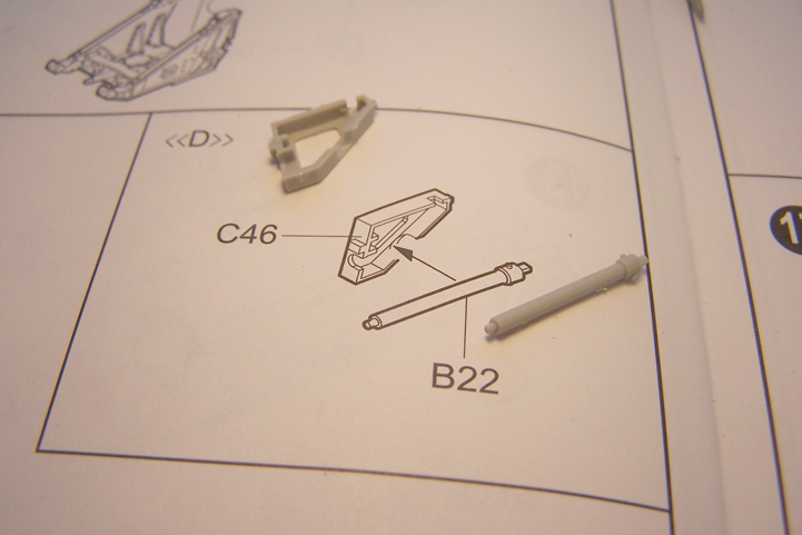
And the other hydraulic part for the other side


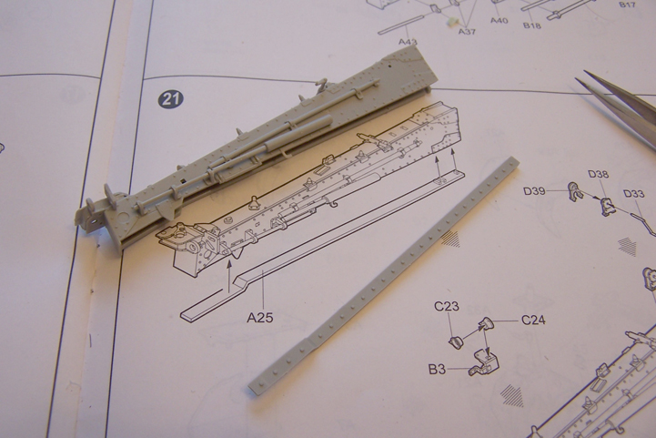
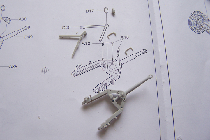
And putting the 2 subassemblies on to the axle. It was at this point I found out I misread the instructions again. Since I mounted the axle wrong way round. This way you either have the breaklever upside down or at the wrong side. So some carefull operation was needed to get the axle out again turn it around. and I had to turn the leafspring around too in this action but it all came good in the end.


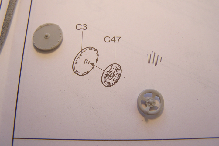
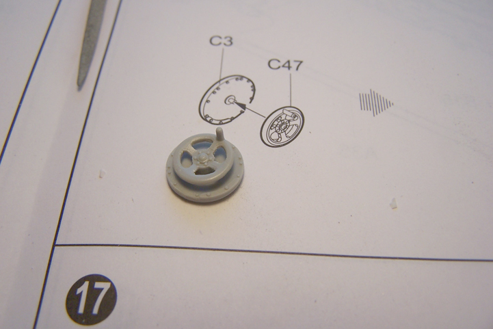
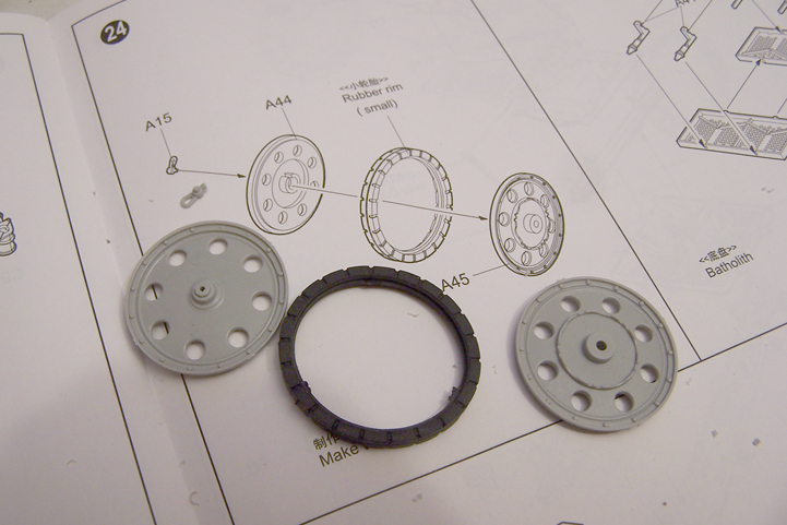
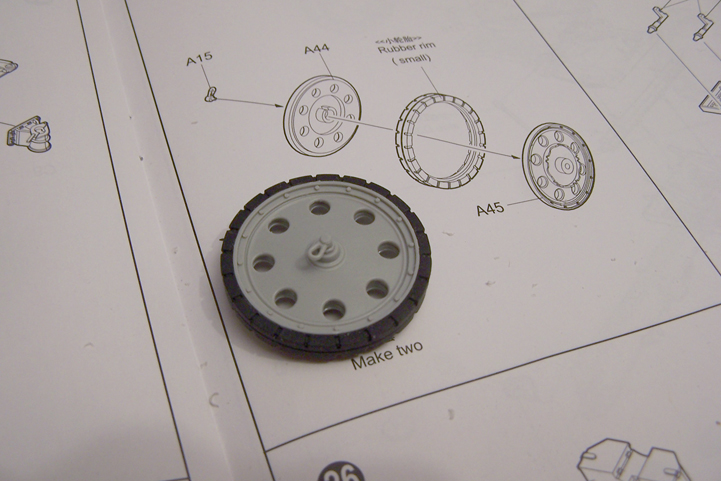
So far this update... Nice kit with some nice details. And it builts good so far. Next up will be of course the rest of the gun but I'm going to start with the wheels.
With friendly greetz
Robert Blokker