Hello all,
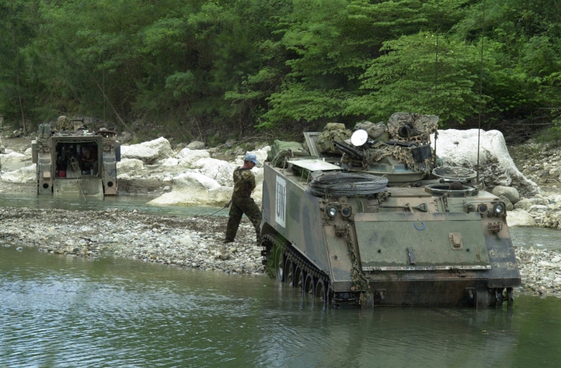
I am currently building a M806A1 ARVL (Armoured Recovery Vehicle Light) in Australian service.
This is my first ever build log and I guess the reason why I am doing it is that my reference pictures are not 100% as good as I would like so I would like to learn from peoples comments as I go along so I can get the details right.
For the build I am using the Academy M113A3 Iraq 2003 13211 as the base. The main reason why I chose this kit when compared to the Academy M113A1 kit is that I wanted to see what other goodies came in the kit. There are some items here that are useful like the binoculars, modern Alice style backpacks and other stuff which all went into my spares bin. The kit does have all the bits in it you need to backdate a model to the A1 standard.
The academy M113 kits are to be quite frank not that great. The molds are old and details are sloppy and oversimplified in places. Given that the kit I am using on this project is supposed to be an A3 standard vehicle some of the details are just plain wrong. All those comments aside the Academy offering is the best M113 on the market today. I do hope one day someone will bring us a better M113A1!
Other items I’m using to model the ARVL, correct kits inaccuracies and also get the Australian mods right are:
Aussie Armour:
352 M113A1 ARVL conversion with Photo etched parts
353 M113A1 APC/LRV (am using the aust style cargo hatch)
354 Radio Installations for M113A1
356 Austeyr rifles
357 5 Aussie packs and 8 pouches
Mouse Armour:
MA301 M113 fuel tank (1)
MA308 1/35 Australian M113A1 indicator lights and tow shackles
MA313 1/35 M113A1 engine deck mesh
MA312 1/35 Jackie Boxes
MA302 Australian Pattern Plastic jerrycans
Maple Leak Models
MLM1004 M113A1 ARVL Conversion
MLM1005 M113A1 Interior Upgrade Set
MLM1011 Worn M113 Roadwheels
MLM1012 Spare M113 Roadwheels
Eduard
35406 M113 Photoetch
I’m a bit of a slow builder so please bear with me; it may be a while between posts. All comments, suggestions and tips are welcome. So here goes.
Have spent a while cleaning up the old academy hull.
1. I cut a notch into the hull where there is a distinct join and weld seam between two armour panels.
2. I ground off the 2nd shock absorber. A1 M113s have shockys on only the 1st and 5th roadwheels. A2s onwards have shockys on the 1st, 2nd and 5th. I also have ground off the locating lugs for the track shrouds and filled the prominent hole in the front right sponson.
3. Installed the excellent Mouse Armour M113 fuel tank. The kit supplied fuel tank is inaccurate for all but the earliest M113 gasoline vehicles. The Mouse House fuel tank represents that factory installed tank and as such will work in a US, Canadian etc. vehicle. I have detailed this area with lead wire and plastic stock and a Maple Leak Model’s ramp cable pulley assembly. Also note the sponson reinforcement plates modeled from white plastic stock.
4. Rear right sponson details include bilge pump pipe, fuel supply pipework and conduit which travels along the right sponson wall. And finally the sponson reinforcement plate.
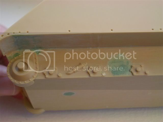
5. Corrections to the fire wall. The kit comes with a fire wall which includes a 1 piece engine access hatch, however early in the production run this was modified to a 2 piece engine access hatch arrangement which is common to almost all M113s used across the world. Also note I have removed the cdr’s 2298 radio junction box (where the green putty mark is). I will replace this later in the build with the Aussie Armour Radio Installation components. These are more accurate and allow the use of lead wires to represent the wires use on the real thing. Finally note the ventilation panel added to the top left corner. This appears to be an Aust specific mod I have seen it in many aust vehicles.
6. Glacis plate lights assembly. I am doing this work early in the project as I intend to mount the pivot control’s assemblies on the reverse side of the glacis plate so I wanted to get the front details sorted and then sealed up all the holes before I start on the interior details. The right hand lights require allot of work as they come in the academy kit all mounted on a single strip of plastic which is quite visibly incorrect. The Eduard PE approach also results in a highly visible strip of PE located on top of the glacis plate which is also inaccurate.
My approach to fixing the right hand lights starts with sealing up the slot for the supplied light strip. I don’t like to use evergreen styrene strip (the white stuff) for this task, it’s too soft and does not form a good base for mounting the lights on. I prefer to use scrap plastic from the kit to seal up the slot, it’s denser and forms a more robust surface to drill into when drilling holes for locating the lights.
Once the slot is filled I grab some individual M113 style lights from the spares bin (most M113 kits come with a few spare M113 lights). For the blackout lights I drill a hole for brass wire to mount in holes to be drilled in the glacis plate. Why brass? So if I get the angle wrong I can bend it a little to correct. Now I drill the holes in the now filled slot on the glacis plate for mounting the lights. Also note I have drilled out a plug for fuse wire to represent the lights wiring. There are 2 such plugs in between the black out light and IR light and in-between the IR light and normal light. (If you don’t have enough spare individual M113 lights you can always just drill out the kit supplied ones supplied on the strip and mount them on brass wire like I have with the back out light on the far left)
I have also drilled out the headlight lenses so that later I can mount some MV lenses.
Finally I filed down the brush guard to a more scale thickness (I think this approach creates a more accurate depiction of the lights than the kit or Eduard Photoetch option). Not 100% accurate but pretty close.
I’ll install the Aust style indicators later in the build. Note indicators on a ARVL are mounted on the brush guard (but more on that later)
Also a shot of the back of the glacis plate. It shows all the filling and detail work in greater depth. The wires will eventually be visible disappearing behind the vehicle instrument panel - perfect!!!
7. A shot of the driver's bay. Note access panels in the floor. These give access to the torsion bars under the floor. Note the driver’s seat pedestal. In the academy kit this is depicted mounted to the floor of the vehicle and is incorrect. The seat is actually mounted to the sponson wall and does not touch the vehicle floor. Also note the mount the driver’s seat pedestal is at an slight angle to the sponson wall not at right angles as depicted in the kit.
8. Finally a shot of the driver's bay details. Note all the assemblies are blue tacked in place. Any comments of their placement would be welcome?
Pictured here is the bilge pump pipe, Instrument panel, fuse box, mount for the night driving sight mount (when not is use), driver's F88C, driver's 2298 (radio and intercom box) and vehicle engine fire extinguisher system.
Have not yet finished detailing the sticks.
Comment, suggestions observations are welcome.
Hosted by Darren Baker
M806A1 ARVL in Australian service
WayneB
Victoria, Australia
Joined: July 22, 2008
KitMaker: 141 posts
Armorama: 130 posts
Joined: July 22, 2008
KitMaker: 141 posts
Armorama: 130 posts
Posted: Sunday, February 22, 2009 - 07:37 AM UTC
newfish
England - West Midlands, United Kingdom
Joined: June 23, 2008
KitMaker: 2,329 posts
Armorama: 2,110 posts
Joined: June 23, 2008
KitMaker: 2,329 posts
Armorama: 2,110 posts
Posted: Sunday, February 22, 2009 - 07:54 AM UTC
Wayne that looks superb so far I really like the changes you've done to the kit!.
I will be following this with great intereast.
WayneB
Victoria, Australia
Joined: July 22, 2008
KitMaker: 141 posts
Armorama: 130 posts
Joined: July 22, 2008
KitMaker: 141 posts
Armorama: 130 posts
Posted: Saturday, March 21, 2009 - 11:05 AM UTC
Hello all,
A bit more progress on my ARVL.
Most of the details are just tacked into place at the moment whilst I get my stowage figured out. Will glue most of it in place once I have painted and weathered.
Comments welcome
Inside of the glacis plate with the pivot controls.
Modified interior roof details.
Fire wall for driver bay.
Right hand sponson.
Drivers bay and left hand sponson.
Drivers bay.
A few more details to go and then I will strip out the tacked in details and paint and weather. Will fit the 1780 and wires for the radios after painting.
newfish
England - West Midlands, United Kingdom
Joined: June 23, 2008
KitMaker: 2,329 posts
Armorama: 2,110 posts
Joined: June 23, 2008
KitMaker: 2,329 posts
Armorama: 2,110 posts
Posted: Saturday, March 21, 2009 - 11:59 AM UTC
Nice work Wayne .
Your scratch building is impressive!. I like some of the stowage you've added
jasmils
Queensland, Australia
Joined: December 23, 2003
KitMaker: 1,016 posts
Armorama: 745 posts
Joined: December 23, 2003
KitMaker: 1,016 posts
Armorama: 745 posts
Posted: Saturday, March 21, 2009 - 03:53 PM UTC
What!!!! No thumb guards on the Lat's!!!!
Very nice Wayne.
Dio????
Jason
Very nice Wayne.
Dio????
Jason
ALBOWIE
New South Wales, Australia
Joined: February 28, 2006
KitMaker: 1,605 posts
Armorama: 1,565 posts
Joined: February 28, 2006
KitMaker: 1,605 posts
Armorama: 1,565 posts
Posted: Saturday, March 21, 2009 - 10:25 PM UTC
Quoted Text
Hello all,
A bit more progress on my ARVL.
Most of the details are just tacked into place at the moment whilst I get my stowage figured out. Will glue most of it in place once I have painted and weathered.
Comments welcome
Inside of the glacis plate with the pivot controls.
Modified interior roof details.
Fire wall for driver bay.
Right hand sponson.
Drivers bay and left hand sponson.
A few more details to go and then I will strip out the tacked in details and paint and weather. Will fit the 1780 and wires for the radios after painting.
Nice interior but if you are modelling my old car (88 of 101st FD Wksp/1 BASB) then the left hand sponson is incorrect. There is a Hydraulic tank on the left sponson and the radios are in a Vertical rack like a bookcase at the front of the right Sponson in front of where you have the hydraulic tank. I have recollections of our one being a lot lower profile and opposite of wher you have it but my memory is not what it used to be. 88 only carried 46 sets (524's) and the 1780 was mounted on the forward bulkhead just below and to the left of the commander cupola. She always had three AMU fitted though (spare) Unfortunately I don't have any pics of her interior as these were lost/misplaced by the late Lindsay Sparkes.
The cam net was rolled into a tarp in about a 1.5 m square about 0.5m high that sat on the middle of the rear roof where the cargo hatch is located. A series of metal tubes made up the cam poles and these were carried in a rack that ran parrallel to the left sponson. These were 25 mm/1"" square tube
Should look great at the rate you are going.
we mounted two bars to the Ramp release actiuators at the front and back going across the vehicle which had hammocks tied of permanantly. The Driver slept on the toolboxs on the right sponson and I slept in a hammock on the left.
Can't wait to see this one finished.
Cheers
Al
WayneB
Victoria, Australia
Joined: July 22, 2008
KitMaker: 141 posts
Armorama: 130 posts
Joined: July 22, 2008
KitMaker: 141 posts
Armorama: 130 posts
Posted: Sunday, March 22, 2009 - 03:22 AM UTC
Gary,
Thanks for the comments on the pivots. The sad part is that most of it will be invisible once assembled.
W
Thanks for the comments on the pivots. The sad part is that most of it will be invisible once assembled.
W
WayneB
Victoria, Australia
Joined: July 22, 2008
KitMaker: 141 posts
Armorama: 130 posts
Joined: July 22, 2008
KitMaker: 141 posts
Armorama: 130 posts
Posted: Sunday, March 22, 2009 - 03:22 AM UTC
Jason,
Thumb guard on the lats? Any idea what year that mod came in? I think I know what you’re talking about from pictures but just can’t really remember them on carriers when I was in.
W
Thumb guard on the lats? Any idea what year that mod came in? I think I know what you’re talking about from pictures but just can’t really remember them on carriers when I was in.
W
WayneB
Victoria, Australia
Joined: July 22, 2008
KitMaker: 141 posts
Armorama: 130 posts
Joined: July 22, 2008
KitMaker: 141 posts
Armorama: 130 posts
Posted: Sunday, March 22, 2009 - 03:23 AM UTC
Al,
Thanks for commenting I was hopeing you'd chime in on this thread. It's great to have a RAEME spanner/radio mechanic on this discussion group as I think I have only ever spent about 30 seconds in an ARVL.
I must admit I’m a bit confused on the radios. I was toying with laying them out like this based or your advice.
However a bunch of photos of different Aust ARVLs I have always seen the hydraulic system reservoir in the front right sponson. So it would look something like this.
The only detailed set of pictures I have for the ARVL is a Canadian vehicle at: http://good-times.webshots.com/album/563768805zrquIq So when I found the below photo I thought there would not be enough room forward of the reservoir for radios. In an aust vehicle the crew heater would not be there but I’m thinking we would probably have the hydraulic system oil filter shown in this picture…. The Canadian radios are laid out like these:
A bunch of photos of Australian vehicles show a layout like the below, but the details are just that little bit out of reach.
One thing I’m thinking; was your vehicle, with the radios in the right hand sponson and the 1780 on the firewall neat the CDR cupola, a Fitters track? Photo below:
Just hoping to get things right here. Many thanks for the advice mate it is appreciated!!!!
W
WayneB
Victoria, Australia
Joined: July 22, 2008
KitMaker: 141 posts
Armorama: 130 posts
Joined: July 22, 2008
KitMaker: 141 posts
Armorama: 130 posts
Posted: Sunday, March 22, 2009 - 05:15 AM UTC
James,
Thanks for the encouragement
W
Thanks for the encouragement
W
ALBOWIE
New South Wales, Australia
Joined: February 28, 2006
KitMaker: 1,605 posts
Armorama: 1,565 posts
Joined: February 28, 2006
KitMaker: 1,605 posts
Armorama: 1,565 posts
Posted: Sunday, March 22, 2009 - 02:14 PM UTC
Quoted Text
Al,
Thanks for commenting I was hopeing you'd chime in on this thread. It's great to have a RAEME spanner/radio mechanic on this discussion group as I think I have only ever spent about 30 seconds in an ARVL.
I must admit I’m a bit confused on the radios. I was toying with laying them out like this based or your advice.
However a bunch of photos of different Aust ARVLs I have always seen the hydraulic system reservoir in the front right sponson. So it would look something like this.
The only detailed set of pictures I have for the ARVL is a Canadian vehicle at: http://good-times.webshots.com/album/563768805zrquIq So when I found the below photo I thought there would not be enough room forward of the reservoir for radios. In an aust vehicle the crew heater would not be there but I’m thinking we would probably have the hydraulic system oil filter shown in this picture…. The Canadian radios are laid out like these:
A bunch of photos of Australian vehicles show a layout like the below, but the details are just that little bit out of reach.
One thing I’m thinking; was your vehicle, with the radios in the right hand sponson and the 1780 on the firewall neat the CDR cupola, a Fitters track? Photo below:
Just hoping to get things right here. Many thanks for the advice mate it is appreciated!!!!
W
Your right, I was discussing this with a friend who thought I was muddling it up between them, I got muddled between the Fitters and ARVL. Both the fitters and ARVL had the radios at the front of the right Sponson with 50 cal stowage below them. We had two 524's fitted one above the other. We had a Bin Pack in the left sponson and crew stowage on the shelf (maybe the bin pack is what i am thinking of? None of the Fitters or ARVL's I served on had 160's they all had 46/47 sets then RAVEN. The 1780 was on the front wall as I used to smash my knee on it when my driver got carried away and I have a recollection of recabling the car when we did a major service and relocating it to the left wall.
I can't remeber having F88 racks either as we had just been issued with the F88C when I joined the unit. All the A vehicle crews were issued a Browning & F88C as pers weapons. THe Brownings were carried in locally purchased Black leather Shoulder Holsters. CVC's were mandatory for all my crews.
Cheers
Sorry to scare you.
Al
jasmils
Queensland, Australia
Joined: December 23, 2003
KitMaker: 1,016 posts
Armorama: 745 posts
Joined: December 23, 2003
KitMaker: 1,016 posts
Armorama: 745 posts
Posted: Sunday, March 22, 2009 - 07:14 PM UTC
Wayne, I'm working on a pic of the thumb gaurds for you. And to be honest, I was being a smart a**e.
The radio fit out in the ARVL/Fitters would have been like the LR110 FFR, wouldn't it Al?
Jason
The radio fit out in the ARVL/Fitters would have been like the LR110 FFR, wouldn't it Al?
Jason
ALBOWIE
New South Wales, Australia
Joined: February 28, 2006
KitMaker: 1,605 posts
Armorama: 1,565 posts
Joined: February 28, 2006
KitMaker: 1,605 posts
Armorama: 1,565 posts
Posted: Sunday, March 22, 2009 - 10:29 PM UTC
The radio fit was literally 1/4" Alloy plate welded like a bookcase with shelves to which the 1029's were bolted. The ARVL one had the hydraulic connections where the bottom Ammo stowage would have been and the two top shelves filled with 524's or a 524 and an empy 1029 mounting tray. When we only had one radio we tended to use the middle tray as the top one caused too much heat build up and i was forever readjusting the Squelch settings.
My memory is slowly coming back from 15 years ago and this is a great example of you can't always go off what a vet says.
Sorry for the confusion Wayne.
I'm really looking forward to seeing this one. If you do 88 then her name was "REICHFUHRER" and removed in 94 when we became 1 BASB (1/10 markings - the tac plate for 101 also happened to be 88). The RSM hated Spanners and had us remove all our vehicle names. THe ARVL technically belonged to Recovery PL and two of the Fitters tracks 88A &88B belonged to Vehicle Platoon whilst the third Fitters belonged to the Forward Repair Group (88C or F depending on exercise) as did I at the time as the ART Tels. We only served as a functional group during Brigade level Exercises but I was put in charge of all A Vehicle related activities including Training. Thanks to the Readies we actually got so much ammo for the 50 Cals that we could have the whole unit have a Shoot and have enough left to do Battle runs - a rarity in RAEME units where you were lucky to get a liner a gun. The 50's hadn't been fired in over three years before i got there and were in the most part incomplete or unserviceable.
ptruhe
Texas, United States
Joined: March 05, 2003
KitMaker: 2,092 posts
Armorama: 1,607 posts
Joined: March 05, 2003
KitMaker: 2,092 posts
Armorama: 1,607 posts
Posted: Monday, March 23, 2009 - 03:57 AM UTC
Fantastic amount of detail. For some reason the laterals look a bit close to the seat but the memory is fuzzy.
Are the commo hookups a commercial item or something you created?
Paul
Are the commo hookups a commercial item or something you created?
Paul
WayneB
Victoria, Australia
Joined: July 22, 2008
KitMaker: 141 posts
Armorama: 130 posts
Joined: July 22, 2008
KitMaker: 141 posts
Armorama: 130 posts
Posted: Sunday, April 05, 2009 - 05:36 AM UTC
Paul,
The laterals are too close to the seat. Thanks mate. I hadn’t spotted that. I’ll move them.
Al,
Thanks for the help on the radios. The funny thing is that my memory of the vehicle had them in the front right sponson stacked vertically however I have only been inside one once so I used the reference material posted above to convince myself that my memory was wrong…. So I appreciate your advice.
Have mocked up a basic shelf layout with plastic card. Most is hidden by the hydraulic reservoir anyway. Note I have had to shave some height off both 1029 mounting trays to create enough room for the shelves but I think it looks ok. I did want to mount 2 radios in my vehicle and I decided to go with a 524 and a 77 set as my regiment never had enough operational 524s so only troop leaders would get 2 x 524s. What’s a vehicle mounted 77 set called again?
I decided to move the hydraulic system filter down onto the sponson wall (blue tacked in place) as I there is no room for it anymore attached to the hydraulic reservoir now that the radios are in place, I could not figure our any other place for it to go.
I have placed the winch counter balance valve (rectangular boxy thing on the engine firewall next to the 77 set). The MLM instruction shows it located here. So I placed the 1780 and 2298 on the firewall from right to left next to it.
Attached below is my mock up of the placement of the hydraulic system and radio components. Have predrilled hoes for the all hydraulic / radio lines and wires but I will have to wait until after painting the interior and assembly to install the lines themselves as they will attach to quite a few subcomponents that I need to keep separate for painting.
Now it’s just the long slog to get through the rest of the interior minor details to get to painting! Lots of wiring and titch components!
Any comments or suggestions welcome?
W
WayneB
Victoria, Australia
Joined: July 22, 2008
KitMaker: 141 posts
Armorama: 130 posts
Joined: July 22, 2008
KitMaker: 141 posts
Armorama: 130 posts
Posted: Sunday, May 31, 2009 - 04:42 AM UTC
Paul,
Sorry mate I missed your question. The radio harness is an Aussie Armour product 354
Radio Installation for M113A1 http://www.mheaust.com.au/index.html. It a useful product as it can be used on most 70's and 80's vintage US vehicles. Verlinden have a similar offering but I dont think they offer the 2298 crew boxes.
W
WayneB
Victoria, Australia
Joined: July 22, 2008
KitMaker: 141 posts
Armorama: 130 posts
Joined: July 22, 2008
KitMaker: 141 posts
Armorama: 130 posts
Posted: Sunday, May 31, 2009 - 05:35 AM UTC
Hello all,
Figured I’d take a few last photos of the interior of my ARVL before I coat it all in primer. Most details are still tacked in place to be removed for ease of painting.
Interior
One interesting detail here is the collapsible footrest for the drivers left foot shown (in the first shot below). The mod was added to all Aust M113 FOVs as a result experience from mine damage in Vietnam.
I also took a crack at detailing the periscopes. Nothing major as they will barely be visible through the hatches but I wanted to get the wing nuts in as they are quite distinctive.
Mud guards
A few shots of the indicators which are mounted in the mudguards of ARVLs as they would be blocked by the spades if mounted in the standard position near the tail lights.
Note I have enclosed the mudguards and mounted them slightly lower than the academy kit instructions state they should be mounted. I picked up this trick at Mick Toal’s current Carried Away by Rwanda Carriers thread https://armorama.kitmaker.net/forums/129839&page=3
Thanks for the tip Mick, without it I would not be able to mount the ARVL spades properly which could have been very frustrating indeed.
Roadwheels.
The first shot below shows an unmodified academy roadwheel on the left. Note the prominent raised rim where the rubber would be vulcanized onto the roadwheel. I have never seen this rim on an Aust M113 and can’t say I have ever seen it on a picture of any foreign M113s. There are stories of the rim being present on US M113 in Germany in the 80’s (apparently from local suppliers) but I have never seen any photos myself.
I removed the rim from all my roadwheels and added a few nicks and scuffs to the rubber portion of the roadwheel as shown on the right.
Below is a photo of some examples of Maple Leaf Models products:
Top - 1 x Spare M113 roadwheel
Bottom - 2 x Worn M113 roadwheels: on the bottom left is an unmodified worn roadwheel and on the bottom right is a worn roadwheel with the raised rim sanded off.
Maple Leafs worn roadwheels set is really neat.
Roadwheels like any rubber component wear out. At an early stage the rubber portion of the roadwheel has minor pits and chunks removed by abrasion and rocks. Later as the wear gets worse and whole segments of rubber fall away in a process referred to as chuncking. If memory serves me correctly any more than 10-20% chuncking means that the crew need to change the roadwheel – Not an easy task.
The Maple Leaf Models Worn M113 roadwheels kit includes 5 outside roadwheels and a 5 inside roadwheels in varying degrees of disrepair. Roughly half the wheels have minor damage and the other half have major chunking to a level which indicates the wheels will need to be replaced soon. The set should last about 2 M113 vehicles as the worn wheels can be mixed with the kits undamaged wheels. The quality of the sculpting is excellent and depicts chunking and wear in a way that is beyond my crude ability to replicate. Casting is acceptable with some bubbles and incompletely filled molds which are within the average modeler’s ability to repair.
DAR
United Kingdom
Joined: April 27, 2002
KitMaker: 250 posts
Armorama: 188 posts
Joined: April 27, 2002
KitMaker: 250 posts
Armorama: 188 posts
Posted: Sunday, May 31, 2009 - 06:13 AM UTC
Nice work Wayne. I'd completely missed the tip about the mud guards, hopefully I'll be able to prise off the mounting points for the spades.
WayneB
Victoria, Australia
Joined: July 22, 2008
KitMaker: 141 posts
Armorama: 130 posts
Joined: July 22, 2008
KitMaker: 141 posts
Armorama: 130 posts
Posted: Sunday, May 31, 2009 - 12:46 PM UTC
Marcel
The Maple Leaf Models (MLM) ARVL set didn’t provide all the details needed for an Australian ARVL. Big items which were provided by the Aussie Armour Kit include the floatation pods, trafficators, trim vane and cargo hatch with air filters. One big plus in the MLM kit is that it provides a full interior. So I needed both kits.
Interestingly the rear spade details are different on the Canadian and Aust ARVLs. The Canadian ones have oval shaped holes for the taillights, Aust ones have round holes.
Sadly however the MLM kit has gone out of production.
So I have both sets and am picking the best bits of both. The MLM molds were very old by the time my kit got poured. MLM was good enough to warn me before I bought the kit, so no problem. Its nothing that cant be fixed or scratchbuilt.
Cheers
W
trahe
Virginia, United States
Joined: April 03, 2006
KitMaker: 1,158 posts
Armorama: 950 posts
Joined: April 03, 2006
KitMaker: 1,158 posts
Armorama: 950 posts
Posted: Sunday, May 31, 2009 - 01:14 PM UTC
Wayne, great job! It's looking really good so far!
seb43
Paris, France
Joined: August 30, 2005
KitMaker: 2,315 posts
Armorama: 2,158 posts
Joined: August 30, 2005
KitMaker: 2,315 posts
Armorama: 2,158 posts
Posted: Sunday, May 31, 2009 - 03:11 PM UTC
Wayne
I miss your build but this is really impressive
Congrats
Seb
I miss your build but this is really impressive
Congrats
Seb
ptruhe
Texas, United States
Joined: March 05, 2003
KitMaker: 2,092 posts
Armorama: 1,607 posts
Joined: March 05, 2003
KitMaker: 2,092 posts
Armorama: 1,607 posts
Posted: Monday, June 01, 2009 - 03:13 AM UTC
Can't wait to see this after it's all painted up. Enjoying the to notch details like the periscope wing nuts, driver's hole pad and the filled in mud guard. Have you found the Academy driver's hatch to be a bit too small in outer diameter?
Thanks for getting back to me on the commo parts.
Paul
Thanks for getting back to me on the commo parts.
Paul
Blood_Raven117
Victoria, Australia
Joined: July 05, 2009
KitMaker: 13 posts
Armorama: 13 posts
Joined: July 05, 2009
KitMaker: 13 posts
Armorama: 13 posts
Posted: Friday, July 17, 2009 - 05:03 AM UTC
Bloody nice work on the interior Wayne