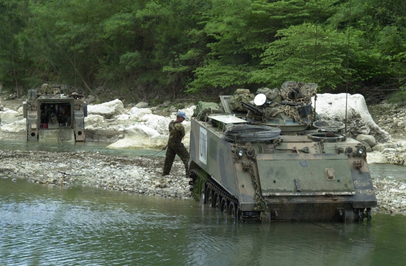
I am currently building a M806A1 ARVL (Armoured Recovery Vehicle Light) in Australian service.

This is my first ever build log and I guess the reason why I am doing it is that my reference pictures are not 100% as good as I would like so I would like to learn from peoples comments as I go along so I can get the details right.
For the build I am using the Academy M113A3 Iraq 2003 13211 as the base. The main reason why I chose this kit when compared to the Academy M113A1 kit is that I wanted to see what other goodies came in the kit. There are some items here that are useful like the binoculars, modern Alice style backpacks and other stuff which all went into my spares bin. The kit does have all the bits in it you need to backdate a model to the A1 standard.
The academy M113 kits are to be quite frank not that great. The molds are old and details are sloppy and oversimplified in places. Given that the kit I am using on this project is supposed to be an A3 standard vehicle some of the details are just plain wrong. All those comments aside the Academy offering is the best M113 on the market today. I do hope one day someone will bring us a better M113A1!
Other items Im using to model the ARVL, correct kits inaccuracies and also get the Australian mods right are:
Aussie Armour:
352 M113A1 ARVL conversion with Photo etched parts
353 M113A1 APC/LRV (am using the aust style cargo hatch)
354 Radio Installations for M113A1
356 Austeyr rifles
357 5 Aussie packs and 8 pouches
Mouse Armour:
MA301 M113 fuel tank (1)
MA308 1/35 Australian M113A1 indicator lights and tow shackles
MA313 1/35 M113A1 engine deck mesh
MA312 1/35 Jackie Boxes
MA302 Australian Pattern Plastic jerrycans
Maple Leak Models
MLM1004 M113A1 ARVL Conversion
MLM1005 M113A1 Interior Upgrade Set
MLM1011 Worn M113 Roadwheels
MLM1012 Spare M113 Roadwheels
Eduard
35406 M113 Photoetch
Im a bit of a slow builder so please bear with me; it may be a while between posts. All comments, suggestions and tips are welcome. So here goes.
Have spent a while cleaning up the old academy hull.
1. I cut a notch into the hull where there is a distinct join and weld seam between two armour panels.

2. I ground off the 2nd shock absorber. A1 M113s have shockys on only the 1st and 5th roadwheels. A2s onwards have shockys on the 1st, 2nd and 5th. I also have ground off the locating lugs for the track shrouds and filled the prominent hole in the front right sponson.
3. Installed the excellent Mouse Armour M113 fuel tank. The kit supplied fuel tank is inaccurate for all but the earliest M113 gasoline vehicles. The Mouse House fuel tank represents that factory installed tank and as such will work in a US, Canadian etc. vehicle. I have detailed this area with lead wire and plastic stock and a Maple Leak Models ramp cable pulley assembly. Also note the sponson reinforcement plates modeled from white plastic stock.

4. Rear right sponson details include bilge pump pipe, fuel supply pipework and conduit which travels along the right sponson wall. And finally the sponson reinforcement plate.

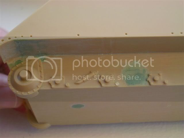
5. Corrections to the fire wall. The kit comes with a fire wall which includes a 1 piece engine access hatch, however early in the production run this was modified to a 2 piece engine access hatch arrangement which is common to almost all M113s used across the world. Also note I have removed the cdrs 2298 radio junction box (where the green putty mark is). I will replace this later in the build with the Aussie Armour Radio Installation components. These are more accurate and allow the use of lead wires to represent the wires use on the real thing. Finally note the ventilation panel added to the top left corner. This appears to be an Aust specific mod I have seen it in many aust vehicles.

6. Glacis plate lights assembly. I am doing this work early in the project as I intend to mount the pivot controls assemblies on the reverse side of the glacis plate so I wanted to get the front details sorted and then sealed up all the holes before I start on the interior details. The right hand lights require allot of work as they come in the academy kit all mounted on a single strip of plastic which is quite visibly incorrect. The Eduard PE approach also results in a highly visible strip of PE located on top of the glacis plate which is also inaccurate.
My approach to fixing the right hand lights starts with sealing up the slot for the supplied light strip. I dont like to use evergreen styrene strip (the white stuff) for this task, its too soft and does not form a good base for mounting the lights on. I prefer to use scrap plastic from the kit to seal up the slot, its denser and forms a more robust surface to drill into when drilling holes for locating the lights.
Once the slot is filled I grab some individual M113 style lights from the spares bin (most M113 kits come with a few spare M113 lights). For the blackout lights I drill a hole for brass wire to mount in holes to be drilled in the glacis plate. Why brass? So if I get the angle wrong I can bend it a little to correct. Now I drill the holes in the now filled slot on the glacis plate for mounting the lights. Also note I have drilled out a plug for fuse wire to represent the lights wiring. There are 2 such plugs in between the black out light and IR light and in-between the IR light and normal light. (If you dont have enough spare individual M113 lights you can always just drill out the kit supplied ones supplied on the strip and mount them on brass wire like I have with the back out light on the far left)
I have also drilled out the headlight lenses so that later I can mount some MV lenses.
Finally I filed down the brush guard to a more scale thickness (I think this approach creates a more accurate depiction of the lights than the kit or Eduard Photoetch option). Not 100% accurate but pretty close.
Ill install the Aust style indicators later in the build. Note indicators on a ARVL are mounted on the brush guard (but more on that later)

Also a shot of the back of the glacis plate. It shows all the filling and detail work in greater depth. The wires will eventually be visible disappearing behind the vehicle instrument panel - perfect!!!

7. A shot of the driver's bay. Note access panels in the floor. These give access to the torsion bars under the floor. Note the drivers seat pedestal. In the academy kit this is depicted mounted to the floor of the vehicle and is incorrect. The seat is actually mounted to the sponson wall and does not touch the vehicle floor. Also note the mount the drivers seat pedestal is at an slight angle to the sponson wall not at right angles as depicted in the kit.

8. Finally a shot of the driver's bay details. Note all the assemblies are blue tacked in place. Any comments of their placement would be welcome?
Pictured here is the bilge pump pipe, Instrument panel, fuse box, mount for the night driving sight mount (when not is use), driver's F88C, driver's 2298 (radio and intercom box) and vehicle engine fire extinguisher system.
Have not yet finished detailing the sticks.

Comment, suggestions observations are welcome.