The kit, DML 6354, generally received positive reviews. For those who keep score, the kit includes undersized final drive covers, an overly narrow mantlet, and some problematic decal options. Here are some useful reviews:
http://www.perthmilitarymodelling.com/reviews/vehicles/misc/m4a3105hvss/m4a3105hvss.htm
http://www.network54.com/Forum/477322/message/1163250265/Kit%2C+DML+6354%2C+Sherman+M4A3+%28105mm%29+HVSS
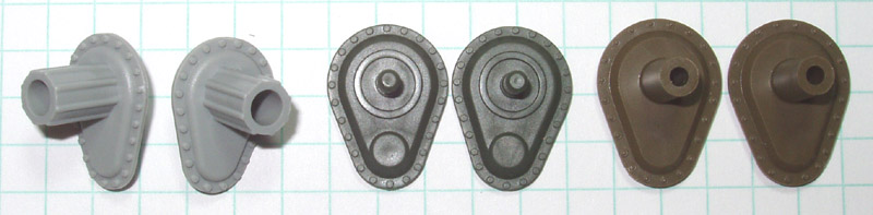
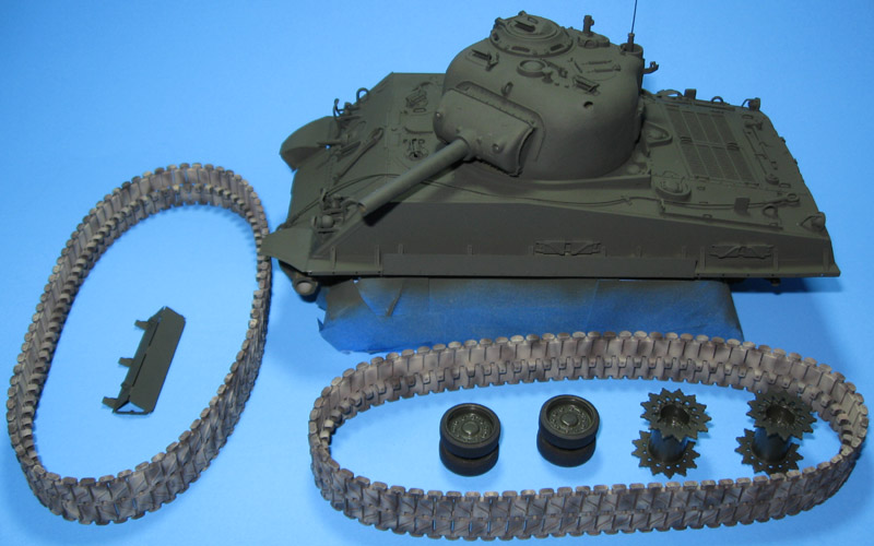
I started by dealing with the undersized final drives. The picture above shows DML, Academy, and Italeri parts for comparison. First, I sliced off all the bolts. Next, I cut very thin strips of 0.3mm plastic card and glued three layers around the edge of each drive. After that set up I sanded both sides flat and used thinned Squadron White Putty on the front to fill tiny cracks and even everything out. After another round of sanding I added cast texture to the front using Mr. Surfacer 1000. Finally, after lightly sanding the cast texture, I put back the bolts. This method does not produce a perfectly accurate final drive but, in my opinion, it looks better.
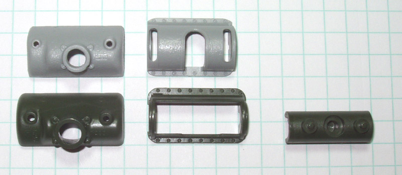
According to Terry Ashley, the kit mantlet comes in about 2.5mm too narrow. The picture above shows a comparison of M4A3(105) mantlets from DML (gray) and Academy (green).
I started correcting the DML mantlet by sawing it in three. Next, I used strips of 0.3mm card to make a brace behind the mantlet. With that dry, I added 0.3mm strip to the side of the mantlet, building it out in three layers that match the cross section of the part.
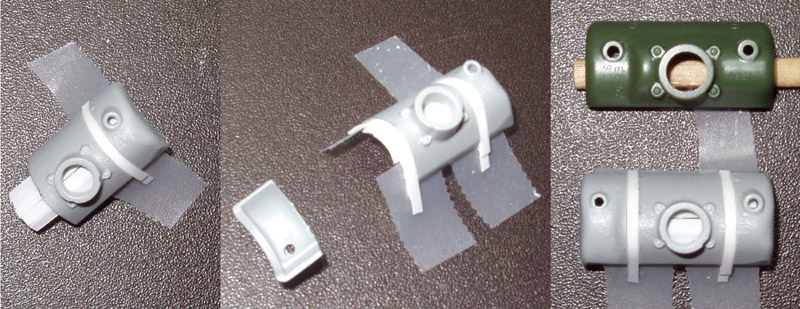
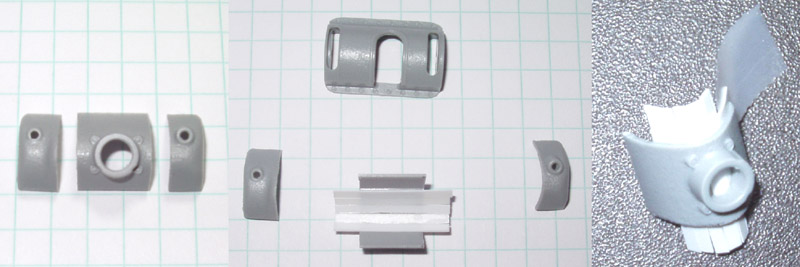
With the mantlet built out, I glued the outer piece in place. After repeating the process on the other side the mantlet matched the Academy part in width. I finished the process with some putty and sanding to even everything out. I also drilled out the hole for the main gun.
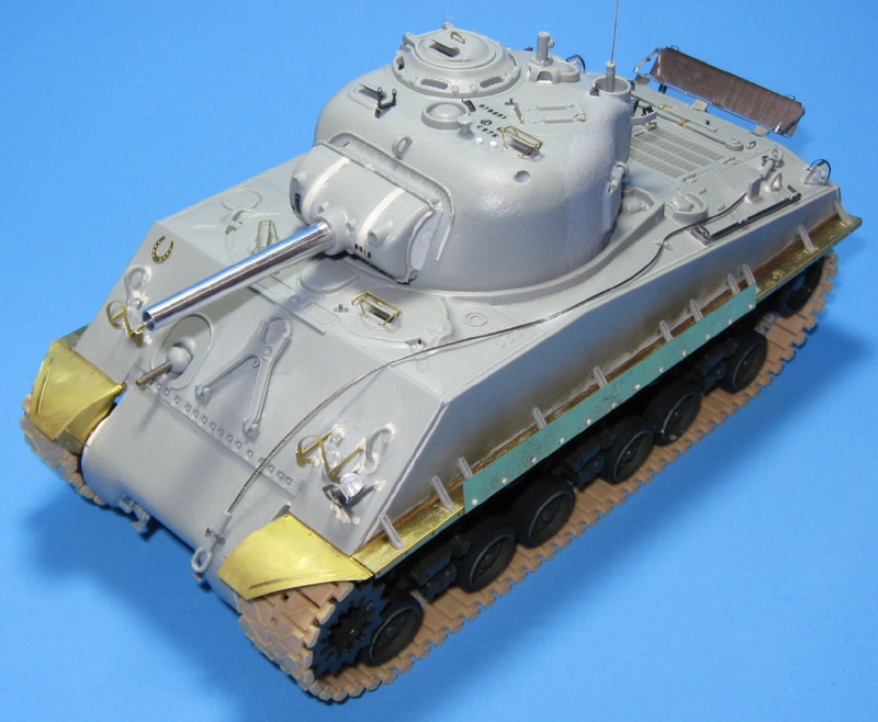
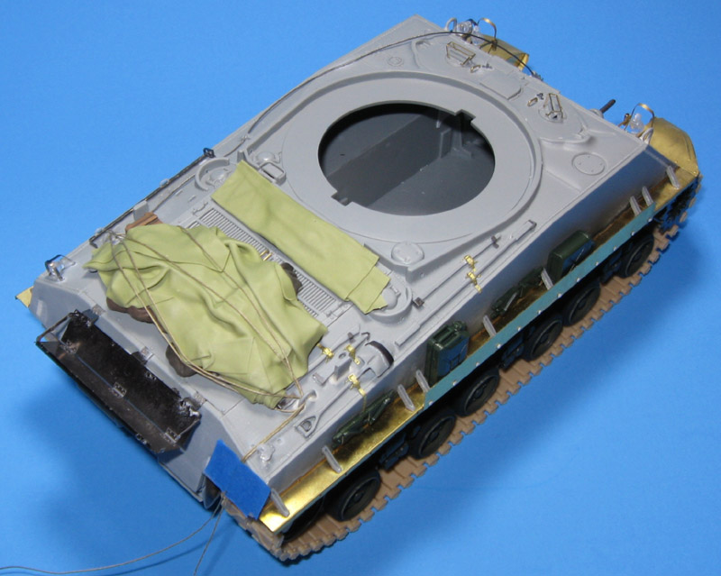
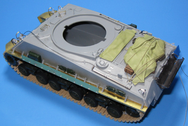
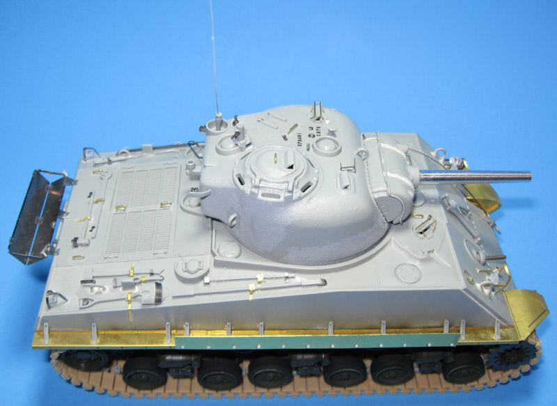
Then magic happens and I suddenly have a completed model with all the photo etch parts from an Eduard detail set in place.

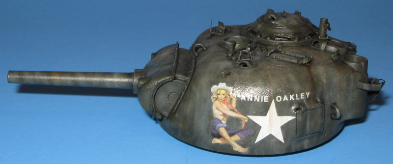
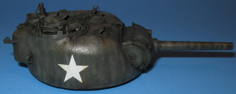
More about that mantlet: According to Terry Ashley or Perth Military Modeling the mantlet is too narrow but the rotor shield is just right. However, after building out the mantlet, the holes for the machine gun and sight no longer line up with those in the rotor shield. Also, the rotor shield just looks too narrow with that big mantlet over it. I ended up building out the rotor shield on one side to make it look better. I think something is still not right.
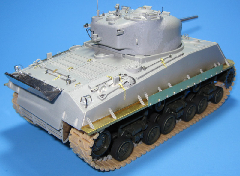
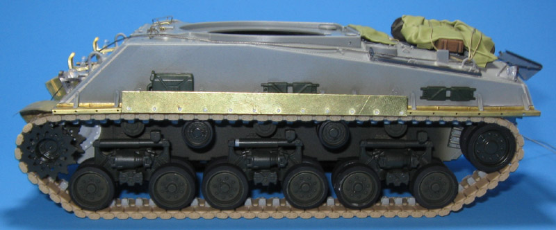
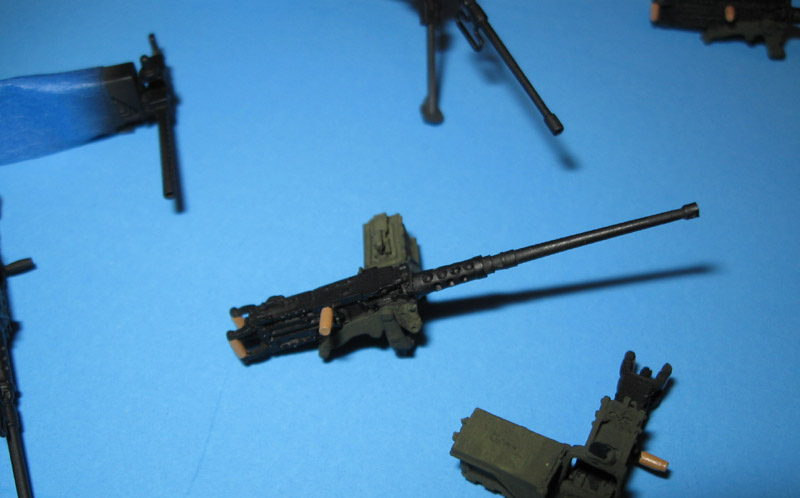
The DML HVSS suspension units have _way_ more detail than those in the Academy M4A3(105) kit. Not even close. They also require much more effort to build and align correctly.
The one piece DS tracks look _awesome_ but cleaning up and installing the guide teeth takes some modeling stamina. When I finally put the tracks on the tank I discovered two things: One, the tracks would not fit over the return rollers. I had to remove a couple guide teeth to get the tracks on. Two, my tracks are too long by 2 to 3 links! That really surprised me. Fortunately, DS tracks glue with liquid cement and stick really well so I do not anticipate trouble correcting this.
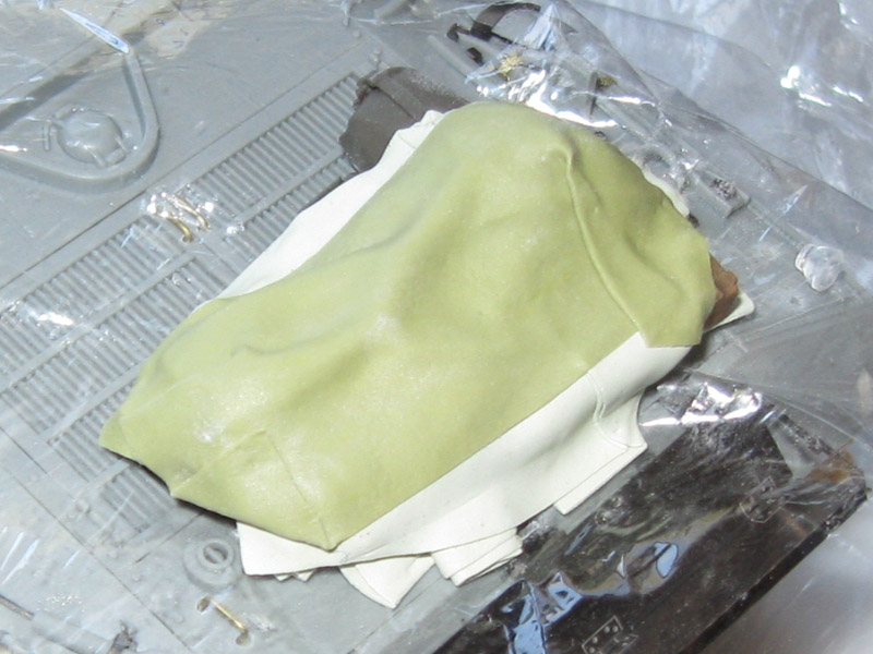
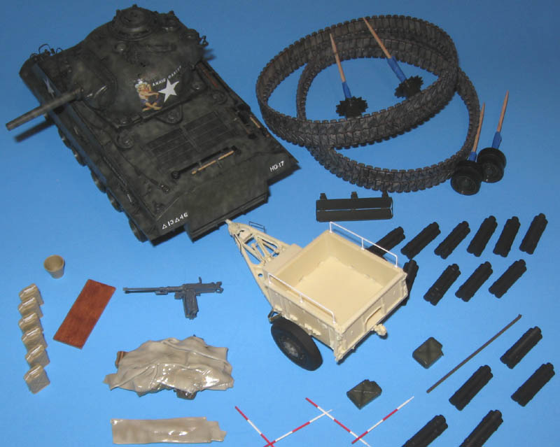
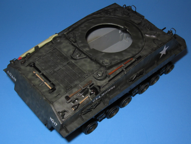
I positioned the rear shelf in the "up" position so I can paint the engine crank. With that done I will push it down and add stowage.
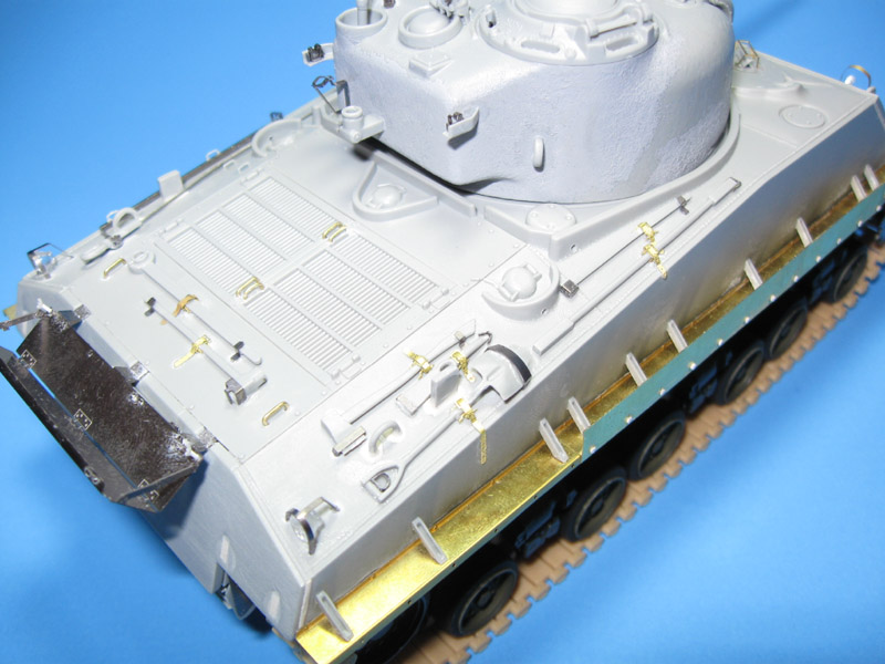
I used leftover tool belts from a Voyager photo etch set. A very well designed Eduard photo etch set provided everything else. The Eduard set includes correct parts for stowing the lower wrecking bar but I screwed them up.
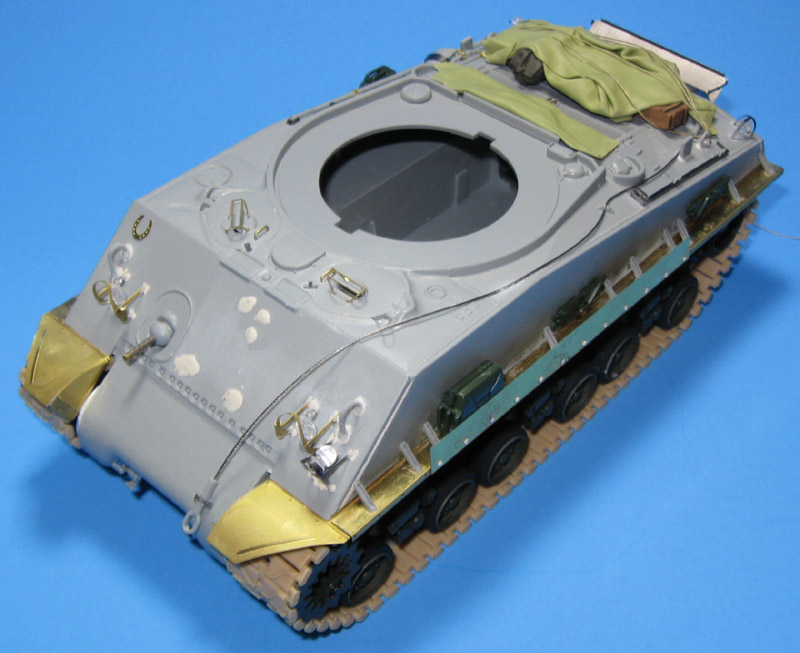
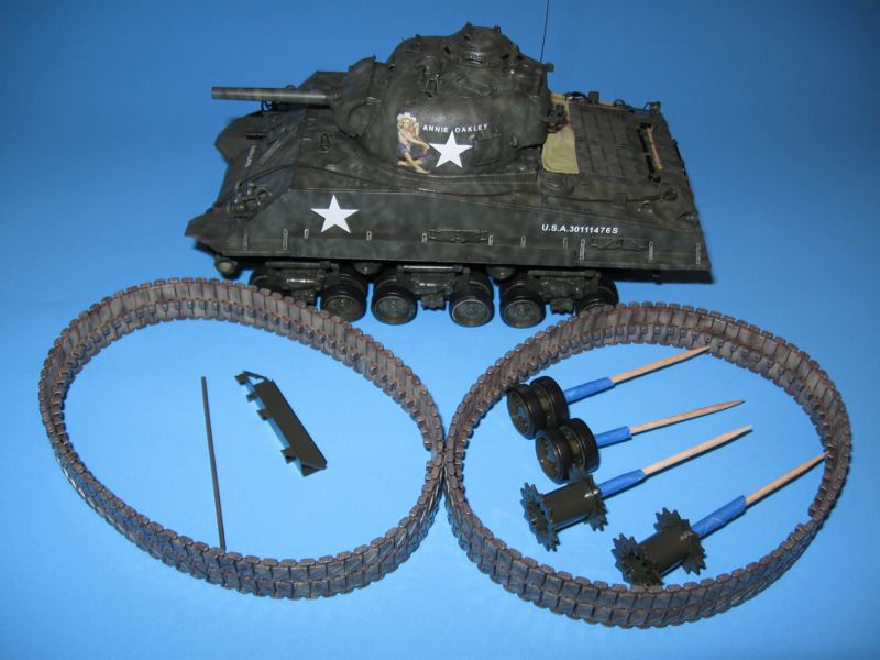
I used Archer Surface Details for the first time to make the casting marks on the turret and mantlet. I brushed on a coat of Testors Gloss Clear Acrylic to the target areas, let it dry about an hour, then applied the surface details using Microset and Microsol. They look _fantastic_. Two big thumbs up.
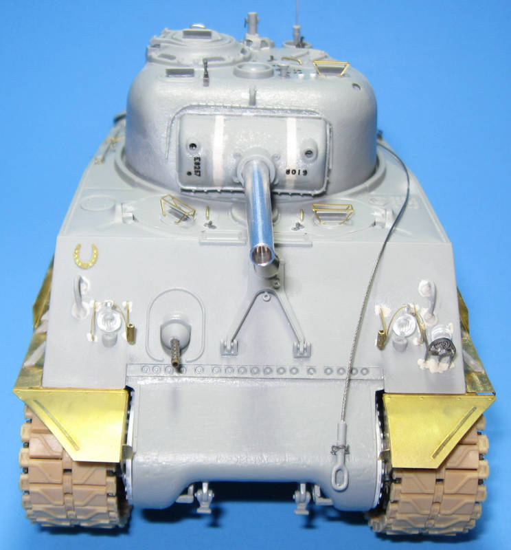
And so the project stands. I still need to sand down the welds around the brush guards, add casting marks to the transmission cover, and fix the inside face of the fenders. I'm not sure what DML was going for there. Either I built it wrong, they made it wrong, or they worked from an example I have not seen.
If I screwed anything up, please let me know. Even if I cannot fix it here, I would like to know for next time.
More next weekend.-Doug