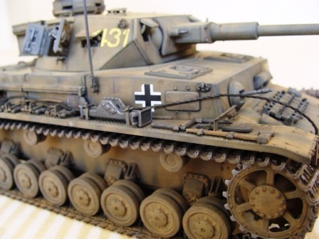
I will be putting together Dragon's 1/35th scale Pz.Kpfw.IV Ausf.F2 (G) kit #6360 for the Workhorse Campaign. I originally had another kit in mind to build for the campaign but my wife surprised me with this kit on my birthday. And after reading through Ken Schwartz's 1/35th scale Pz.Kpfw IV Ausf.F2(G) in box review. I just new I would have fun putting this kit together. And then I seen Fahri Mamedov's awesome Pz.Kpfw. IV Ausf. F2 in the Features section built straight OOTB! I also remember following Bill Plunk's excellent and informative Pz.Kpfw. IV Ausf. F2 Africa build log and wanting to run out to the LHS to purchase this kit and try out some sort of tropical scheme that Bill had featured as part of his build.
Thanks to the Workhorse Campaign (for the motivation) and my wife's thoughtfulness I'm getting the chance to build this kit and finally try out a tropical paint scheme. I don't know that I will be able to complete this build on time even with the extra allotted time frame of the campaign - due mostly to me being such a slow builder - so I've chosen to post and share my progress here with you just in case the campaign ends and I still haven't finished with this build. And because of the step by step build process that I have in mind I don't want to hog up a lot of pages with my postings in the campaign. Being my first build log I'm treading on new territory so please bear (or beer) with me. Hopefully we can all learn a little from each other and have some fun in the process.
Here are three photos and a color plate that I pulled off the internet of the vehicle that I have chosen to model . . .


. . . its of the exact tank that's rendered on the kit box cover art by Ron Volstad (nice touch with the entire village ablaze in the background) and one of the seven painting and marking options available in the kit. I couldn't find any photos of the front of this vehicle? I don't know exactly where in Russia these photographs were taken but I had read that they were taken in 1942 somewhere in southern Russia?

Nice detailed single sided color plate - gives a good idea of the colors used and how the overall vehicle was painted.
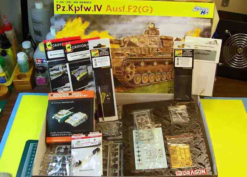
The kit and most of the aftermarket items that I will be using. Still waiting on the Modelkasten workable track links.
List of the aftermarket items:
Aber #35 L-75 German KwK.40 L/43 7.5cm metal barrel with brass single baffle muzzle brake.
Aber #35 L-63 German tank 7.92mm MG 34 (Late) brass machine gun set (will be using only one of the two barrels in the set for the turrets coaxial station).
Adlers Nest #AMN 35008 Brass 2m Antenna.
Griffon Model #L35018 German Pz.Kpfw.IV Ausf.F2(G) / Ausf.G (2 in 1) full detail photo-etch set for Dragon 6360 / 6363.
Griffon Model #L35A010 German track fenders for Pz.Kpfw.IV Ausf.F1 / F2(G) / Ausf. G accessory photo-etch set for Dragon 6315 / 6360 / 6363.
Lion Mark #LM10029 German tank 7.92mm MG 34 (Late) brass machine gun (for the R.O.'s station).
ModelKasten #MK SK-18 40cm opened horned workable track link set.
Tristar #35014 German Pz.IV Wheel Set.
VoyagerModel #PE 35141 German Pz.Kpfw.IV Ausf.F2(G) basic photo-etch set (IMHO this set compliments any of the full detail photo-etch sets currently on the market for this kit).
"But it's a Smart Kit!" I kept telling that super glue sniffing junky, plastic little devil on my shoulder. But he kept tempting me on . . . "I know, I know, but you shouldn't just build it straight Out Of The Box!" My wife still doesn't believe my story but I'm sticking to it!
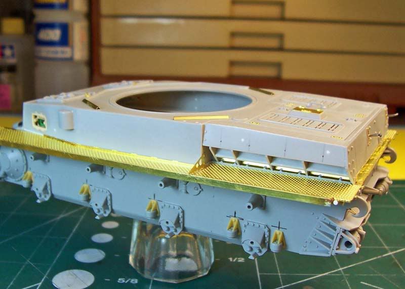
Well, here goes with this step by step, PIMP my Panzer IV, build log.
The first step I take before beginning any assembly work is not shown. This is where I use my wife's large glass baking pan filled with warm water and a little bit of dish washing soap to bath all of the parts while they are still on the sprues for about 10 minutes and lightly scrub them with a soft toothbrush to remove any mold release that may still be on the plastic. I then rinse the sprues off in cold running water . This step is very important as acrylic paints won't adhere very well or not at all to the plastic due to the mold release. I also use my wife's large colander to keep any parts that may have come off of the sprues during the washing and scrubbing process from escaping down the drain. I sometimes use her blow dryer to dry up the parts that I want to start on right after the washing but mostly I allow the parts to air dry by themselves. The other important step is dry fitting of the parts before committing them to the liquid or gooey cement monsters. I almost always build my kits from the inside out and rarely if ever follow the kits sequenced assembly instructions. I do however check out every section on the instructions and look at every part before I begin a build. So with that said I will be skipping around quite a bit during the build.

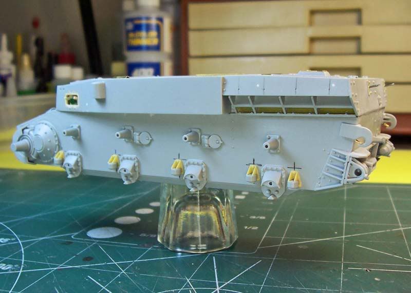
Per step 1 of the instructions I installed both forward side pieces that contain part of the final drive / differential housing flange (E8 - Right Side and E9 - Left Side) to the lower hull (Y). Followed by the [50mm / 14 deg.] bow armor plate with the [30mm / 61 deg.] lower bow armor plate (E16). And from step 5 the [20mm / 72 deg.] front glacis armor plate (E30) together with the support / alignment bar for the upper hull (E18). Except for the final drive / differential flange I filled the seams along the forward sides of the lower hull with super glue. I dampen the end of a micro brush with accelerator then place the dampened micro-brush on the plastic near the edge of the super glue. The accelerator is drawn to the super glue and within a minute your ready to start sanding. I usually slice away as much super glue while its still soft with a new X-Acto blade until almost reaching the surface of the plastic before I start sanding. The super glue is quite pliable when it first sets up and sands down very much like plastic. But the longer you wait the harder the super glue becomes getting rock hard within a couple of hours making removal difficult. Unlike many of the available filler putty's for plastic models super glue won't shrink after it completely cures. What appears to be seams on the surface where the parts are joined together in the photo is actually the transparent nature of the super glue when wet sanded to a smooth finish. By placing super glue on wax paper it won't set up and will last you through one session of modeling. I use a sewing needle or a #11 X-Acto blade as an applicator. After achieving a desirable finish on both sides I installed only the final drive / differential housing (A14) from the sub-assembly section of step 3 to both sides of the forward lower hull.

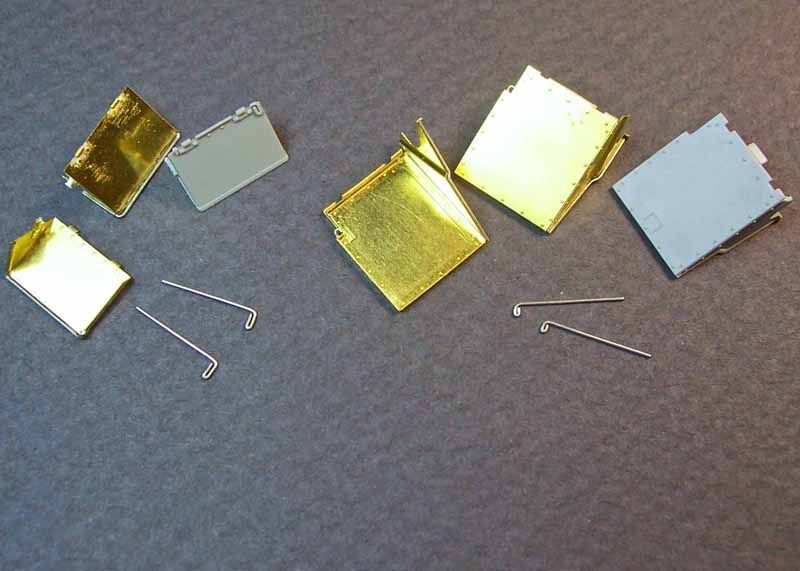
Step 5 provides you the option of installing the seven piece track links over the center of the transmission access hatch seen on some later Ausf. F2's and most early G's. I decided to forgo this option and leave the glacis armor plate without the track links so I went ahead and removed all of the lightly raised molded on placement detail for the track link support brackets. And while I was removing this I also removed the right fender stay hardware post and a few other details that will be replaced with photo-etched items. I also added the dowel pin holes on the brake access hatch hinges (this process in described below on the fuel filler hatch hinges).

This view shows the three rear pieces in step 1 of the instructions that mate up with the lower hull (Y) to produce the lower rear armor plate sections of the tank. I first removed the molded on fender, main engine and turret power traverse motor muffler support bracket that spans the upper edge of the upper vertical armor plate (E13). I had to replicate a couple of items that are molded on the bracket that were lost during removal that I will be showing you later in the build. The removed bracket will be replaced with a photo-etched replacement. A few of the rivets nearest the bracket were damaged during the removal but I was able to renew them with a little bit of super glue applied with a sewing needle. The lower vertical armor plate (E26) was then cemented together with the upper vertical armor plate almost completing the sub-assembly section of step 1 minus the engine starter crank handle port cover (E29). These two pieces make up the 20mm / 10 deg. lower hull rear vertical armor plate on the real tank. I next cemented the [14.5mm / 74 deg.] bottom angled armor plate (E11) to the bottom of the lower hull. The two upper vertical armor sub-assembled sections were then cemented to the hull rear and bottom angled armor plate.
The towing hold is not installed until step 4 where you have the choice of selecting one of three towing holds. I selected the plane towing hold (H45) without any of the hardware for the towing pintle because this is the correct piece for the vehicle I am modeling. Of the two other towing hold options one comes with hardware (H49) for attachment of the towing pintle support brackets and the other towing hold (H23) comes already fastened with the towing pintle support brackets for the towing pintle. The towing pintal itself is made up of two parts (H13 and H26). Although I won't be using these parts on my build I thought that I'd mention them to you as many of the later production F2's and almost all of the early production G's had the towing hold upgraded for using the towing pintle. I thinned down the towing hold from underneath to maintain its original height and along both sides of its two vertical support braces for a better scale thickness and to match the surrounding brackets on the vertical armor plates. I then installed the towing hold to the lower vertical armor plate with its two vertical support braces resting on the bottom angled armor plate.
Some of the location holes for mounting both the main engine and turret power traverse motor mufflers were filled with plastic rod in preparation of replacement photo-etched muffler support bracing. I used a micro-drill chucked in a pin vise to drill a hole on the lower left corner of the upper vertical armor plate for the electrical cable (not yet installed) that leads to the left rear fender mounted vehicle distance indication light and added a Verlinden Productions resin bolt head on the opposite corner (cable and bolt shown on one of my photo reference books). From step 3 are both the rear towing hooks (H57 - Left Side and H58 - Right Side) installed to their respective mount bases on opposite ends of the upper vertical armor plate (the towing hooks and mount bases are actually a single casting). And from step 4 the cold weather heat exchange water pipe (H25) near the lower center of the upper vertical armor plate. Of note; the water pipe coming out of the upper vertical armor plate is fixed parallel to the horizontal plane and not parallel with the angle of the bracket that sits just below the pipe. And also from step 4 both idler wheel mount assemblies have been installed on the right and left sides of the lower vertical armor plate.

The 10 suspension arm dampers (A13) with the suspension arm damper support brackets (W5) from the Tristar Panzer IV Wheel Set and 8 bogie wheel suspension mounts (A38 - Left Side and A39 - Right Side) from step 3 have all been installed on both sides of the lower hull. The molded on fender support brackets that span almost the full length along the outside top edge of the left and right side [30mm / 0 deg.] vertical armor plates on the lower hull have been carefully removed. Both of these fender support brackets will be replaced with photo-etched items. Not mentioned on the assembly instructions is to have you remove the 6 large molded on tabs (3 per side) that sit along the top edge of the right and left side vertical armor plates on the lower hull. You won't be able to fit the kits fenders into place without first removing these tabs.

I chucked both a sewing needle and a micro-drill into a pair of pin vises to replicate the dowel holes on the fuel filler hatch hinge bosses. The sewing needle was used to indent the plastic to help keep the micro-drill stay centered on the hinge bosses. Both appearance sides of the hinges received this treatment.

Here on the right side idler mount assembly I've sandwiched a small styrene disk between the idler shaft adjusting nuts (A25) and the two piece idler mount housing (E23 / E33 - Right Side) to produce a similar gap that I had taken note of on my photo reference book. I also added a styrene disk to the left side idler mount assembly.

By now you've probably already noticed the brass thingamajig on the towing hook so I'll explain that first. The towing hooks come molded with a small boss for the triangular shaped cable stops just like on the real ones but you'll have to fabricate your own cable stops as no one makes these pieces that I am aware? Nice touch if you happen to leave off one or both of the rear mudflaps or store them in the up position. I left just enough tension on the brass cable stops after forming them with pliers to grab the towing hook boss and applied a tiny amount of super glue with a sewing needle to set them in place. There are a couple of rectangular plates (E32 - Left Side and E31 - Right Side) from step 4 that need to be fitted against the idler mounting braces located on the rear of the lower hull. These rectangular plates together with the 5 triangular shaped mounting braces molded to the bolted on base plate, on each side of the rear lower hull, were welded together forming the idler mounting bracket on the real tank. Once the rectangular plate was set in place and the seams filled I then cemented the 3 piece idler mount (E24 / E34 - Left Side with A25) sub-assembly from step 4 into place. I repeated the same process for the right side idler mount assembly. I left off the adjusting tension handles for later. The horizontal bracket on the lower end of the the upper vertical rear armor plate extended past the idler mounting bracket on both the right and left sides on my kit. I sanded the horizontal bracket down even with the idler mounting bracket as shown on my photo reference books. I also noticed that the horizontal bracket was a bit over scale on the ends so I went ahead and thinned down both ends of the horizontal bracket to match the thickness of the plates on the mounting bracket.

Side view of the left side horizontal bracket thinned to match the plates on the mounting bracket.

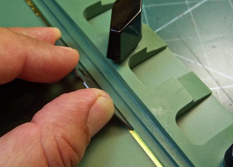
A comparison shot of the kits suspension arm damper support bracket on the left and Tristar's offering on the right. Now which ones should I go with? Hummm. . . I removed the locating pins on the backside of the suspension arm damper support brackets because they did not match up with the locating holes the hull. I marked the hull with a permanent ink marker using a small 6" scale metal ruler to help me with locating the suspension arm damper support brackets. I then test fitted one of the kit suspension arm dumper to the Tristar suspension arm dumper support bracket and found that the locating pin on the kit suspension arm damper matched up with the locating hole on the Tristar part. The locating pin on the suspension arm dumper was a little long so I trimmed it flush to the Tristar part. After assembling all 10 suspension arm dumpers to the suspension arm dumper support brackets I cemented the completed sub-assemblies from step 3 to the lower hull.

Here you can see that the Tristar bogie wheel suspension mount housing is a tiny bit larger than the kit part. I decided to go with the kits bogie wheel suspension mount housings.

Although I won't be using the Tristar bogie wheel suspension mount caps I thought I'd share them here with you. They won't fit onto the kits bogie wheel mounts - you can see that they're just a bit larger in diameter that the kit pieces.
I may or may not be using some of the Tristar working suspension components as the kit comes supplied with a non working bogie wheel suspension and I wanted to have the option of a working suspension? Anyhow, here's what I had to do to adopt some of the Tristar working suspension parts to the Dragon kit in the event I do decide to use the working suspension?

I assembled 8 of the Tristar 3 piece quarter elliptic leaf spring suspension arms (s1-14 / s1-15 - Left Side with s1-11 and s1-22 / 1s-23 - Right Side with s1-11). I had thought to use the kits suspension arm end piece (A48) but the Tristar's hollowed out end piece(s1-11) matched my photo reference book. The end piece is actually a part of the casting on the quarter elliptic leaf spring suspension arm. The horizontal bars on the end piece represent the encased leaf springs. As a note the Tristar instructions have s1-15 as a right side part and s1-23 as a left side part, this is incorrect. At the same time I went ahead and assembled the corresponding 8 floating suspension arms (1s-12 / 1s13 - Left Side and 1s-20 / 1s-21 - Right Side).
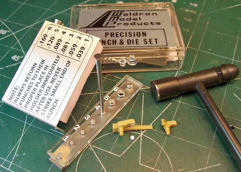
To be able to adapt the Tristar workable suspension to this kit I first had to bring down the inside peg hole diameter on the bogie wheel axle side of the assembled leaf spring suspension arms. The peg hole is to large in diameter for the peg on the kit suspension mount caps (A44 - Right Side and A45 - Left Side). I drilled out the holes on each of the leaf spring suspension arms to accommodate a styrene disk that I made from the #4 punch of the Waldron Punch & Die set.

After installing a styrene disk to each of the leaf spring suspension arms I drilled a hole in the center of the disk to accommodate the corresponding peg on the suspension mount cap. No modification was required on the bogie wheel axle side of the floating suspension arms.

On the bogie wheel housing mount side of both the leaf spring suspension arms and floating suspension arms I placed a styrene disk centered over the peg holes and drilled a hole in the center of the disk to accommodate the suspension mount housing pegs. The #3 punch was used for the disks on the floating suspension arms and the #4 punch for the disks on the leaf spring suspension arms.

There are two different diameter size pegs on the suspension mount cap that correspond with the pegs on the suspension mount housing to assist you with assembling the bogie suspension ensemble and keep it correctly orientated.

With the bogie wheel leaf spring suspension in the raised position.

And in the lowered position.
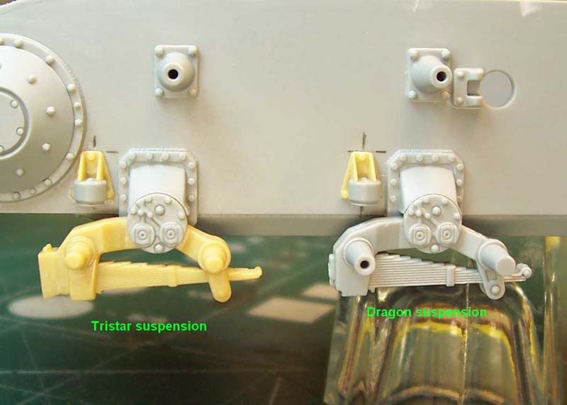
A comparison photo of the assembled Tristar workable bogie wheel suspension on the left and the kits non-working suspension on the right minus the end piece. Note the extra number of leaf springs on the kits suspension and the crisper detail.

An overhead view of the the bogie wheel suspension. The kits suspension arms are wider than the Tristar parts.

Bottom view of both the Tristar and kit bogie wheel leaf spring suspension assembly with the styrene disks on the housing mount side of the thinner Tristar suspension arms. The kits suspension parts better represent the robustness of the later designed suspension components to handle the higher overall weight of the heavier Panzer IV Ausf. F1 through G series of tanks. The Tristar suspension parts are better suited for the earlier series of Panzer IV tanks. At this point I have only test fitted the suspension components to the chassis for the photos and for anyone wishing to use the Tristar Panzer IV wheel set on their build using this kit. As you can see its workable! Now I'll have to decide weather to use the more accurate kit non-working suspension parts or the (you won't know the difference once the wheels are mounted) workable Tristar parts?

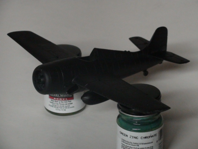
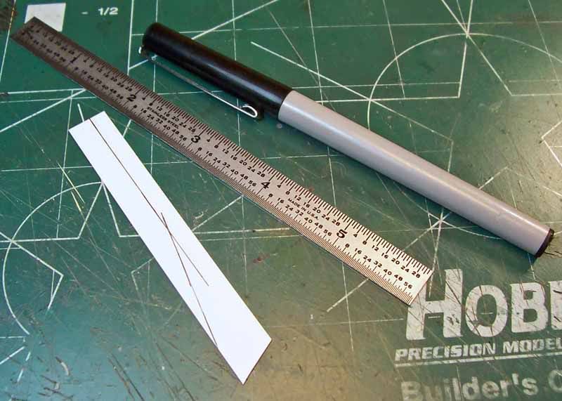
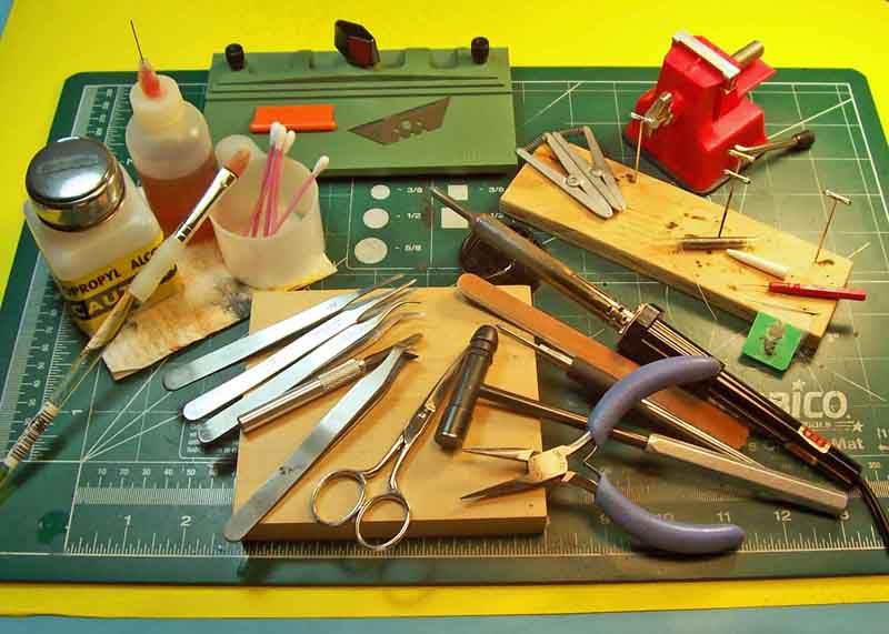
These are the tools, adhesives and finishing items that I used during this first installment of my build.
Any comments are welcome, thanks for stopping by and having a look - more coming soon!
-Eddy