_GOTOBOTTOM
Armor/AFV: Braille Scale
1/72 and 1/76 Scale Armor and AFVs.
Hosted by Darren Baker
Roden SdKfz4 8cmRaketen-Vielfachwerfer build
firstcircle
Visit this Community
England - South East, United Kingdom
Joined: November 19, 2008
KitMaker: 2,249 posts
Armorama: 2,007 posts
Posted: Monday, April 23, 2012 - 10:22 AM UTC
After the example set by an award winning modeller and fellow braille reviewer, some may have noticed my partial build review of this:

The review can be accessed here.

For the review I built the launcher assembly only and just demonstrated it dry fitted on the body. Now for the rest of the model, from the beginning.

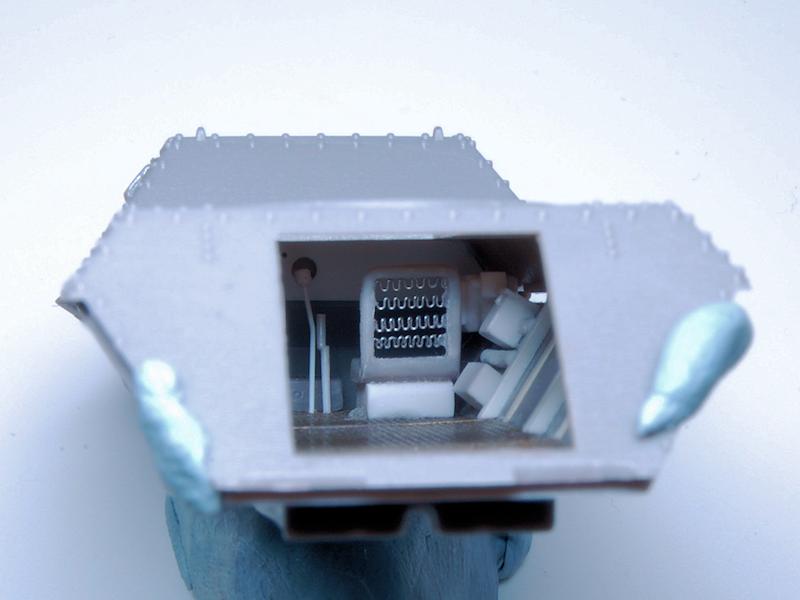
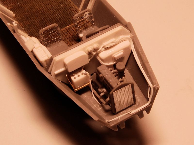
Step 1 starts out with the engine casing in two halves with a wacking great chunk of styrene on each, which I snapped off with pliers:


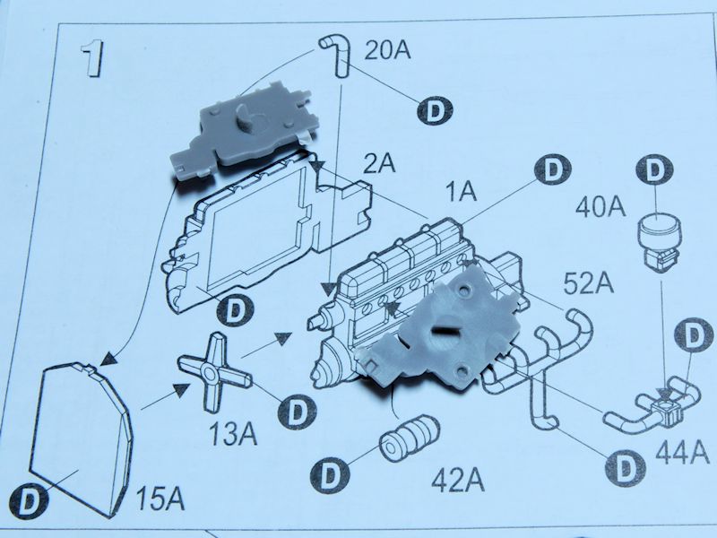
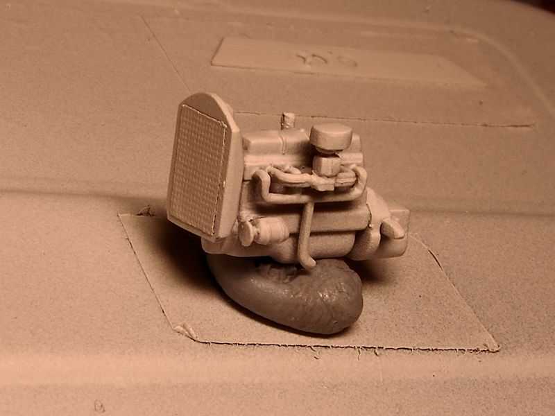
The separate fan was a bit of an odd shape in that the blades weren't at 90deg to each other, but it ends up inserted into a circular recess in the radiator (15A) anyway. That had a big ejector hole in it which I removed by lots of sanding with the glass nail file (my current favourite tool). End of step 1 is below. That's the distributor cap and the ignition coil lying just in front of the engine.


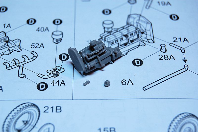
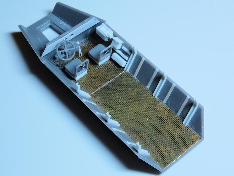
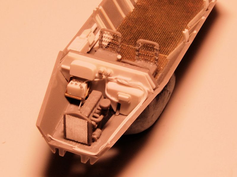
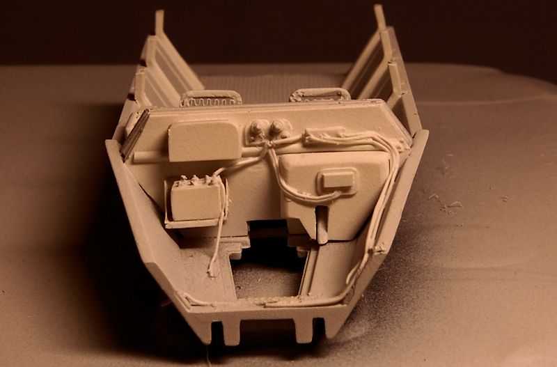
Step 2 takes us to this:


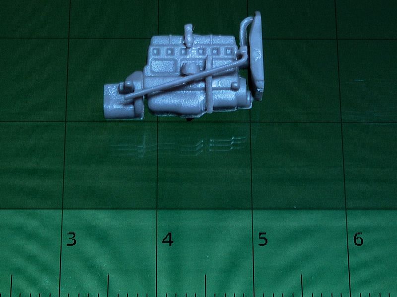
In the second photo above I don't know if that pipe/hose thing that comes out from behind the radiator is meant to be at that angle, but it's one of those slightly frustrating things where you never get a drawing of the item completed in the instructions, except for from the opposite side. I'm guessing it's meant to exit through the floor somewhere though. So the engine will get a little clean up when it is all set, and possibly a bit more detailing, prior to painting.

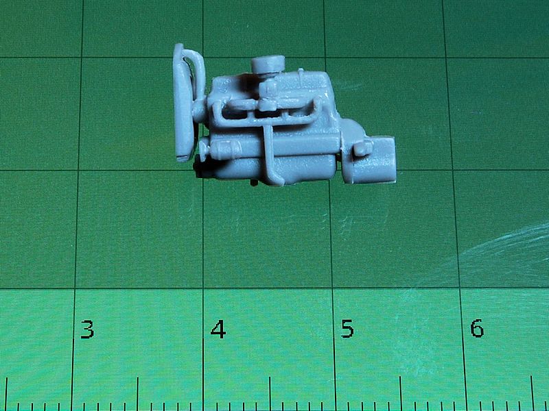
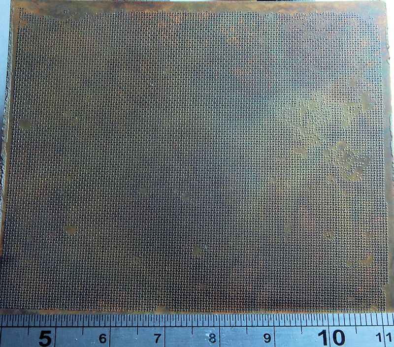
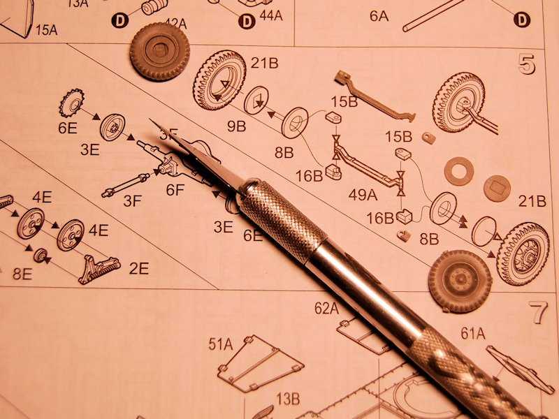
For those that like 1/35 scale models, you can pretend those increments are inches. For the rest of us, they're centimetres. I didn't have any Canadian coins handy.

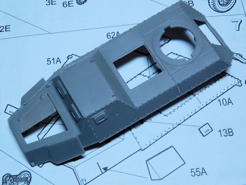
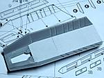
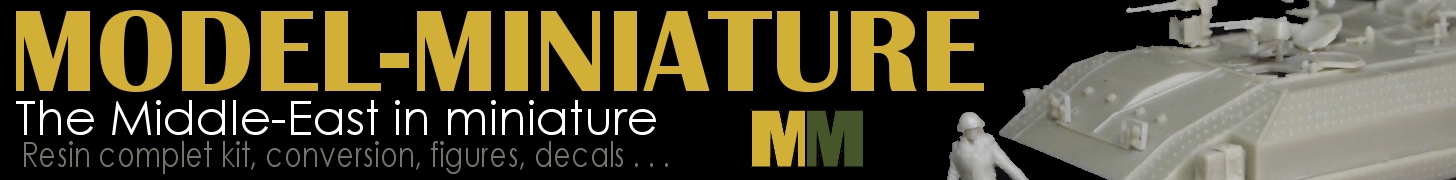
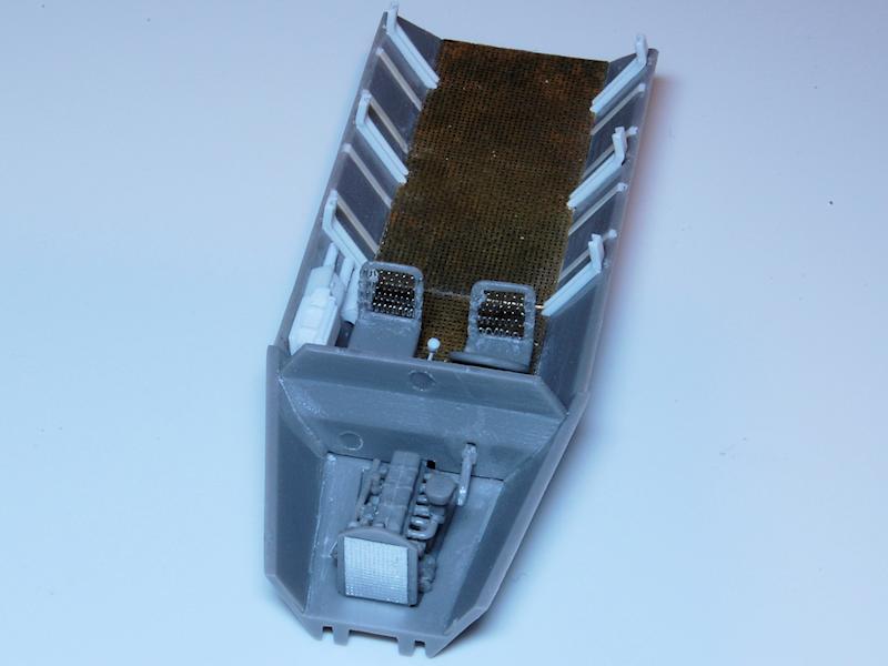
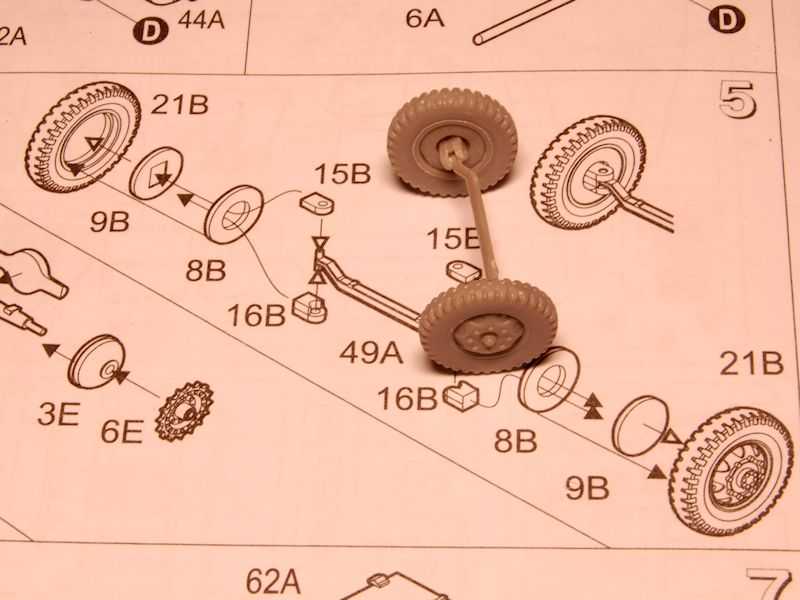
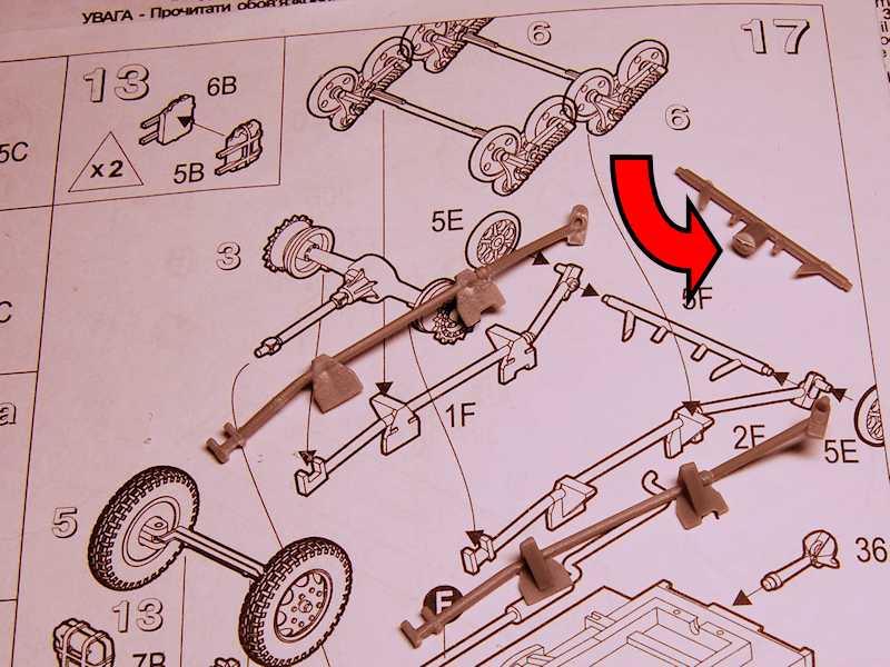
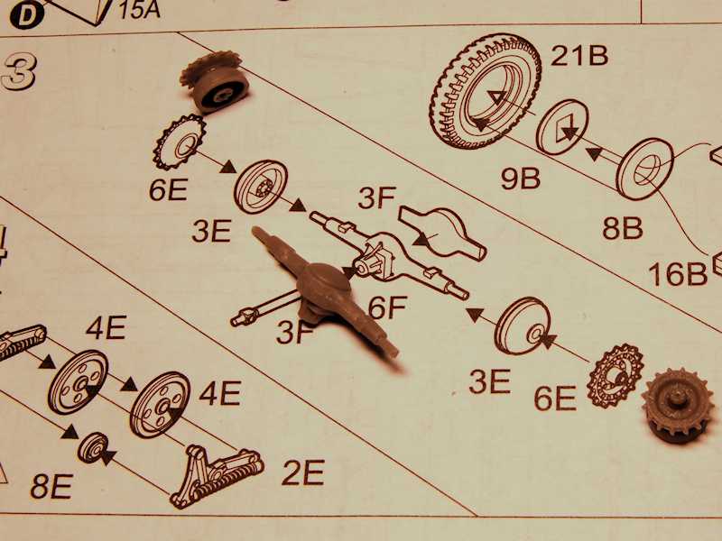
For now I skipped over steps 3 to 6 which is wheels and suspension as I'd had enough of really tiny fiddly pieces for a long Friday evening, and moved straight to the upper bodywork in step 7 with its relatively big pieces.

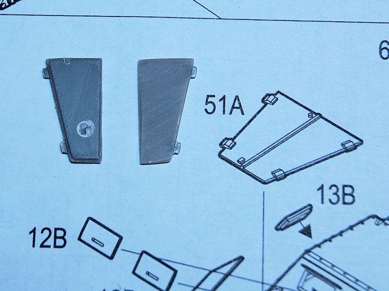
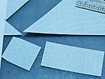
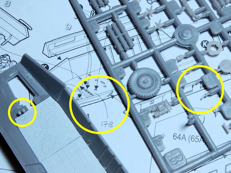
As mentioned in the review, the various doors are all separate from the body, but joined together in pairs, so to show them open we need to cut them in half, thin them down and eventually add some details to the insides where necessary. So this is the bonnet (hood) doors separated, with the right hand one most of the way to being filed down with the glass file; I suppose some might prefer to simply re-fabricate these doors out of thinner styrene sheet or brass, the shapes are all very simple.

Left hand one shows the ejector pit and the chamfered edge:


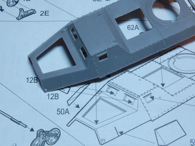
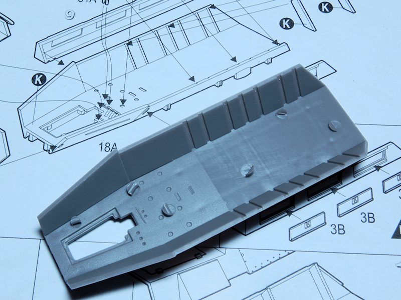
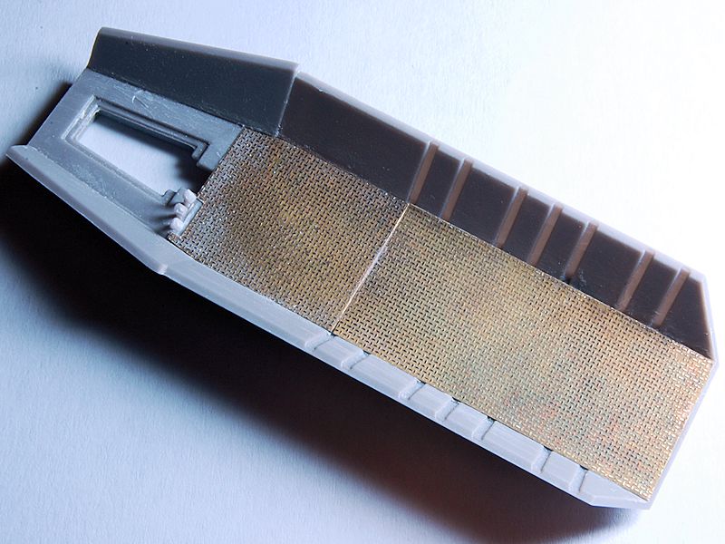
Similarly the chamfered edge of the engine compartment opening was removed and the sides thinned down:


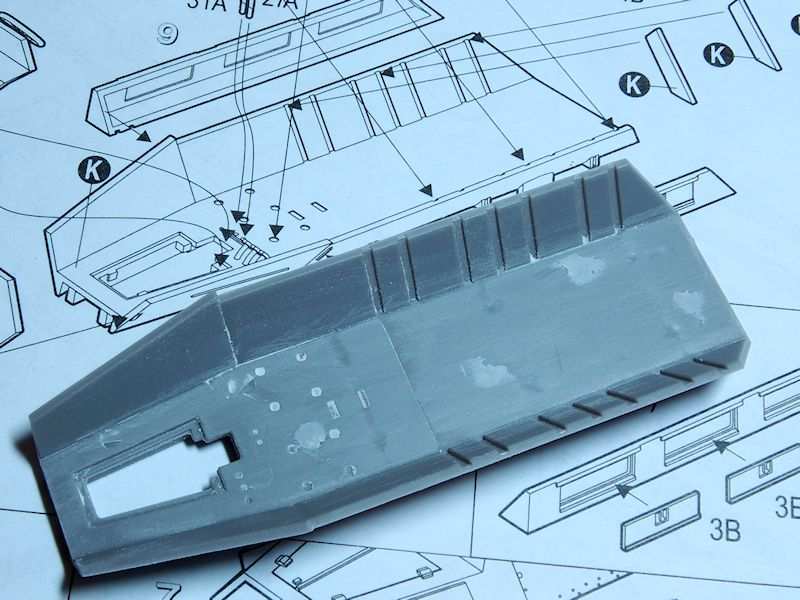
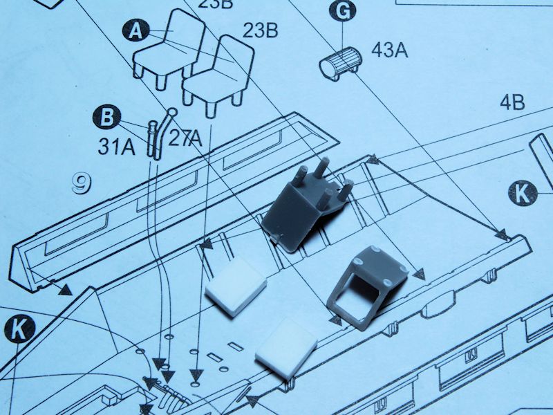
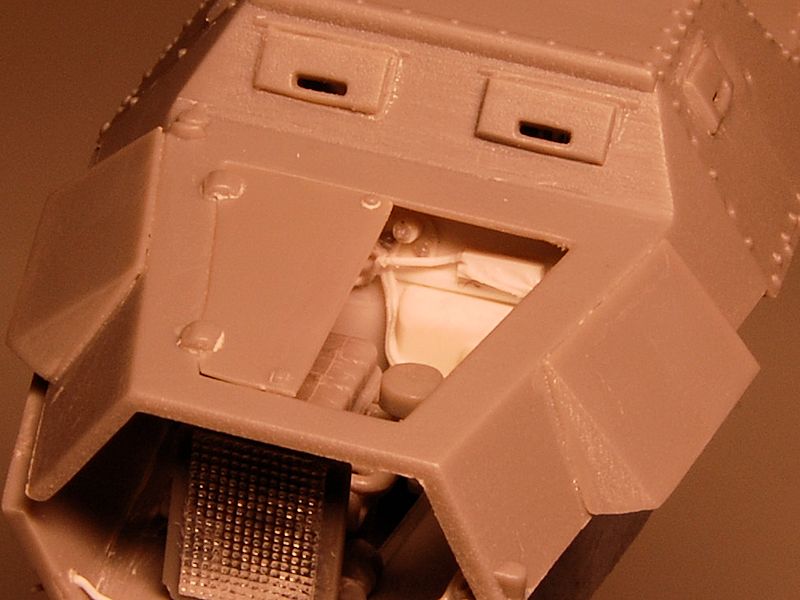
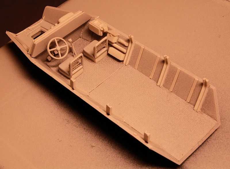
And finally for now, the same halving and thinning process is started with the doors in the top of the superstructure; top one is already nice and thin:


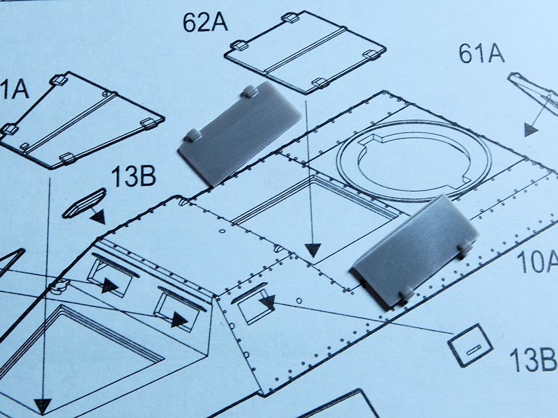
The interior detailing that was provided for the 15cm rocket launcher doesn't apply to this version, although the parts are all present, as that was largely racks for the bigger rockets. In this model they have left that part of the interior largely bare, presumably as there is no evidence of what it looked like. I will have to improvise in order to show these roof doors open, but I have some ideas. If anyone else has thoughts on it, please feel free to share...
russamotto
Visit this Community
Utah, United States
Joined: December 14, 2007
KitMaker: 3,389 posts
Armorama: 2,054 posts
Posted: Monday, April 23, 2012 - 04:01 PM UTC
Looks good, Matthew. Nice and clean. I don't blame you skipping the suspension for now. Lots of fiddly bits. Check the width of the drive sprockets against the idlers at the rear. The drive sprockets are narrower and will create some fit issues with the tracks. I left mine closed up, but I would guess that the rear compartment was very similar, only carrying more rockets.
tread_geek
Visit this Community
Ontario, Canada
Joined: March 23, 2008
KitMaker: 2,847 posts
Armorama: 2,667 posts
Posted: Tuesday, April 24, 2012 - 03:30 AM UTC
Matthew - Nice to see this Blog about this vehicle bring presented to this community. If one would like to have one of these unique critters in their collection then for the time being this Roden kit will be the only option, despite its issues (or perhaps order one of you hand built reproductions made during the Braille Battlefield campaign). I'll be following this build just in case one of these kits happen to materialize at a local retailer.

As for your remark about not having having a "Canadian coin" handy. The coin in question is a one cent piece and is equivalent in size to its U.S. counterpart with a diameter of .75" (≅19 mm). Perhaps there is a UK coin of equivalent size or in a pinch I could mail you one of each of the North American standard.

Your use of the the kit instructions as a background for the parts is most innovative and effective.

Cheers,
Jan
firstcircle
Visit this Community
England - South East, United Kingdom
Joined: November 19, 2008
KitMaker: 2,249 posts
Armorama: 2,007 posts
Posted: Saturday, April 28, 2012 - 11:11 AM UTC

Quoted Text

The coin in question is a one cent piece and is equivalent in size to its U.S. counterpart with a diameter of .75" (≅19 mm). Perhaps there is a UK coin of equivalent size


Jan, well, there is the one pence piece, but that's a precise metric 20mm diameter, so I thought it might be misleading...

An update on recent activity: here is the upper body with the addition of one of the bonnet doors, the engine ventilator armour plates and the vision port visors. The vision port visors are separate pieces, but to be able to show them open, you'd really need to do some work on their inside surfaces, as I'm sure these weren't just thin pieces of armour plate, I think they contained glass blocks. Mine are glued shut.


Putting that aside to dry, here's the lower hull with some big lumps of plastic sticking out of the floor; twisted these off with pliers, then filed down (glass nail file again) and filled in the indentations.


Now an experiment, not sure if this will work. The floor needs to have a treadplate pattern on it, not sure if you can buy 1/72 scale styrene sheet like this, though no doubt you can get etched metal. I was considering etching my own, the process for which would start with drawing up the pattern on the PC. Start with a squashed hexagon vector, then copy it, turn it 90degrees and space it along from the first, then copy and paste those, and so on until you get this kind of thing:


and then after pasting that out several times on to a bigger layout, this: (you might need these: )


I was already thinking about how deep the texture would have to be in 1/72 scale, and that in reality the tread pattern is perhaps no more than 1 - 2mm deep, and of course I'm only looking for an appearance of this through a couple of open doors. So before putting myself through the whole process of transferring the pattern to brass sheet and standing in the garage mixing chemicals, I thought I'd just see if I can get enough texture from the toner printed on the paper.

I "guesstimated" how small the pattern should be then printed two squares big enough to cut the flooring from - one with normal amounts of toner, the other with heavier toner, then sprayed these with several coats of white primer; as can be seen the pattern remains visible since it is quite hard covering over black on white with white paint. I'm hoping the paint will toughen up the surface a little while still keeping some of the pattern. Edit: this really didn't work, so I reduced the photo to a thumb...


Here's two sheets of flooring, the rear section piece with the pattern at 90deg, the driver section with it at 45deg; I took this detail from some photos I found of the interior of such a vehicle, though this isn't the same as I have seen it represented elsewhere.


And now glued in place with enough styrene cement to ensure the whole of each sheet is firmly attached. If this doesn't work when it comes to painting the interior, I do have a back up...It didn't.
[

The driver's foot pedals appear in the instructions, and there are four pedals provided (two part 17s on each of the two B sprues) but for some reason the step of attaching them isn't shown, they're just shown already in place! Photo below shows two pedals attached, two on the sprue.


Putting that aside for the wobbly pedals to set, now on to the seats. These seem a bit like seats that were designed just out of someone's imagination about what a seat is like, rather than being based on any real seat, so there's a cushion, a back reast and four legs. In reality it seems the seats were mounted on kind of plinths, so I pulled the legs off, sanded the stumps, then started removing most of the backrest: drill holes in each corner, cut between the holes then carved and filed down. The seat backs were actually tubular steel frames with wire sprung support and a pad against that. I'm trying to think of a way of representing the wire backs, attempts so far haven't really looked good. I'm not bothered about the seat base cushions as they won't be very visible through the back doors in the way that the seat backs will be. The two white blocks from thick styrene card are the seat plinths.


PantherF
Visit this Community
Indiana, United States
Joined: June 10, 2005
KitMaker: 6,188 posts
Armorama: 5,960 posts
Posted: Saturday, April 28, 2012 - 11:34 AM UTC
Nooooooo! No matter what scale, I just luv this AFV!! Again, another one slipping by under the radar.

Very nice!


~ Jeff
tread_geek
Visit this Community
Ontario, Canada
Joined: March 23, 2008
KitMaker: 2,847 posts
Armorama: 2,667 posts
Posted: Sunday, April 29, 2012 - 03:41 AM UTC
Matthew,

Very nice to see work continuing on this beast. Brfore I comment further on this instalment, I got a response from a colleague that is quite the expert on Soviet equipment (and has a library to match) pertaining to your earlier question about how the 82mm rockets were stored and shipped. According to him:


Quoted Text

I've only seen a couple of photos of how they've been shipped due to NKVD controlling the launchers. I have only seen wooden crates been used to transport the rockets. It looks like they were packed in 2s or 6s usually hauled in the back of a truck 80-100+ feet away from the launch vehicles. But it was Soviet practise to shoot the rockets then move to a new location to avoid counter battery. So i'm not sure how the Germans did it but the soviet launchers always travelled preloaded because of the lengthy reload time. Hopefully some of this is helpful.


He later offered that reload time for the 24 rail launcher was on average 50 minutes. Also, the average rocket weight was 15-16 pounds so extrapolating from that, a full reload would weigh 360 LBs. Then you might consider the space taken up by the boxes to guesstimate the number of reloads that might fit in the interior.

As for the vision ports, they were just plain formed pieces of armour plate. Internally the ports had a thick glass "window" that was hinged at the bottom and folded down into the interior. The same applied to the 251 version and you can see an image of them HERE. Also, the Dragon half-tracks in 1/72 have a similar arrangement.


As for tread plate, do you have a local model train shop that you could visit? I checked at one in my area and they had three different patterned plates in PE and HO (1/87) scale. I'd imagine that would be close enough to suit you purposes.

Cheers,
Jan
firstcircle
Visit this Community
England - South East, United Kingdom
Joined: November 19, 2008
KitMaker: 2,249 posts
Armorama: 2,007 posts
Posted: Sunday, April 29, 2012 - 10:00 AM UTC
Jan, thanks for the info on the rocket storage, it backs up what I had been speculating over, which is that while the 15cm rockets were stored in tubes held in racks, it makes sense that a larger number of smaller 8cm rockets would be more likely to be packed in crates. Now I'm building this it has also become very apparent just how little space there is in the back of these vehicles. I'm thinking therefore that it will essentially be left empty-ish, with just the seat and controls for the launcher.

I can tell that you have little faith in my printed treadplate... and after painting a sample, I'm not sure the experiment has been a success. The pattern is a little too subtle, shall we say. While pondering that I came up with something for the seat backs anyway, which is wire unwound from a guitar string, then crushed flat into a zig zag pattern which hopefully resembles somewhat the loopy sprung wires of the real seat backs. Trying to obtain loops at the end of each zag proved far too hard to get small or even enough, so this will have to do. Left hand one looks much neater than right, for sure.


r2d2
Visit this Community
England - South East, United Kingdom
Joined: April 13, 2006
KitMaker: 424 posts
Armorama: 419 posts
Posted: Monday, April 30, 2012 - 02:45 AM UTC
Crackin' stuff! got to love those seats!
firstcircle
Visit this Community
England - South East, United Kingdom
Joined: November 19, 2008
KitMaker: 2,249 posts
Armorama: 2,007 posts
Posted: Monday, April 30, 2012 - 10:34 AM UTC
OK, after the failure of my lazy attempted shortcut with printing the treadplate, I had a look at a few offerings on the web, but was disappointed in terms of the only small scale stuff I could find was diamond pattern (not really right) or, if the right pattern, it was 1/35. One site sold nine types of vac-formed sheet, all listed as "Styrene VAC Formed Treadplate" - no indication as to the pattern or size. Erm...hmmm.

Rather than wasting time wondering, I got out the press'n'peel and laser printed a square of it with the same pattern, which was then ironed on to a thin brass square. From the garage shelf came the toxic ice cream tub with last year's etchant in it, now an evil brown/black sludge. I use the bag-in-bag method, so the etchant is in a small zip lock bag, contained in a bigger zip lock bag. It was heated up by pouring hot water into the tub and leaving the bags in it for a few minutes. Then the brass was put in, the bags sealed up and five minutes of running back and forth over the bag with a fluffy mini paint roller was enough to get some texture on the sheet. After a slight clean up this rather imperfect but sufficiently decent treadplate was revealed.


weathering_one
Visit this Community
Ontario, Canada
Joined: April 04, 2009
KitMaker: 458 posts
Armorama: 456 posts
Posted: Tuesday, May 01, 2012 - 07:57 AM UTC
A very high quality informative review. My thanks to people like you for making the effort and time to provide us with information. The kit looks like it has a few problems with it but I'll be following this build.

Regards,
AJ
firstcircle
Visit this Community
England - South East, United Kingdom
Joined: November 19, 2008
KitMaker: 2,249 posts
Armorama: 2,007 posts
Posted: Thursday, May 03, 2012 - 11:02 AM UTC
Thanks very much AJ, your feedback is appreciated, although the effort is also enjoyable.

This evening the floor fitters have been in and we have a new brassy grippy two part floor:

weathering_one
Visit this Community
Ontario, Canada
Joined: April 04, 2009
KitMaker: 458 posts
Armorama: 456 posts
Posted: Friday, May 04, 2012 - 12:46 PM UTC
Your alchemy is beyond me but I have to say the results speak for themslves. Some of you guys I swear have a streak of modellers OCD.

Regards,
AJ
r2d2
Visit this Community
England - South East, United Kingdom
Joined: April 13, 2006
KitMaker: 424 posts
Armorama: 419 posts
Posted: Friday, May 04, 2012 - 11:33 PM UTC
Fantastic Matthew! I loved the way the anti skid looks with areas of wear and tear which makes it looks more convincing.
newfish
Visit this Community
England - West Midlands, United Kingdom
Joined: June 23, 2008
KitMaker: 2,329 posts
Armorama: 2,110 posts
Posted: Sunday, May 06, 2012 - 05:49 AM UTC
HI Matt. I like the start you've made on this interesting half track variant....One thing regarding the tread plate though for future reference a company called Slators Plastikard make treat plate in various scales designed for 1/72 and smaller they do larger ones aswell I think Great start I look forward to this coming on more...

Jaymes

tread_geek
Visit this Community
Ontario, Canada
Joined: March 23, 2008
KitMaker: 2,847 posts
Armorama: 2,667 posts
Posted: Sunday, May 06, 2012 - 06:20 AM UTC
Looks fabulous Matthew! I can appreciate that you probably had time constraints to consider when I made the suggestion about trying to find something similar in a train shop but I went back to the shop where I saw the samples and they are by JTT Plastic Patterns and a description of what I thought would be suitable can be found at This Link." A search also showed that Archer Transfers also has a similar product but at nearly three times the cost of the JTT ($6.00 for two sheets).

Cheers,
Jan
firstcircle
Visit this Community
England - South East, United Kingdom
Joined: November 19, 2008
KitMaker: 2,249 posts
Armorama: 2,007 posts
Posted: Monday, May 07, 2012 - 10:49 AM UTC
James and Jan, thanks for the pointers on the treadplate. The JTT stuff looks almost as good as mine . The Slaters sheet is I think what I found on that site where it didn't state which item was which, so I couldn't work out which one of the several item numbers to order - I can't figure out how anyone does business like that! No doubt there are other suppliers however. Already having some of the press'n'peel sheets and some of the etchant mixed already, plus a spare piece of thin brass meant that it didn't really cost anything other than a bit of time - and I only needed a tiny bit.

Val, I'm still wondering whether to try to carry that "natural" wear look through or not - I was originally going to paint it over, and in real life it doesn't look quite as nice as in the photo actually. That finish is caused by the combination of the masking material (on the raised pattern) and the ferric chloride staining.

Have pretty much finished the detailing of the lower part of the crew and stowage compartment. I used a combination of a photo of the Verlinden 1/35 detail set and some interior shots of a real vehicle from the web. Both references were the 15cm rocket version, so as Jan referred to previously, the stowage for the 8cm version more likely involved the rockets being packed in boxes rather than in individual cases and racks. The kit has items that stick out like the 15cm racks but without the circular cut outs into which the rocket cases presumably sat. I ignored these and instead added channel section vertical reinforcement beams, as suggested in the photo of the real thing, where they were visible in between the racks. The other vertical indentations were filled with strip. The reinforcing beams are bent over to accept the upper hull.


As can be seen, the seats are in, and there's a radio, some, erm, other bits and bobs next to it, gear lever and hand brake and a dashboard, a little of all of which should be visible through the open back doors and open roof hatch.


Next will add some detail to the engine compartment, as some of this will be shown through a single open engine cover. Started with a piece of embossed foil from a fancy chocolate bar to give the radiator some texture. The top part of the bulkhead needs to be built out so it is almost in line with the opening rather than set 3mm or so back.

r2d2
Visit this Community
England - South East, United Kingdom
Joined: April 13, 2006
KitMaker: 424 posts
Armorama: 419 posts
Posted: Tuesday, May 08, 2012 - 06:55 AM UTC
The anti skids look mighty fine to me Matthew. Details you added is bringing it to life.

Cheers!

val
SDavies
Visit this Community
England - South East, United Kingdom
Joined: January 09, 2010
KitMaker: 979 posts
Armorama: 959 posts
Posted: Tuesday, May 08, 2012 - 07:10 AM UTC
Wow very impressive work, looking great so far

S
newfish
Visit this Community
England - West Midlands, United Kingdom
Joined: June 23, 2008
KitMaker: 2,329 posts
Armorama: 2,110 posts
Posted: Tuesday, May 08, 2012 - 08:52 AM UTC
Their website isn't the best. Work stock it so if you need some or a link i'll provide it for you ? Great work on the interior it looks realy smart! I am looking forward to see how you tackle the paint on the interior...

Jaymes.

firstcircle
Visit this Community
England - South East, United Kingdom
Joined: November 19, 2008
KitMaker: 2,249 posts
Armorama: 2,007 posts
Posted: Sunday, May 13, 2012 - 05:21 AM UTC
Thanks all for the good feedback. As noted before, to detail the engine compartment, the bulkhead separating the engine from the cab needs to be built out so that it doesn't sit so far back from the opening. Having already made a new dashboard using the kit dash as a template, that in turn was used to template the top of the bulkhead thickener, which was two layers of 2mm styrene followed by a 1mm layer, applied at a slight angle to so that it sloped out to the bottom, rather than being completely vertical.

Two more areas were built out even further, on the left is, I believe, the storage compartment on the passenger side, and on the right is the space which accommodates the foot pedals and other controls from the cab.

Then some electrical bits and pieces were added. I think that's the wiring from the controls / dash that comes through in the upper centre, the two round components mounted on the thin piece of plate - this was fairly visible in some photos. Then to the right of that, is what I suppose is the fusebox with a load of wires going in and out, then some other distribution box below that. I stuck a few wires around the right hand side, with two breaking off to the headlamp and the Notek lamp above it.

On the left is my rendition, completely made up, of a truck battery, although I got a bit of a steer on the battery rack itself from a shot of the engine compartment of a Ford Maultier in the Nuts and Bolts book (with no battery.) No further wiring was done on the left, e.g. for the distributor and plugs, as it won't be visible through the one open right hand bonnet cover (quite deliberate by the way!) The horizontal strip right across was to give the impression of pressed steel sheet with reinforcing ridges that seems to be normal in these areas.

So though quite a bit of that detail was invented, I think it will do the job - and that's despite my feeling slightly abashed by my work in plastic and brass being not at the standards attained by Val and Steve respectively - quite inspirational (though I haven't yet been to Maplin for the gas soldering iron...)

The daylight bulb in the Ottlight blew and it's been replaced with a cheap Tesco 9w bulb, hence the yellow shade...


r2d2
Visit this Community
England - South East, United Kingdom
Joined: April 13, 2006
KitMaker: 424 posts
Armorama: 419 posts
Posted: Sunday, May 13, 2012 - 10:35 AM UTC
Amazing details Matthew! What did you use for the wires? Looks so natural! Post more pics!


Cheers!

Val
tread_geek
Visit this Community
Ontario, Canada
Joined: March 23, 2008
KitMaker: 2,847 posts
Armorama: 2,667 posts
Posted: Monday, May 14, 2012 - 07:17 AM UTC
Superb Matthew! I can't wait for the video were you crank that engine over and it drives off into the sunset. Each instalment has me hungering for more.

Cheers,
Jan
firstcircle
Visit this Community
England - South East, United Kingdom
Joined: November 19, 2008
KitMaker: 2,249 posts
Armorama: 2,007 posts
Posted: Thursday, May 17, 2012 - 08:53 AM UTC
Thank you once again for the nice feedback. Val, the wiring is Plastruct 0.3mm rod. Anchored at one end by drilling a 0.4mm hole and cementing it in place, then basically routing the wire a cm or two at a time with tweezers, and fixing it in place with a dabbed on run of EMA Plastic Weld liquid glue.

Something I have noticed and started to take advantage of is the different qualities of the two types of liquid cement I have. The EMA cement (Dichloromethane) is very volatile and evaporates so quickly that it isn't really possible to fix things by applying the cement to one surface, then picking up the other and holding them together - by the time you do so, the cement is gone. In fact it's so quick it causes ice to form on the metal ferrule of the brush I use for it. Normally it is used by holding the parts together then running the liquid into the join. The advantage of using it for this wiring is that the rapid evaporation means it doesn't completely melt away the 0.3mm rod or distort it out of shape too much, plus it is properly fixed in seconds so you can move on to fix the next section of the rod into place.

The other cement I have is Humbrol Liquid Poly, which is oilier and evaporates more slowly; the advantage there is in fixing larger pieces with more "melded" bonds. The cement stays wet for longer so you don't have to hurry, but the danger is that it can cause damage as it sits there dissolving the plastic for longer.

OK, in the spirit of this thing being a continuation of the review, here are some more progress pix, having moved on to some of the fiddly bits in the running gear.

Front wheels, step 5: notice the tiddly bits 15B and 16B; the instructions have you fix just the rim of 8B to the rim of the wheel 21B so that 9B is sandwhiched in unfixed, then cemented in turn to 15B/16B and the axle, so that the wheels rotate. I think that's a recipe for wobbly wheels so just cemented 9B and 8B into the wheel. 15B/16B I did leave free on the axle so that the wheels can be turned to a steered angle later, for posing on the base.


This was being done while the white primer was setting on the lower hull with its engine and interior details. Imperfections are revealed more, but this will all only be glimpsed through the open hatches.


Suspension mounting units, step 17: I went here before completing all of the individual bogies so that I could get it set up before attaching them. Russ pointed out how there was a potential problem with the widths of the sprocket and idler axles, so I want to try to get this all square before attaching it to the hull.
Also notice how the attachment points on the instructions and the parts are a little vague.
Arrowed is an enormous attachment point on this thin rear axle... Jan was pointing out some thick gates on some of his reviews, but this is just sprue then part, no gate at all! Not too keen on this rear axle, and I was tempted to create a new one from rod, woulnd't be too difficult to do; those angled in struts at each end, don't really have enough length, and should more or less form a triangle with the main member and the uprights inside of them.
One of the two main components in this photo had a weak point in the moulding, where it just broke while beinbg cleaned up and you could see that kind of conical fracture inside it. You can just about see the join on the left hand end.

Then back to step 3 while that dries off, the drive sprockets. That kind of cup shape thing, I think it's to keep the tracks on the drivers, is meant to have the rim around the edge, but it was a bit untidily moulded so I just took it off.


srmalloy
Visit this Community
United States
Joined: April 15, 2012
KitMaker: 336 posts
Armorama: 298 posts
Posted: Friday, May 18, 2012 - 06:18 AM UTC

Quoted Text

OK, after the failure of my lazy attempted shortcut with printing the treadplate, I had a look at a few offerings on the web, but was disappointed in terms of the only small scale stuff I could find was diamond pattern (not really right) or, if the right pattern, it was 1/35. One site sold nine types of vac-formed sheet, all listed as "Styrene VAC Formed Treadplate" - no indication as to the pattern or size. Erm...hmmm.


Archer makes resin decal details (low-relief resin on decal sheet -- rivet patterns and the like), one of which is an HO-scale treadplate pattern for GP7/GP9 diesel locomotives. Not knowing off the top of my head what that specific treadplate pattern is, I can't say how close it would be, but the 1/87 HO scale might be close enough to 1/72 for it to be usable for future builds.
newfish
Visit this Community
England - West Midlands, United Kingdom
Joined: June 23, 2008
KitMaker: 2,329 posts
Armorama: 2,110 posts
Posted: Friday, May 18, 2012 - 08:55 AM UTC
Awesome work Matt the detail in this kit and what you've added is awesome, I will get it for sure! the steering colum and brackets for the front axle! I guess you can make the steering almost workable? I've bookmarked this thread for reference when I build mine now

Jaymes
 _GOTOTOP