OK the glue on your new ties should have dried by now.
This need step will be a bit painful, as you need to sand the tops of all your nicely-finished ties. If not apparent, the reason is that we need to remove any possible variations in surface height among the individual ties. For this to be effective, its best to use a full sheet (9 x 11 in the U.S. will vary by country) and a sanding block equally large. It doesnt need to be the exact dimensions of the sandpaper sheet, but should be 9-11 long and at least a bit wider than your ties.
Im going to suggest that you do a web search ("hand-laying track" on model railroad sites) on how to approach this in your native language in your own country/region. I have done this, but it was a while ago and I cant remember the details. I would say to use nothing heavier than a 200-400 grit, and even then to work slowly and be very careful, checking frequently. NO power tools - unless you really enjoyed making the ties so much that you want to rip the first set up and make some more. This would be particularly true is you used balsa for your ties just one of many reasons that I prefer basswood. Most of you will quickly realize that the greatest danger is ending up with a smooth - but sloping surface. You might even consider using two sheets of sandpaper, or cutting one in half, and gluing them lengthwise to a single, level and rigid surface, so that you are working on the entire surface distance all the time. Perhaps create some sort of guide-mark at each end to check against as you work.
Next is tie-plates. I have never used these, and previously erroneously indicated that they were not used in the U.S. I dont know why I had this impression, but apparently recalled the rail being spiked directly to the ties on all/most of the track that Id seen. Heres a photo that shows an old section of U.S. track with a few remaining tie-plates, but with most of the rail spiked directly to the ties. Perhaps a railroad financial manager decided that they werent really needed, and eliminating them would reduce both purchasing and labor costs, and speed up construction.

Tie-plates in other countries will vary and are still generally used on all track, although the style may not be consistent even within one country. Note that the tie-plates only have a single spike through them, when two holes are provided. This may be the reason that the tie-plates are slightly angled from the line of the rail, as the passage of trains may have pivoted them over time. Or, it could mean that these tie-plates were too wide for this weight rail. I suspect that all the spike holes in the tie-plates would be utilized if this was a main-line track.
Ill hazard a guess and boldly state that probably no more than 5% (if that) of new railroad track around the world is built using spikes. Not only are cast concrete ties often used, but various types of clip systems are used to retain the rails. Here is some contemporary mainline track that I shot in Portland, OR, about a year ago.

Most of the trackwork is done by automated track-laying machines. There is one very long machine (actually several "train cars") that can lift a section of track underneath it, break an old tie in the middle (just like a schienenwolf ;-), remove the spikes, eject the old tie pieces to the sides, make a hole in the ballast and insert a new tie, replace the rails in the correct positions, spike it down, and then move on to the next tie, restoring and re-profiling the ballast as it goes.
Another piece of rail hardware is seen in this photo the fishplate, although they are usually just a steel bar, and not the angle shape shown here. Once again, local terms (and appearance) will vary. As seen, these bolt two rail sections together. The Armor35 kit mentioned earlier (Part 1) contains these, as well as tie plates.
I had earlier seen someone call a fishplate an expansion joint. While some allowance for rail flexing can be incorporated at a normal rail connection, more often this is handled at a special section of track expressly designed for this function.

And her we see the results of failing to allow for expansion on a hot summers day>

OK lets take a break from the work. In Part 1a we discussed rail codes, which is how modelers refer to the rail size in terms of the rails height in thousandths of an inch. I have been told that Marklin Gauge 1 uses code 205 rail, which is very close to the Trumpeter rail and also the Peco turnout.
On 4/4/13, a response to my posts was made:
As an interesting reference,
http://urbaneagle.com/data/RRrailsizes.html
gives dimensions of prototype rail and tables of the equivalent weights in scale; at the bottom is 1 Gauge. 5mm rail is a bit larger than 110-pound rail, Code 200 is a bit smaller than 120-pound rail.
The reason I mentioned the two turnout brands I did is that I knew the rail sizes would be very close to that used by Germany and nearby European countries at the time of WW2 not to mention Trumpeter plastic track. Looking at the above-linked chart for 1:32, all three products discussed are roughly in the 115-125 pound range. Since well be modeling in a slightly smaller scale, these theoretical weights will increase correspondingly (around ~9
 .
. Lets take a look at what rail weights were actually in use by Germany during the war. I had communicated with a German contact who is quite knowledgeable in model railroading. Although he does not model in Gauge 1, he has friends who do. He wrote:
During WW2 the "Reichsbahn" mostly used the rail-types "S49" and "S54" for mainlines. He also mentioned that German modelers in Gauge 1 mostly use code 200 rail. Note that the 49 and 54 represent Kg per Meter of rail.
For anyone who wants to look at rail history in depth, here is the German Wikipedia site:
http://de.wikipedia.org/wiki/Schiene_(Schienenverkehr)
Unless youre set-up for autotranslation, I suggest pasting it into your browser search window, which will ask you if you want it translated.
Here are a couple of sites that Rolf gave me, having info specific to Germany:
http://www.gleisbau-welt.de/site/material/schienen_schienenprofile.htm
Note that the rail weights of interest to us use the Heavy Vignol profile. The Grooved Rail is used for streetcar (strassenbahn) tracks, with the U defining the flangeway. This also helped street pavers (the job, not the stone ;-) to know what the boundary of their facing cobblestone was after the rail was laid.
http://www.interlok.info/SchienenNormen.htm
I havent read or been told this, but my assumption is that crane rails refers to the rail used by heavy, movable gantry cranes at ports, shipyards, and other industrial works, etc.
There are many companies other than Marklin and Peco who produce ready-made track and switches with the rails set at 45mm gauge. However, these companies generally market their track as G gauge, a confusing term initially related to the German LGB company although, we wont get into the contending opinions as to what the G stands for. Generally speaking, the rail these companies produce is between code 250 and 332. This is way too big for our purposes and will simply look silly and/or ugly if we try to match it with the Trumpeter plastic rail.
However, there is another option that I have been holding out on. This is the custom builder. The main reason for my hesitation at introducing this is that, unlike the two brands I have mentioned, any particular custom builder might not be willing to take orders from / ship to every country represented on this forum. Also, I have no idea what price used Marklin and Peco turnouts go for, and I thought it could be less than a custom built turnout. Marklin and Peco should be available pretty much anywhere in the civilized world; just dont try ordering via credit card from Nigeria. Before anyone gets overly sensitive and goes PC on me, Im certain that there are lots of very nice people there and theyre all related to the prince who just passed away.
For guys in the U.S., the custom builder I used is Mr. Clifford Mestel and his G-gauge site is:
http://www.troutcreekeng.com/bkg.html
A few important notes. If you decide to deal with him, he seems to be even more retro a person than I am. You are much better off to address him at Mr. Mestel on my first communication with him I sensed that he expected this. Starting an email with Hey Cliffy, would likely mean the end of your dealings with him. Although he does good work, his memory may be starting to go. I had quoted some text in a message I sent him, and he disagreed with it most excitedly. I then showed him that the text had come from his own site. He claimed it had been there for decades and he didnt know where it came from. I know very few businessmen perhaps just the one - who use text on their site that they dont know the origin of. There are actually some half-dozen sites, one for each scale he works in, and I can imagine that it is very difficult to keep info shared across them consistent.
However, youll note that he can produce an assembled (see the photo of mine in Part 1) #4 turnout using code 205 rail for $55, a #5 for a mere dollar more, and on up. The primary reason for the price increases is the higher cost for the greater amount of rail (metal) used. You could save $4 by getting a kit, which lacks the four connecting straps but that might not be a bad thing, despite my earlier suggestion. I doubt that he would be willing to build it to roughly 41mm gauge (if you ask, be nice ;-) Part of this is that these fellows usually work from assembly jigs, and he wont have any for 1:35 scale. However, he might be willing to shorten the rail mounting points on the throw-rod by 4mm, which would be a great aid to you at little effort to him.
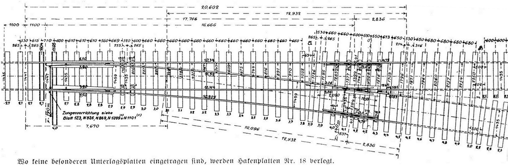
One downer is that hes unwilling to state what the length of each particular turnout would be, despite the fact that hes been building them for decades and one would hope for a modicum of consistency. However, as a rough guide, I offer you this site:
http://www.oldpullmanmodelrailroads.com
Select Catalog, and then the Turnout/Crossing Dimensions link.
Be forewarned that this site could disappear at any time. He apparently decided to get out of the business a few years ago and just disappeared or, at least, he ignores any efforts to get in touch with him. There were various rumors about him turning it over to his son, or selling it to some guy in Colorado, but I never found a confirmable storyline. For whatever reason, the site is still there. Too bad he isnt he had better prices and was a bit easier to work with ;-)
For those in other parts of the world, particularly the U.K., mainland Europe, or Australia, there are certain to be custom turnout builders nearby, although I suspect their prices will be higher. However, you might even be able to find one who will build you a 1:35 scale turnout, but dont count on it. Besides any jigs, there are dozens of sub-tasks that these fellows do by routine, and your asking for a 1:35 turnout will likely cause him to ponder everything that he would need to do differently if it doesnt drive him to tell you to go look elsewhere. However, you might get somewhere if you ask him to build a 1:32 turnout, but just to make it about 4mm narrower overall. Maybe give him a piece of the Trumpeter track to use as a guide. No guarantees. Also note that it depends on what rail stock any particular builder has available. Hopefully he has or can get 200-205, but remember that these guys are used to using much heavier rail for 45mm turnouts most of them destined to be installed outdoors, where ruggedness is an important factor. Also if he doesnt have what you want on hand, hell have an expensive minimum order through his supplier, and will want to pass part of that on to you.
If you havent considered it, one advantage of buying a custom turnout means that you dont need to mess around with carefully cutting away plastic ties. Another benefit is that it will come with a soldered metal frog, and guard rails; no plastic at all.
This process/project - or at least my description of it - is turning out to be much longer than I had anticipated, so Ill end Part 2 here. Having learned a lesson, I wont state how many additional sections there will be. When I first considered this project, it seemed quite straight-forward in my mind, and I could clearly envision all the required steps. That was before I fully realized the implications of explaining it to someone without a model railroad background.