Ok, so I've taken the plunge and finally registered on this fine website. Been away from modelling for the past 10 years or so but I've been well and truly bitten by the bug again! I've absorbed a huge amount of inspiration form these forums while lurking around over the past few months and taking on board tips and advice to hopefully enable me to brush up on and develop my skills.
So, I've just started on a build of the Tamiya Challenger I. This will be built as a mk.2 in green/black camo, but with little twist in that it'll be radio controlled.
I'll be striving to share my progress as much as possible and have almost completed the suspension which, after some modification of the rbmodels Abrams suspension kit, will be fully functional.
Pics will be posted soon for anyone who's interested. I'm keen to keep the suspension movement as in scale as possible,so wondering if anyone could offer some advice at this early stage with specs? I believe that the Challenger 1 has a ground clearance of 500mm, with 450mm of wheel travel available. Does anyone know what the min/max levels of ground clearance would be if the suspension was fully compressed/uncompressed?
Hosted by Darren Baker
Challenger r/c conversion

Doakie

Joined: June 30, 2013
KitMaker: 6 posts
Armorama: 6 posts

Posted: Sunday, June 30, 2013 - 05:20 AM UTC
Keef1648

Joined: January 23, 2008
KitMaker: 1,240 posts
Armorama: 1,192 posts

Posted: Sunday, June 30, 2013 - 09:04 AM UTC
Excellent, I look forward to seeing and reading more of this fine project.
Keith.
Keith.


Doakie

Joined: June 30, 2013
KitMaker: 6 posts
Armorama: 6 posts

Posted: Monday, July 01, 2013 - 08:52 AM UTC
Thanks Keith - I'll do my best to oblige!
Making steady progress with the suspension, with only one more suspension arm left to install.
It's more of an engineering project at the moment with very little in the way of modelling going on.
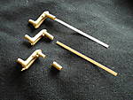
The picture shows the various stages of assembly of the suspension arms.
The suspension arm at the bottom is the Tamiya part.
In the middle, you can see the RB Model parts alongside the suspension arm. The brass collar is superglued onto the hull locating lug of the suspension arm and the metal strip that acts as a torsion bar, is superglued (or soldered) into the brass collar.
At the top of the picture you can see the assembled suspension arm. The small part of plastic on the suspension arms that locates the arm at the correct angle on the hull has the be removed and sanded smooth.
More updates soon...
Making steady progress with the suspension, with only one more suspension arm left to install.
It's more of an engineering project at the moment with very little in the way of modelling going on.
The picture shows the various stages of assembly of the suspension arms.
The suspension arm at the bottom is the Tamiya part.
In the middle, you can see the RB Model parts alongside the suspension arm. The brass collar is superglued onto the hull locating lug of the suspension arm and the metal strip that acts as a torsion bar, is superglued (or soldered) into the brass collar.
At the top of the picture you can see the assembled suspension arm. The small part of plastic on the suspension arms that locates the arm at the correct angle on the hull has the be removed and sanded smooth.

More updates soon...

Doakie

Joined: June 30, 2013
KitMaker: 6 posts
Armorama: 6 posts

Posted: Wednesday, July 03, 2013 - 10:17 AM UTC
12 wheels now on my wagon!
Not fully secure yet as the suspension's only dry fitted at the moment for fine tuning and cosmetic work on the hull, but it's still functional.
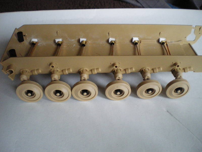
Looks like it's on stilts at the moment being uncompressed, but once the r/c gear and some lead ballast is in place, it will compress and level out at the required ride height.
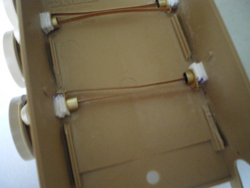
As I mentioned earlier, the RB Models suspension kit was designed for the Trumpeter Abrams, so some modifications were required in order to fit it to the Tamiya Chally.
First of all, the holes on the hull for the suspension arms were drilled out to 4mm.
Some 4mm dia brass tube with a wall thickness of 0.5mm was then cut into 12 sections, appx 15mm in length. These were then secured into the the holes in the hull using cyano.
These sections of tubing were sheaths which the RB Model brass part that attaches to the plastic suspension arm, fits into perfectly.
The RB Model kit also supplies etched brass mounting points for the torsion bars. These had the be trimmed at the bottom before fitting over the 'sheaths' due to the Chally suspension siting lower in the hull than the Abrams. Some plasticard was placed between the etched parts and the inner hull to provide strength and cyanoed in place taking care not to block the opening for the torsion bars.
Some more photos below. Any comments and advice most welcome!
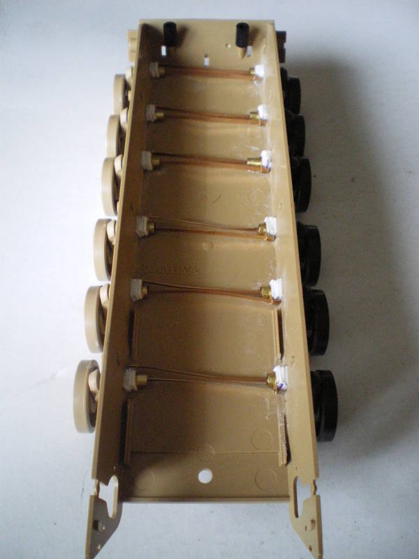
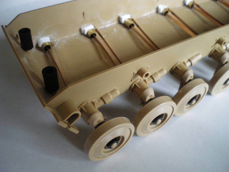

Not fully secure yet as the suspension's only dry fitted at the moment for fine tuning and cosmetic work on the hull, but it's still functional.

Looks like it's on stilts at the moment being uncompressed, but once the r/c gear and some lead ballast is in place, it will compress and level out at the required ride height.

As I mentioned earlier, the RB Models suspension kit was designed for the Trumpeter Abrams, so some modifications were required in order to fit it to the Tamiya Chally.
First of all, the holes on the hull for the suspension arms were drilled out to 4mm.
Some 4mm dia brass tube with a wall thickness of 0.5mm was then cut into 12 sections, appx 15mm in length. These were then secured into the the holes in the hull using cyano.
These sections of tubing were sheaths which the RB Model brass part that attaches to the plastic suspension arm, fits into perfectly.
The RB Model kit also supplies etched brass mounting points for the torsion bars. These had the be trimmed at the bottom before fitting over the 'sheaths' due to the Chally suspension siting lower in the hull than the Abrams. Some plasticard was placed between the etched parts and the inner hull to provide strength and cyanoed in place taking care not to block the opening for the torsion bars.
Some more photos below. Any comments and advice most welcome!


Doakie

Joined: June 30, 2013
KitMaker: 6 posts
Armorama: 6 posts

Posted: Saturday, January 17, 2015 - 01:19 AM UTC
Time to resurrect this topic methinks...
It's been well over a year since I last posted, so apologies for starting something and not following through.
It's been a very productive (relatively speaking) 16 or so months for this particular project.
It was a bit of a crazy notion that I had tbh.
I mean who thinks of converting a static Tamiya Challenger 1 into a fully functional r/c tank, considering that the last time they made a kit was about 10 years ago. Madness!
Quick update as to where I am with this;
- Shortly after my last post, I junked the workable suspension components components previously installed. As mentioned earlier in this topic, they were designed for the Trumpeter Abrams and I wasn't happy with their functionality. This is not a criticism of the suspension parts, more my skills at the time and the fact that the parts were heavily modified to fit the Chally hull.
- A spare hull was duly purchased as well as an r/c conversion kit from www.35rctank.com. These conversion kits are superbly engineered and provide fully proportional movement, turret rotation, gun elevation/stabilisation/recoil/flash, co-axial mg flash and sound!
- However, this particular conversion kit was specifically designed for a Tamiya Challenger 2 kit. This is partly the reason why I haven't posted for so long as I knew that it would push my modelling and engineering skills to their limit as a huge amount of modification would be required and I wanted to be confident that I could make the project work before posting any more updates. Sheer laziness is the other reason I haven't posted for so long...
- So, current status is as follows;
New workable suspension installed.
Tank has full motion control via twin 280 carbon brush motors, Fruil metal tracks and heavily modified Tamiya Chally 1 / 35rctank drive sprockets. This was the *easy* part of the project as the Tamiya Chally 1 and 2 hulls are effectively the same ensuring the conversion components fitted perfectly.
Turret rotates 360deg after a donor turret ring from a Tamiya Chally 2 kit was transplanted onto the Chally 1 in order that the turret ring gear from the conversion kit would be compatible.
Much, much more extensive modification was required to the turret and the conversion components to ensure that the various servos and electronics would fit and operate.
Thankfully they do and I now have a full-option 1/35 r/c Chally 1

Power is provided by a compact 860mAh 7.4v lipo power pack and the radio gear is 5 channel, 2.4GHz with a micro receiver which fits snugly in the hull along with the power pack.
Now that the conversion components are fully installed and working, I'm now in a position to start posting regular updates, pictures of progress so far and to actually start finishing the kit off - a point I thought I'd never get to!
Thanks for reading!
PS - what is the preferred image size for posting?
It's been well over a year since I last posted, so apologies for starting something and not following through.
It's been a very productive (relatively speaking) 16 or so months for this particular project.
It was a bit of a crazy notion that I had tbh.
I mean who thinks of converting a static Tamiya Challenger 1 into a fully functional r/c tank, considering that the last time they made a kit was about 10 years ago. Madness!
Quick update as to where I am with this;
- Shortly after my last post, I junked the workable suspension components components previously installed. As mentioned earlier in this topic, they were designed for the Trumpeter Abrams and I wasn't happy with their functionality. This is not a criticism of the suspension parts, more my skills at the time and the fact that the parts were heavily modified to fit the Chally hull.
- A spare hull was duly purchased as well as an r/c conversion kit from www.35rctank.com. These conversion kits are superbly engineered and provide fully proportional movement, turret rotation, gun elevation/stabilisation/recoil/flash, co-axial mg flash and sound!
- However, this particular conversion kit was specifically designed for a Tamiya Challenger 2 kit. This is partly the reason why I haven't posted for so long as I knew that it would push my modelling and engineering skills to their limit as a huge amount of modification would be required and I wanted to be confident that I could make the project work before posting any more updates. Sheer laziness is the other reason I haven't posted for so long...
- So, current status is as follows;
New workable suspension installed.
Tank has full motion control via twin 280 carbon brush motors, Fruil metal tracks and heavily modified Tamiya Chally 1 / 35rctank drive sprockets. This was the *easy* part of the project as the Tamiya Chally 1 and 2 hulls are effectively the same ensuring the conversion components fitted perfectly.
Turret rotates 360deg after a donor turret ring from a Tamiya Chally 2 kit was transplanted onto the Chally 1 in order that the turret ring gear from the conversion kit would be compatible.
Much, much more extensive modification was required to the turret and the conversion components to ensure that the various servos and electronics would fit and operate.
Thankfully they do and I now have a full-option 1/35 r/c Chally 1


Power is provided by a compact 860mAh 7.4v lipo power pack and the radio gear is 5 channel, 2.4GHz with a micro receiver which fits snugly in the hull along with the power pack.
Now that the conversion components are fully installed and working, I'm now in a position to start posting regular updates, pictures of progress so far and to actually start finishing the kit off - a point I thought I'd never get to!
Thanks for reading!
PS - what is the preferred image size for posting?

Doakie

Joined: June 30, 2013
KitMaker: 6 posts
Armorama: 6 posts

Posted: Sunday, January 18, 2015 - 04:01 AM UTC
Ok, so I now have a few photos to share that will hopefully illustrate my progress to date.
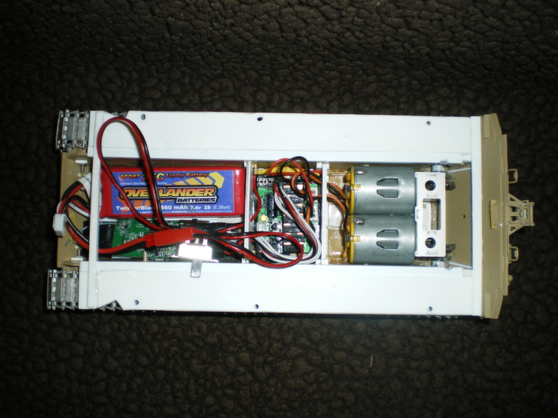
This is the lower hull stuffed full with the power pack, micro receiver, control board and twin motors. The on/off switch will be located below the driver's hatch to enable easy access.
I've added some plasticard bulkheads and strengthening ribs to the hull to improve overall rigidity. Note the 3 holes on each of the strips of plasticard that are positioned above the road wheels - these are M2 washers sandwiched between two strips of plasticard. This is to allow the upper and lower hull sections to be secured more accurately with M2 x 6mm bolts. As the hull sections will have to be able to be separated in order to allow access to the rc components, I wanted to ensure a tight fit to reduce panel gaps as much as possible.
In the following picture you can see where the bolts will locate - M2 nuts again sandwiched between plasticard. Not the neatest piece of work, but it does the job.
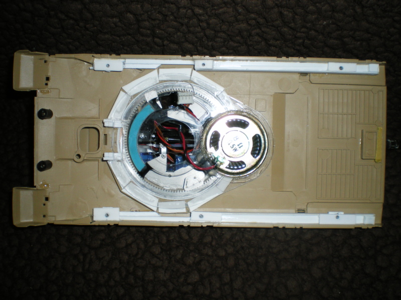
This picture also shows the speaker assembly and pieces of plasticard for locating and securing the turret ring that was donated from a Tamiya Chally 2. Again, not the neatest of jobs.
Next pic shows some of the movement of the workable suspension.
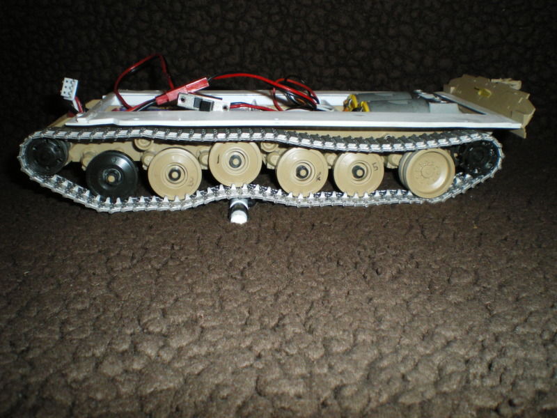
Track tension will be achieved by moving the front idler wheels which are secured to the hull with an M2 bolt as supplied in the kit. Using a small (size #000 I think) screwdriver, I can loosen the bolts through the gaps in the idler wheels and adjust as required.
The idler and road wheels will be secured to their suspension arms using small brass spacers, replacing the kit supplied polycaps. This provides a tighter and stronger fitment.
Note the Chally 2 road wheel and missing rear return roller - these are just temporary additions/omissions while things are being tested.
Final pic for the time being is a view of the turret components.
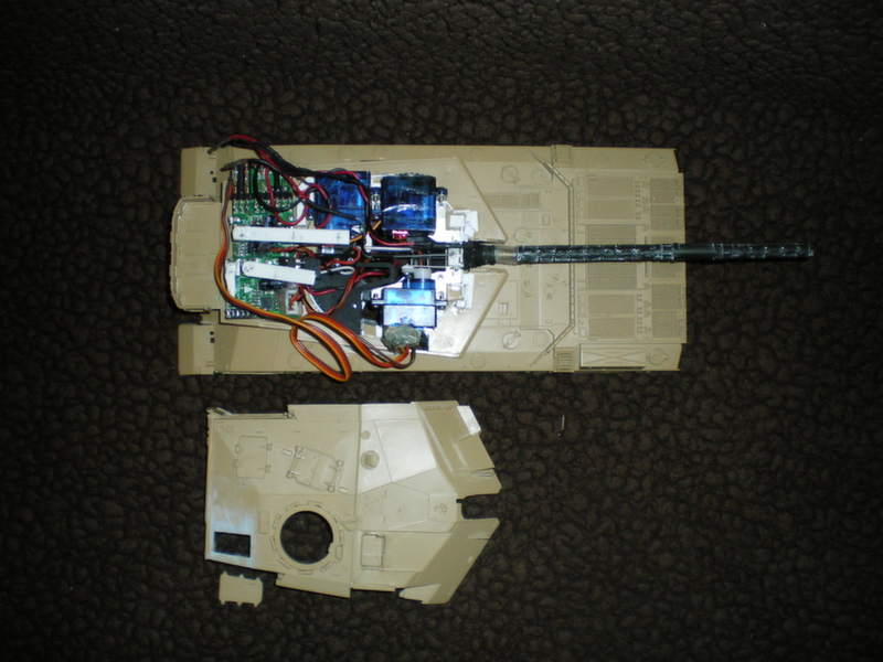
There are 3 servos (the transparent blue boxes in the photo) which control the main turret functions;
Top left: main gun recoil
Top right: turret rotation
Bottom: main gun elevation
You can also make out other electronic control boards at the rear of the turret for gun stabilisation and sound.
All of this creates an extremely tight fit. For the Chally 2 kit that this conversion is intended for, parts and instructions are included for a snap-fit method of securing the top and bottom parts of the turret. However, with the Chally 1 the two parts will just pop apart so I am going to have to permanently fix them together.
Bit of a risk this as I won't be able to service the servos if they malfunction but hey ho...
By doing this, I also prevent access to 3 switches on the control board that adjust and fine tune volume and main gun stabilisation. To overcome this, I've secured plasticard strips to the switches which can now be adjusted via the commander, loaders and rear hatches (after the rear hatch was razor sawed off).
More updates soon and I will have a short video of it in action very soon.
Thanks for looking!

This is the lower hull stuffed full with the power pack, micro receiver, control board and twin motors. The on/off switch will be located below the driver's hatch to enable easy access.
I've added some plasticard bulkheads and strengthening ribs to the hull to improve overall rigidity. Note the 3 holes on each of the strips of plasticard that are positioned above the road wheels - these are M2 washers sandwiched between two strips of plasticard. This is to allow the upper and lower hull sections to be secured more accurately with M2 x 6mm bolts. As the hull sections will have to be able to be separated in order to allow access to the rc components, I wanted to ensure a tight fit to reduce panel gaps as much as possible.
In the following picture you can see where the bolts will locate - M2 nuts again sandwiched between plasticard. Not the neatest piece of work, but it does the job.

This picture also shows the speaker assembly and pieces of plasticard for locating and securing the turret ring that was donated from a Tamiya Chally 2. Again, not the neatest of jobs.
Next pic shows some of the movement of the workable suspension.

Track tension will be achieved by moving the front idler wheels which are secured to the hull with an M2 bolt as supplied in the kit. Using a small (size #000 I think) screwdriver, I can loosen the bolts through the gaps in the idler wheels and adjust as required.
The idler and road wheels will be secured to their suspension arms using small brass spacers, replacing the kit supplied polycaps. This provides a tighter and stronger fitment.
Note the Chally 2 road wheel and missing rear return roller - these are just temporary additions/omissions while things are being tested.
Final pic for the time being is a view of the turret components.

There are 3 servos (the transparent blue boxes in the photo) which control the main turret functions;
Top left: main gun recoil
Top right: turret rotation
Bottom: main gun elevation
You can also make out other electronic control boards at the rear of the turret for gun stabilisation and sound.
All of this creates an extremely tight fit. For the Chally 2 kit that this conversion is intended for, parts and instructions are included for a snap-fit method of securing the top and bottom parts of the turret. However, with the Chally 1 the two parts will just pop apart so I am going to have to permanently fix them together.
Bit of a risk this as I won't be able to service the servos if they malfunction but hey ho...
By doing this, I also prevent access to 3 switches on the control board that adjust and fine tune volume and main gun stabilisation. To overcome this, I've secured plasticard strips to the switches which can now be adjusted via the commander, loaders and rear hatches (after the rear hatch was razor sawed off).
More updates soon and I will have a short video of it in action very soon.
Thanks for looking!

Doakie

Joined: June 30, 2013
KitMaker: 6 posts
Armorama: 6 posts

Posted: Tuesday, January 20, 2015 - 02:28 AM UTC
Here's a very basic video showing the main functions of the conversion:
http://youtu.be/ka6MHrWsHgke
http://youtu.be/ka6MHrWsHgke
xMatsx

Joined: June 21, 2014
KitMaker: 2 posts
Armorama: 2 posts

Posted: Sunday, January 25, 2015 - 06:34 AM UTC
Nicely done! This is actually one of the reasons that hooked me to this hobby. I was planning to buy the rc kit for bradley and put it inside Meng's M3A3 but theyre always out of stock every time I check on them. I'll be looking forward for your progress on this project. Keep up the good work!
 |


