

July 1, 2014- Happy Canada Day!
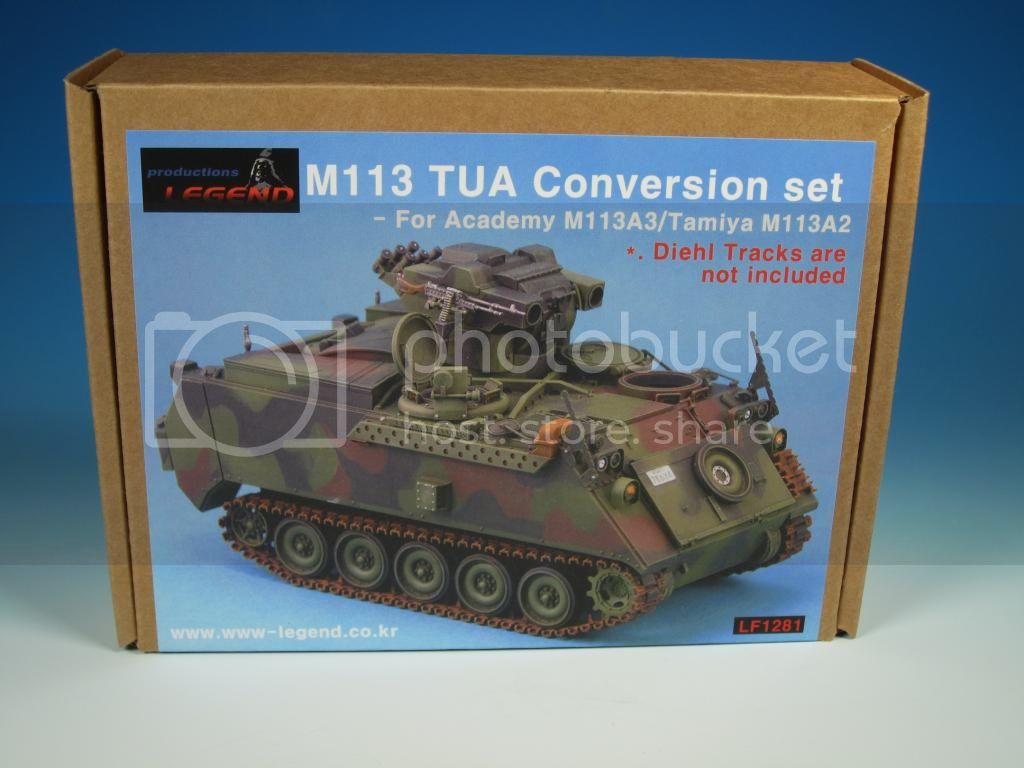
What a great day to start a build review blog on the new Legend Productions LF1281 M113 TUA Conversion Set.
The conversion consists of 64 resin parts and 130 photo etched parts. The conversion is designed to be paired with the Academy M113A2 kit or the Tamiya M113A2/M113A3 kits.
However, you can use one of the other Academy M113 based kits as long as it includes the external fuel tanks such as the Academy M981 FIST-V.
The tracks in your donor M113 kit of choice will have to be changed to Diehl track. The Diehl tracks are not included in the conversion. This type of track was found on all Canadian M113A2 Tow Under Armour vehicles. HKCW made a set of M113 Diehl track and AFV Club makes a set M113 Diehl tracks. The Perfect Scale Modellbau M113 513B Diehl track is a newer version and not correct for the M113A2 TUA.
My review build blog will stick to the contents included in the conversion set. There will be no exchanging parts, no adding other aftermarket parts, no additional detailing, and no painting. Those considering building this conversion can assess the need to add additional details based on their skills, abilities, and desire.
Where applicable I will provide recommendations for further detailing and options for the build. The Canadian M113A2 TUA was modified over the time period of its service and all of the details included in the conversion may not be applicable depending on the timeline and location of deployment.
During this build review if you have questions ask. If you have additional points to add regarding the conversion or the actual vehicle please do so.
Legend Productions has done a great job of showing the completed conversion in the raw and in NATO camouflage on their site...
http://www.www-legend.co.kr/01_afv01.html?table=product&st=view&page=1&id=559&limit=&keykind=&keyword=&bo_class=1&fpage=&spage=
http://www.www-legend.co.kr/07_gal01.html?table=product&st=view&page=1&id=550&bo_class=7
I have had the fortune of working with the M113A2 TUA on exercises in Canada, as part of my old Regiment during an UNPROFOR deployment, and a very nicely restored M113A2 TUA is a 10 minute drive from my house for instant reference.
The Legend Productions conversion resin castings at first, second, and third glance are amazingly detailed. They are truly some of the finest resin castings I have seen.
I'll provide a bit of background on the Canadian M113A2 TUA before the build begins but that's for the next entry...
Hosted by Darren Baker
Legend Productions M113A2 Tow Under Armour

LeoCmdr

Joined: January 19, 2005
KitMaker: 4,085 posts
Armorama: 3,917 posts

Posted: Tuesday, July 01, 2014 - 03:18 PM UTC

C_JACQUEMONT

Joined: October 09, 2004
KitMaker: 2,433 posts
Armorama: 2,325 posts

Posted: Tuesday, July 01, 2014 - 05:22 PM UTC
Looks like a great thread starting, thanks!
I'm bookmarking this one as I plan to build this conversion at some stage.
Cheers,
Christophe
I'm bookmarking this one as I plan to build this conversion at some stage.
Cheers,
Christophe
LeoCmdr
Joined: January 19, 2005
KitMaker: 4,085 posts
Armorama: 3,917 posts
Posted: Wednesday, July 02, 2014 - 08:32 AM UTC
The Canadian use of M113 for anti-tank / anti-armour purposes dates back to the 1960s with the mounting of the M40 106 mm Recoilless Rifle with the M79 mount on Canadian M113A1s. This was followed by Canadian M113A1s with dual post mounted SS-11B anti-tank missiles.
Both the M40 and the SS-11B missiles were used on Canadian M113A1s until the 1970s when they were replaced in the Regular Force Army by the M113A1 TOW missile carrier.
From about 1976 the M113A1 and later M113A2 (external fuel tanks added) TOW missile carriers formed the brunt of the Anti-Armour Defence Platoons within the Infantry Battalions. The TOW missile launcher was pedestal mounted on the M113 hull and could be raised through the top hatch to the firing position. While having a relatively low silhouette, the crew was exposed to direct and indirect enemy fire while in the firing /tracking position. Another limitation was that only one missile was ready for firing at any given time.
Norway had fielded the NM142 based on the M113 hull paired with the Kvaerner Eureka Armoured Launching Turret. The turret has two TOW missile launchers on either side of the gunner's turret. The turret provided the gunner with armoured protection and an elevated platform from which tactical hull down positions could be obtained in order to maximize cover and line of sight for tracking the missile to the intended target. Canada created 72 M113A2 TOW Under Armour carriers using the Kvaerner Eureka turret on a modified M113A2 hull and put them into service in 1990. I believe the Kvaerner Eureka turrets were built in Canada under licence and the M113A2s modified accordingly. For a period of time they served along side the M113A2 pedestal mounted TOW carriers.
The M113A2 TOW served in Canada, Germany, Croatia, Bosnia, and Kosovo. The vehicles were highly feared and despised by belligerent forces during deployments and at least one M113A2 TUA was destroyed by enemy fire during the UNPROFOR mission.
Over the period of service the vehicles did receive modifications which I will speak to along with some technical aspects as the build progresses.
Next up, what is included in the Legend Productions conversion...
LeoCmdr
Joined: January 19, 2005
KitMaker: 4,085 posts
Armorama: 3,917 posts
Posted: Wednesday, July 02, 2014 - 04:15 PM UTC
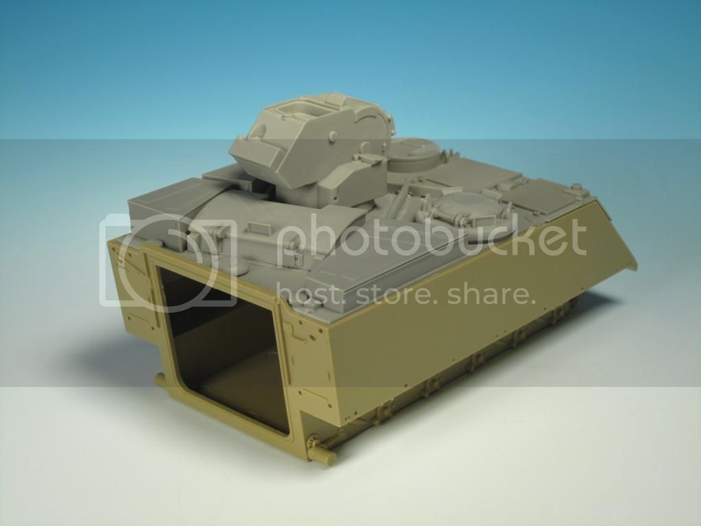
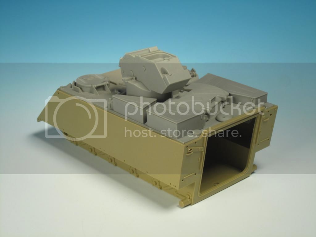
The conversion set includes all the main components for the hull and turret to build a Canadian M113A2 TUA.
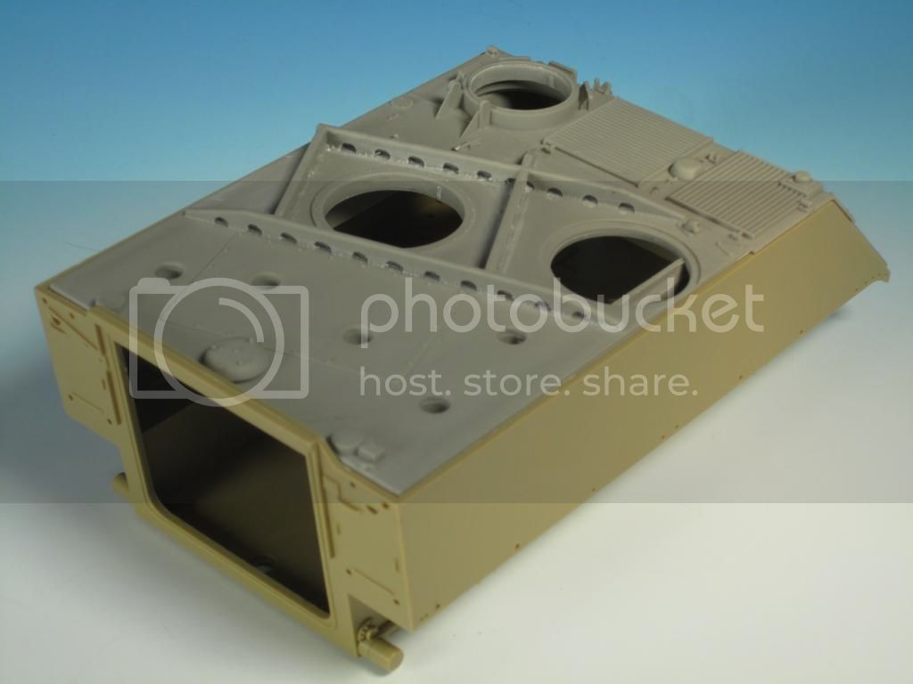
The upper hull is provided in full resin. The casting blocks on the hull rear and sides will have to be cut off in order for the piece to fit into the donor hull.
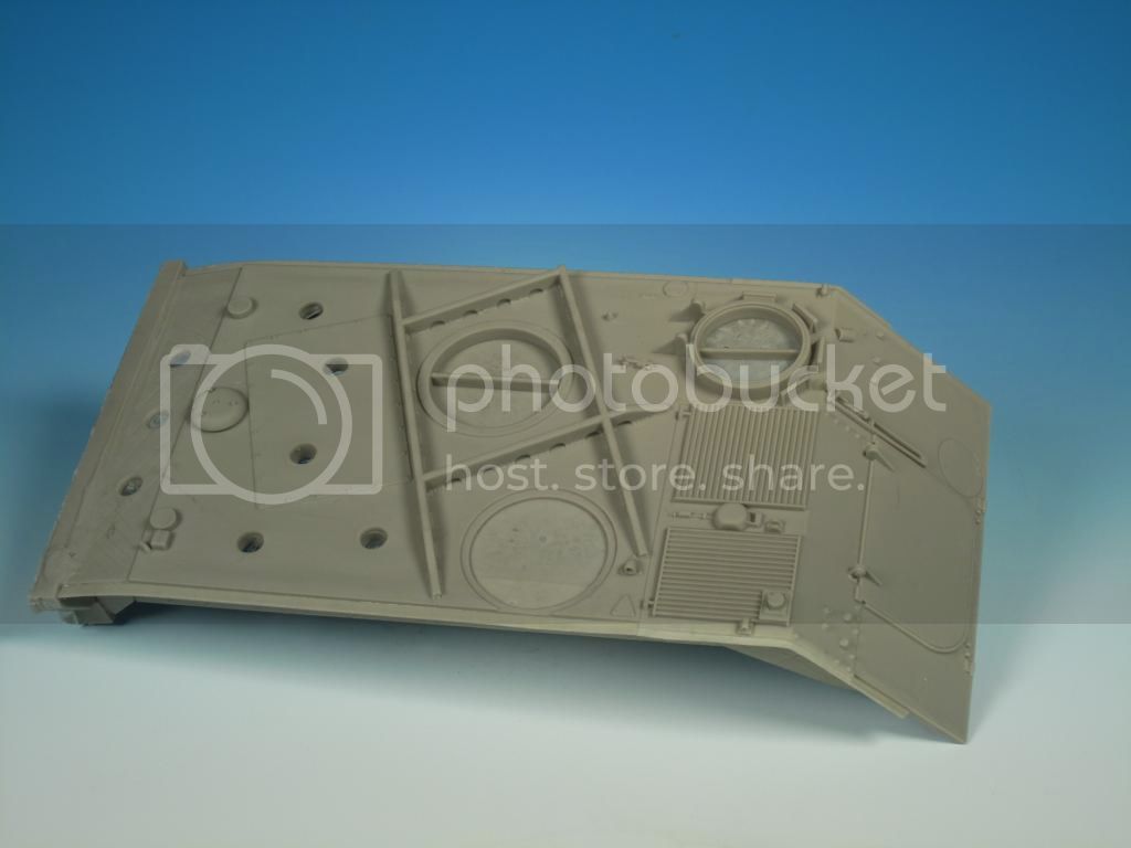
The upper hull modifications are obvious with the reinforcing ribs criss-crossing on the hull top.
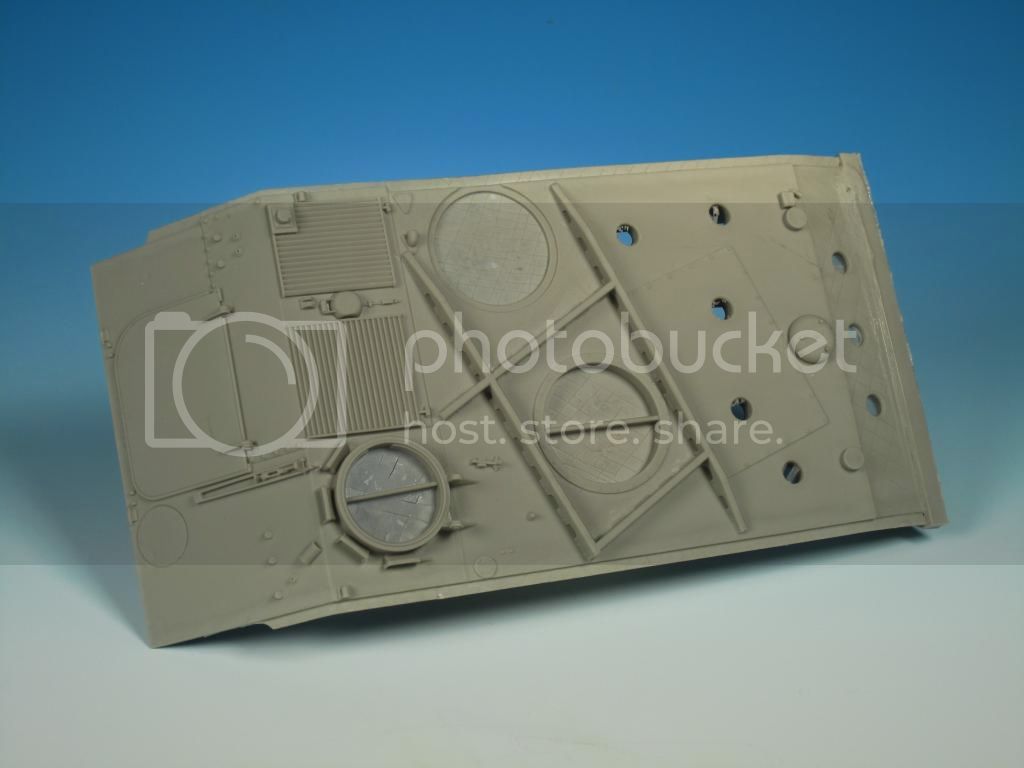
The driver's and commander's hatches as well as the turret hole have a fine skin of resin that can easily be removed. Seen at the upper hull rear are the large locating holes for the missile loading hatch as well as the top mounted stowage bins.

The hull parts consist of the following:
1. Missile loading hatch
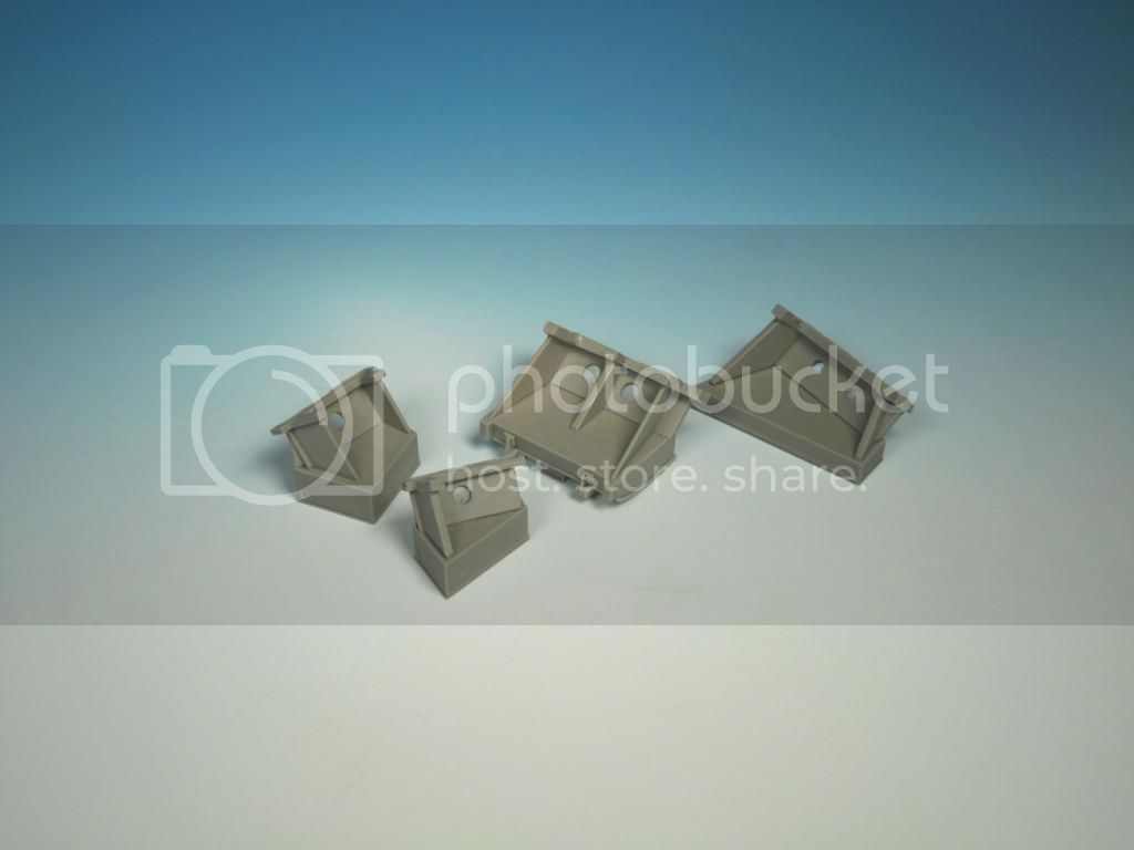
2. 3 x hull top stowage bins
3. Commander's cupola and hatch
4. Driver's hatch
5. Mirrors
6. Headlight, taillights, signal lights, blackout marker, and horn
7. 20 Litre POL and water cans
8. Spare road wheel
9. Grouser racks
10. 2 x antenna mounts
11. Extended exhaust components
12. TCCCS box (Tactical Command and Control Communications System)
13. GPS antenna
14. External fire extinguisher cover
15. Trim vane and missile loader's hatch hinges

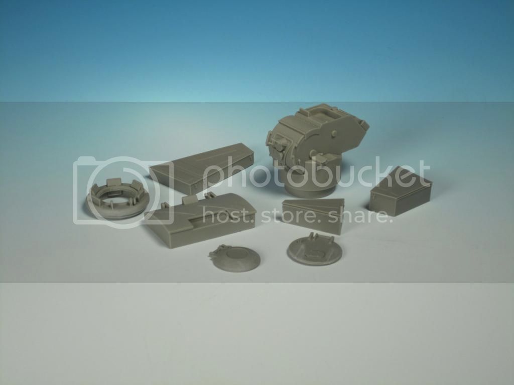
The armoured turret parts consist of the following:
1. Armoured turret
2. 2 x TOW missile launchers
3. Turret hatch
4. 7 x Multi-Barrel Grenade Dischargers (only 6 are used)
5. C6 GPMG
6. C6 Mount
7. 7.62 mm ammunition tray and box
8. 7.62 mm ammunition belt
9. 3 x TOW missile ends (only 2 are used)
10. Commander CCTAS (Crew Commander's Target Acquisition System)
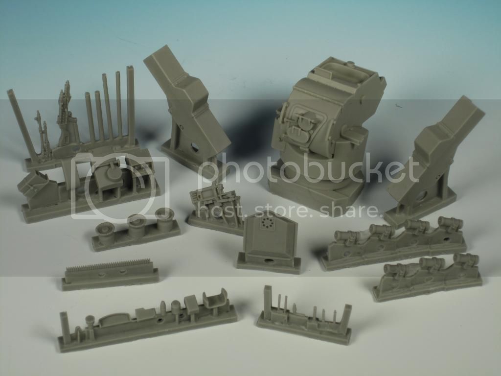
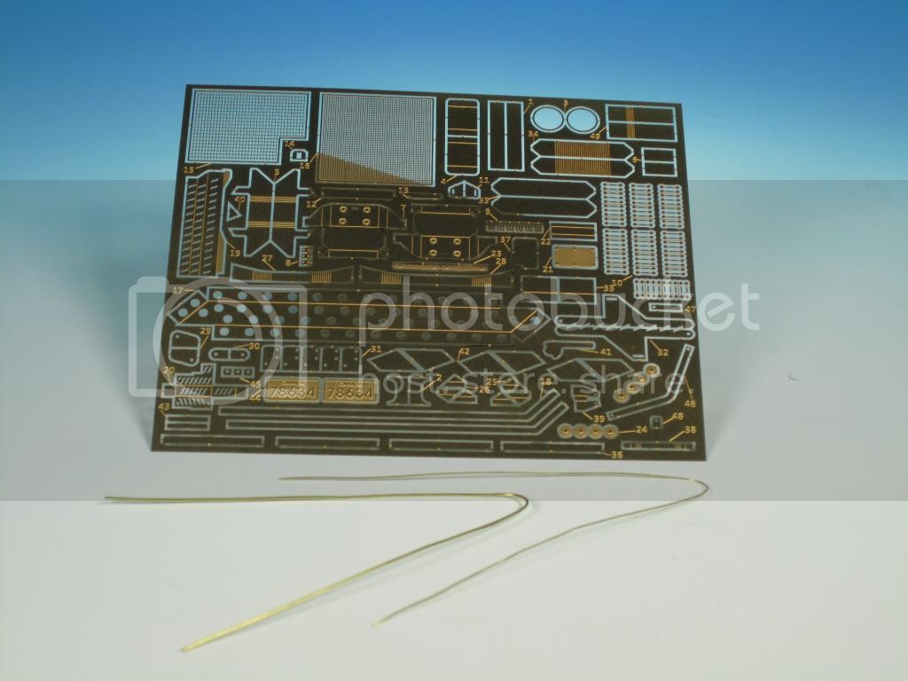
Also included are a very good supply of three different sizes of resin bolts. Pay attention to the instructions as to where they are used.
A jam packed PE fret is included. These parts will detail both the resin parts as well as the donor kit hull. Ranging from tie downs to the intricate extended exhaust to the wire cutters the PE parts will make this conversion pop and add a significant level of detail. Two different diameters of brass wire are included for the mirror arms and the turret lifting eyes.
The instructions are provided in colour on a two sided sheet. You really need to study the parts and where they go. Don't expect a fall together Tamiya kit. You will need to plan the build from start to finish to mesh the resin and PE parts with the donor kit parts. The instructions also indicate minor modifications required to the donor kit lower hull in order to properly fit the resin upper hull.
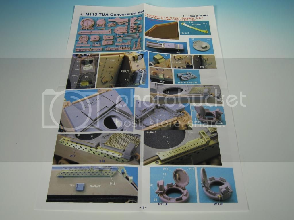

I can't reiterate enough the quality and detail included in the resin castings. The disadvantage of the high quality resin parts is that there are significant casting blocks to be removed from the parts. Planning, patience, and careful cutting and sanding will pay off in order to get the parts into a useable state.
The upper hull is provided in full resin. The casting blocks on the hull rear and sides will have to be cut off in order for the piece to fit into the donor hull.
The upper hull modifications are obvious with the reinforcing ribs criss-crossing on the hull top.
The driver's and commander's hatches as well as the turret hole have a fine skin of resin that can easily be removed. Seen at the upper hull rear are the large locating holes for the missile loading hatch as well as the top mounted stowage bins.
The hull parts consist of the following:
1. Missile loading hatch
2. 3 x hull top stowage bins
3. Commander's cupola and hatch
4. Driver's hatch
5. Mirrors
6. Headlight, taillights, signal lights, blackout marker, and horn
7. 20 Litre POL and water cans
8. Spare road wheel
9. Grouser racks
10. 2 x antenna mounts
11. Extended exhaust components
12. TCCCS box (Tactical Command and Control Communications System)
13. GPS antenna
14. External fire extinguisher cover
15. Trim vane and missile loader's hatch hinges
The armoured turret parts consist of the following:
1. Armoured turret
2. 2 x TOW missile launchers
3. Turret hatch
4. 7 x Multi-Barrel Grenade Dischargers (only 6 are used)
5. C6 GPMG
6. C6 Mount
7. 7.62 mm ammunition tray and box
8. 7.62 mm ammunition belt
9. 3 x TOW missile ends (only 2 are used)
10. Commander CCTAS (Crew Commander's Target Acquisition System)
Also included are a very good supply of three different sizes of resin bolts. Pay attention to the instructions as to where they are used.
A jam packed PE fret is included. These parts will detail both the resin parts as well as the donor kit hull. Ranging from tie downs to the intricate extended exhaust to the wire cutters the PE parts will make this conversion pop and add a significant level of detail. Two different diameters of brass wire are included for the mirror arms and the turret lifting eyes.
The instructions are provided in colour on a two sided sheet. You really need to study the parts and where they go. Don't expect a fall together Tamiya kit. You will need to plan the build from start to finish to mesh the resin and PE parts with the donor kit parts. The instructions also indicate minor modifications required to the donor kit lower hull in order to properly fit the resin upper hull.
I can't reiterate enough the quality and detail included in the resin castings. The disadvantage of the high quality resin parts is that there are significant casting blocks to be removed from the parts. Planning, patience, and careful cutting and sanding will pay off in order to get the parts into a useable state.
C_JACQUEMONT
Joined: October 09, 2004
KitMaker: 2,433 posts
Armorama: 2,325 posts
Posted: Wednesday, July 02, 2014 - 05:26 PM UTC
Awesome presentation, thanks a million!
Cheers,
Christophe
Cheers,
Christophe

Maki


Joined: February 13, 2002
KitMaker: 5,579 posts
Armorama: 2,988 posts
Posted: Wednesday, July 02, 2014 - 10:11 PM UTC
Very informative, I like the way you started this project blog. I will be following.
Cheers,
Mario
Cheers,
Mario

LeoCmdr
Joined: January 19, 2005
KitMaker: 4,085 posts
Armorama: 3,917 posts
Posted: Wednesday, July 30, 2014 - 12:59 PM UTC
Moving along with the build the conversion starts to get prepped and fitted to the donor kit hull.
The donor kit used is the Academy M113A2. This is a great kit and will provide an excellent base for the conversion.
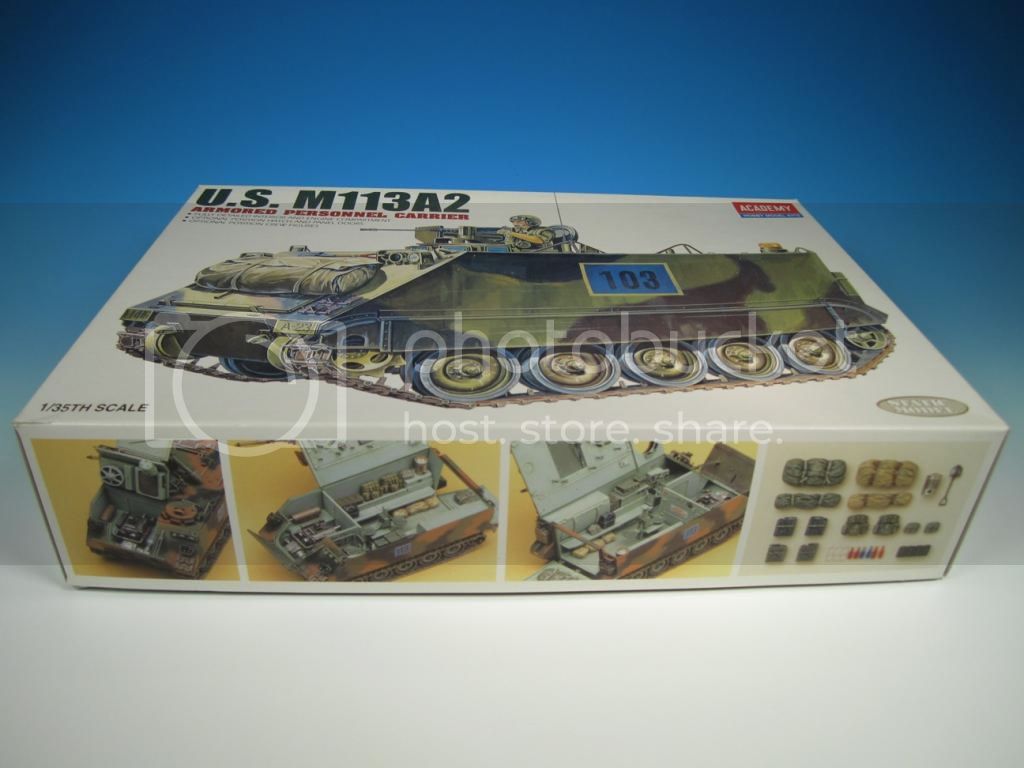
The donor kit used is the Academy M113A2. This is a great kit and will provide an excellent base for the conversion.
LeoCmdr
Joined: January 19, 2005
KitMaker: 4,085 posts
Armorama: 3,917 posts
Posted: Wednesday, July 30, 2014 - 01:04 PM UTC
The kit hull needs a bit of prep. This results in removing about 2 mm of the inside hull in order for the resin hull top to fit properly. The instructions indicate only removing plastic from the right interior but I removed it from both sides.
Here are pics showing the areas to be removed.
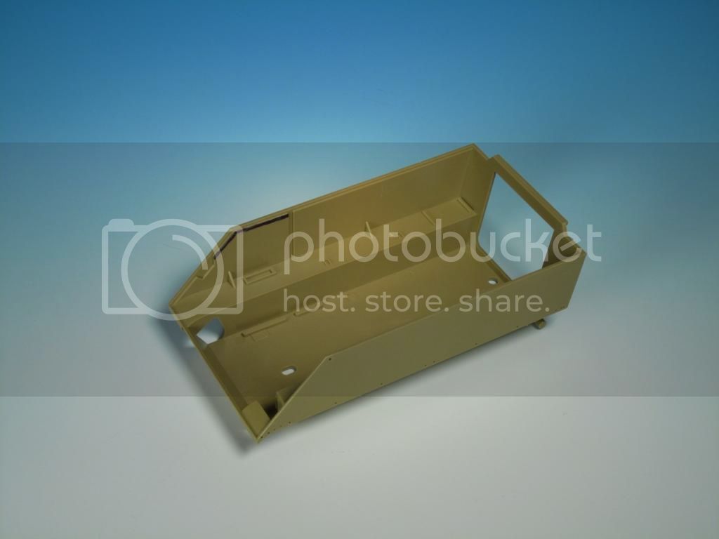

Here are pics showing the areas to be removed.
LeoCmdr
Joined: January 19, 2005
KitMaker: 4,085 posts
Armorama: 3,917 posts
Posted: Wednesday, July 30, 2014 - 01:10 PM UTC
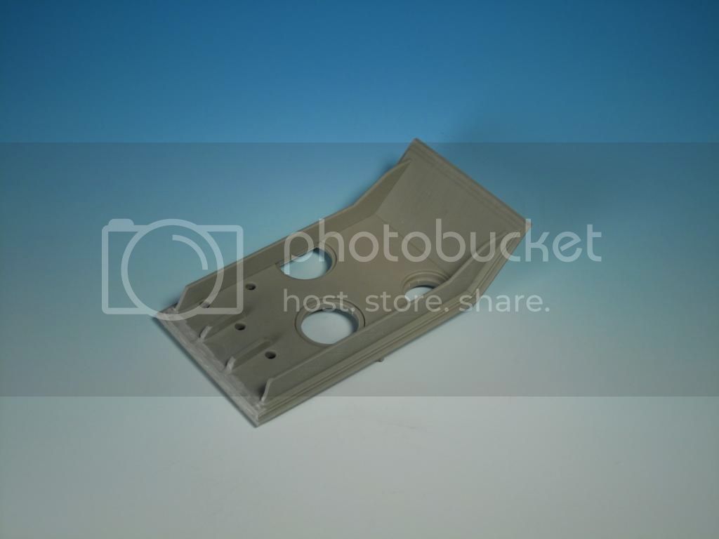
With the hull ready I test fitted the resin upper hull and realized it did not fit properly. There was an unnatural overbite on the front of the hull. Examining the parts I realized a couple of things.
The first was that Legend Productions did an excellent job on reinforcing the bottom of the resin part in order to prevent warping. The resin upper hull in my review sample is straight as a board. The excess resin on the bottom of the part interferes with the part fitting properly.
In order to get the parts fitting properly I trimmed and sanded away the resin reinforcement ribs.
LeoCmdr
Joined: January 19, 2005
KitMaker: 4,085 posts
Armorama: 3,917 posts
Posted: Wednesday, July 30, 2014 - 01:13 PM UTC
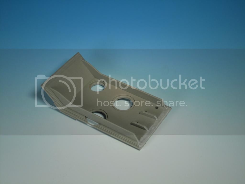
The upper hull now was a close fit for the lower hull but not what I wanted. In looking at the lower and upper hull I saw that the lower hull has a small angle and that the Legend Production part after my sanding did not.
A bit more sanding created the reverse angle I was looking for and testing fitting result in a very nice tight fit even without glue.

A bit more sanding created the reverse angle I was looking for and testing fitting result in a very nice tight fit even without glue.
LeoCmdr
Joined: January 19, 2005
KitMaker: 4,085 posts
Armorama: 3,917 posts
Posted: Wednesday, July 30, 2014 - 01:17 PM UTC
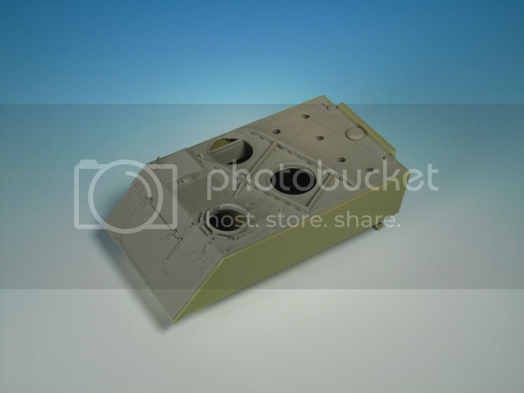
The upper hull has a great deal of accuracy but needs a bit of tweaking. Running criss cross on the upper hull are reinforcing ribs. On the real vehicle there are half moon openings along all ribs. Legend Productions has reproduced the ribs and openings faithfully but the holes need to be opened up.
With some careful drill and blade work all the holes were opened up in under an hour.

With some careful drill and blade work all the holes were opened up in under an hour.
LeoCmdr
Joined: January 19, 2005
KitMaker: 4,085 posts
Armorama: 3,917 posts
Posted: Monday, August 11, 2014 - 02:00 PM UTC
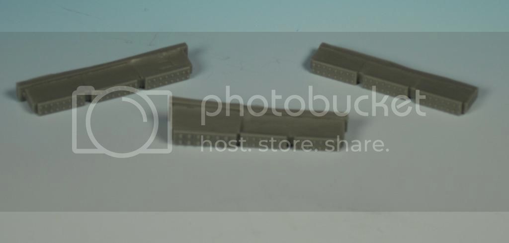
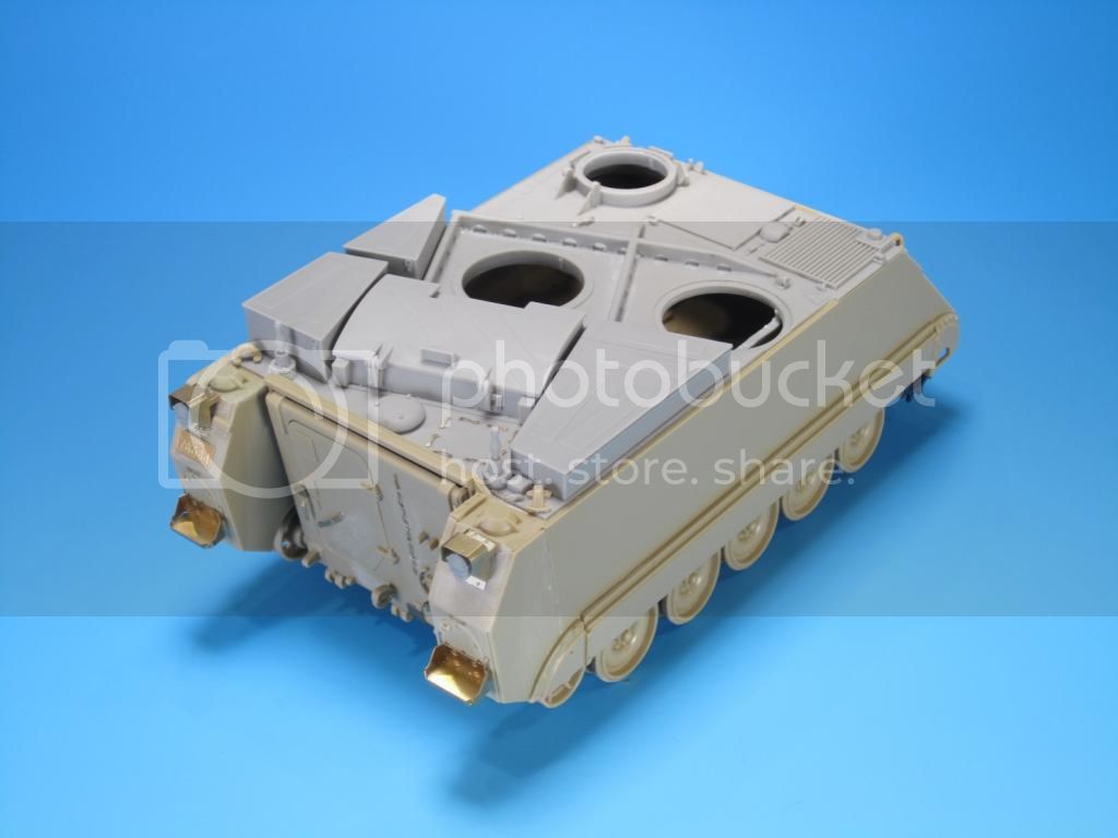
The turret bins and main turret structure have been cleaned up and test fitted.
The holes on the hull top don't pertain to any alignment lugs on the bottom of the bins. You will need to refer to the instructions or seek out reference material for the exact placement of the bins.
You can see from the first image the amount of resin pour plugs that need to be removed. A razor saw, clippers, hobby blade, and some sand paper were all that was required. Take your time and the clean up is fairly easy. All in all the clean up took me about an hour.
I have not modified the three stowage bins for the review however on the real vehicle the outer and inner edges are slightly rounded. The end edges are flat.
On the Legend Productions' bins there are strips of anti-slip. Depending on the TUA there were either strips of anti-slip or the entire top surface was covered with anti-slip.
Removed by original poster on 08/12/14 - 02:11:32 (GMT).
LeoCmdr
Joined: January 19, 2005
KitMaker: 4,085 posts
Armorama: 3,917 posts
Posted: Monday, August 11, 2014 - 02:13 PM UTC
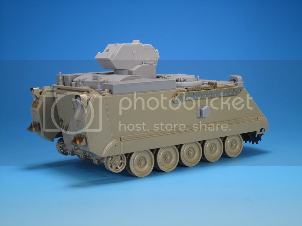
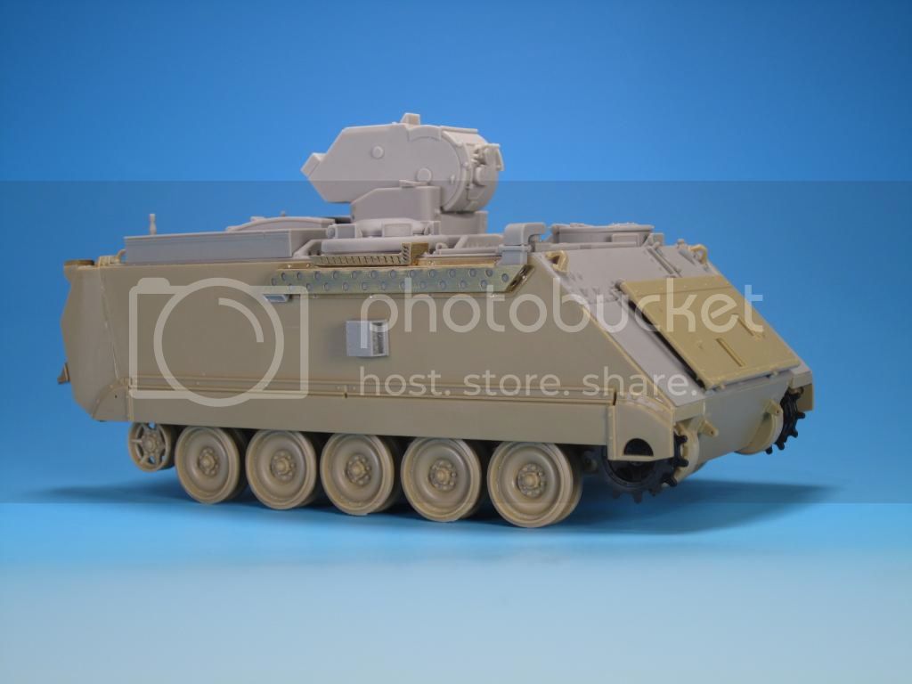
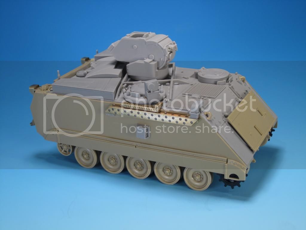
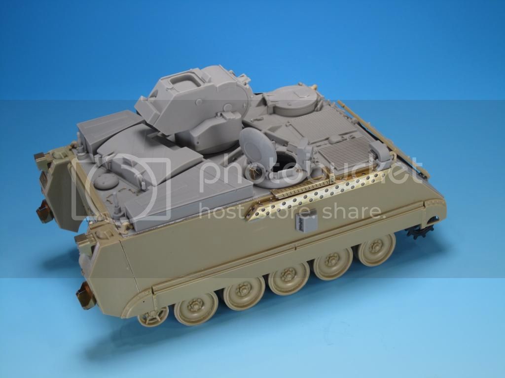
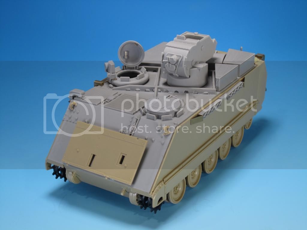
Test fitting of the three stowage bins, the missile loading hatch, the turret structure, the driver's hatch, the commander's cupola, and the commander's hatch was flawless. The parts mate very well with the resin upper hull.
You will note that both the commander's cupola and the turret have slight risers and do not sit flush on the hull top...this is 100% correct.
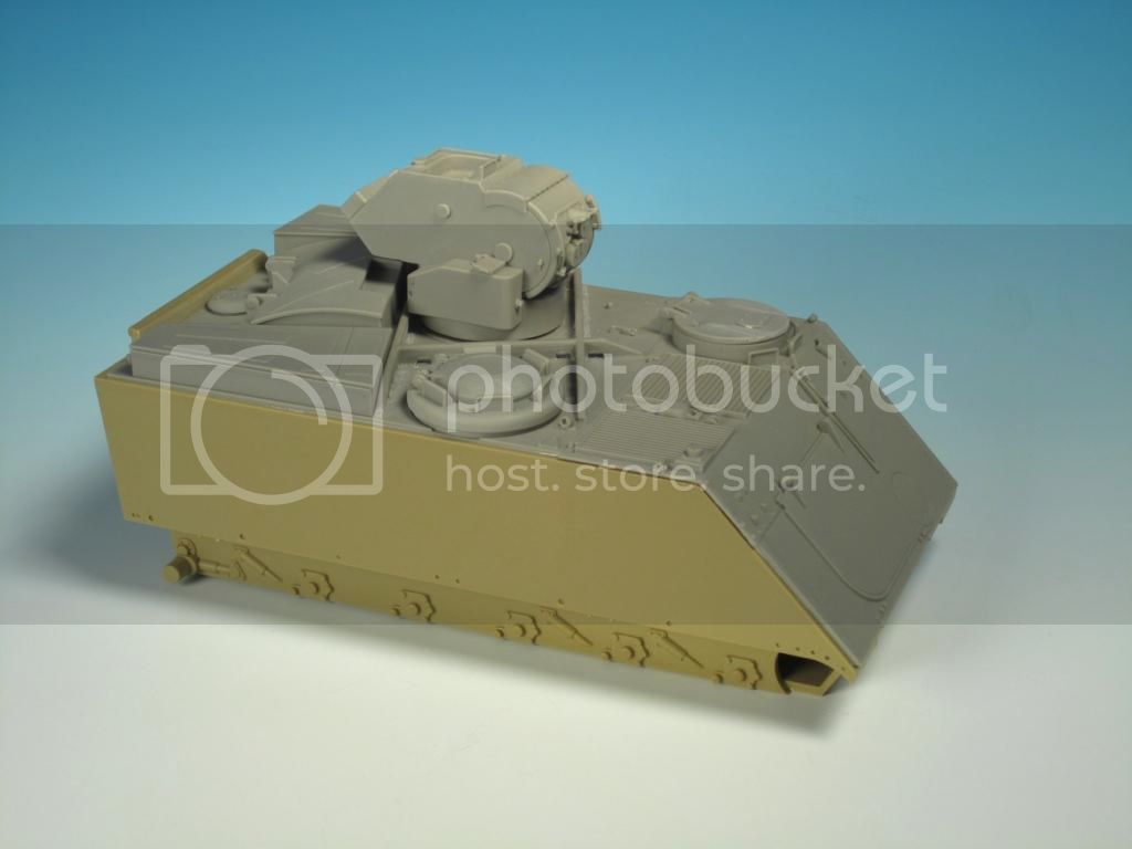

You will note that both the commander's cupola and the turret have slight risers and do not sit flush on the hull top...this is 100% correct.

grimmo

Joined: January 17, 2006
KitMaker: 752 posts
Armorama: 569 posts
Posted: Monday, August 11, 2014 - 07:57 PM UTC
great build so far. certainly better kit than the verlinden version

flugwuzzi

Joined: November 02, 2007
KitMaker: 633 posts
Armorama: 599 posts
Posted: Tuesday, August 12, 2014 - 01:35 AM UTC
Excellent Kit Build Review!
Thanks for sharing.
Cheers
Walter
Thanks for sharing.
Cheers
Walter
LeoCmdr
Joined: January 19, 2005
KitMaker: 4,085 posts
Armorama: 3,917 posts
Posted: Tuesday, October 14, 2014 - 08:02 AM UTC
With Thanksgiving in Canada literally under the belt over the weekend I finally had time for a build update.
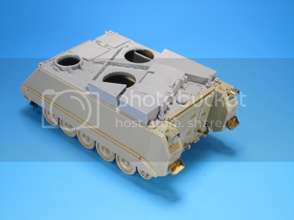
The details on the rear hull were tackled as the build continues.
The parts from the kit need some preparation for the attachment of the Legend Productions conversion parts. Namely, the areas where the rear taillights and guards needs both sanding and filling. This is a simple task and aids in the smooth attachment of the parts.
Canadian M113A2 TUAs all had the external fuel tanks on the hull so you have no option to not add them. The taillight guards are a bit different from U.S. version and Legend Productions has provided three PE parts and the resin taillight for each assembly. Careful bending of the main guard is essential in order for the other smaller PE parts to fit properly. The smaller parts consist of a vertical PE part for the resin light to attach to and a small horizontal PE part that bridges the gap between the guard and the external fuel tank. The PE guard is not exactly replicated when compared to the real thing but it is pretty close in 1/35. The resin lights should sit inside the guards so sanding the base is required as well as a bit of test fitting to ensure centering and a countersunk look in the light guard. Once assembled resin bolts were added to the upper and lower guard plates.
A total of 29 PE tie downs were added to the rear hull area. The TUA has some unique placements for the tie downs and being organized in advance assists with correct placement. The only preparation required for the tie downs was the removal of moulded on tie downs on the kits fuel tanks. I find bending the tie downs both onerous and difficult due to the unique angles and small size. I would prefer if Legend Productions included a small resin jig to assist with proper bending. I created my own jig with some scrap plastic to get the tie downs into the basic shapes.

The PE jerry can racks are straight forward and bend up nicely and securely with no issues. The resin water can and fuel can fit nice and snug in the racks once they are cleaned up and sanded.

On the rear upper hull two resin antenna mounts were added. Note that not all TUAs mounted two antennas on these locations. It was much more common to see only one antenna mounted on the right mount.
Depending on which version of the TUA you are building or where it was deployed may vary the type of antenna mount and length of the antenna. Canada adopted a short one piece antenna with a simplified mount in the early 1990s. TUA and other Canadian AFVs such as the Leopard C1 used these types of antennas. On the TUA the short antennas could be seen mounted on vehicles in Germany and in Bosnia. Over time the short antennas and mounts were replaced with standard antennas and mounts. Do your homework on the type on antenna and location as you plan your build. Only the standard antenna mount is provided in the conversion.
A PE licence plate is provided for the left fuel tank. It follows the correct sequence for a TUA.
Other details provided for the rear hull are handles and locks for the rear hatch door and a PE guard for exposed cables at the base of the ramp.

I did discover one placement issue between conversion and kits parts. On the rear upper hull the two kit lifting eyes are attached to the upper corners on the resin upper hull. Due to the size of the kit parts and the proximity of the resin bins there is overhang of the lifting eyes. The lifting eyes are too big for the correct placement. This issue is visible in Legend Productions build images and their instructions. Replacement resin lifting eyes of the corrected size should have been provided by Legend Productions to avoid this issue.
As you can see in my build images I have added the side skirts. This is personal preference and I like the look of the side skirts on the TUA.
Next up will be the hull sides including the exhaust assembly and grouser racks.
The details on the rear hull were tackled as the build continues.
The parts from the kit need some preparation for the attachment of the Legend Productions conversion parts. Namely, the areas where the rear taillights and guards needs both sanding and filling. This is a simple task and aids in the smooth attachment of the parts.
Canadian M113A2 TUAs all had the external fuel tanks on the hull so you have no option to not add them. The taillight guards are a bit different from U.S. version and Legend Productions has provided three PE parts and the resin taillight for each assembly. Careful bending of the main guard is essential in order for the other smaller PE parts to fit properly. The smaller parts consist of a vertical PE part for the resin light to attach to and a small horizontal PE part that bridges the gap between the guard and the external fuel tank. The PE guard is not exactly replicated when compared to the real thing but it is pretty close in 1/35. The resin lights should sit inside the guards so sanding the base is required as well as a bit of test fitting to ensure centering and a countersunk look in the light guard. Once assembled resin bolts were added to the upper and lower guard plates.
A total of 29 PE tie downs were added to the rear hull area. The TUA has some unique placements for the tie downs and being organized in advance assists with correct placement. The only preparation required for the tie downs was the removal of moulded on tie downs on the kits fuel tanks. I find bending the tie downs both onerous and difficult due to the unique angles and small size. I would prefer if Legend Productions included a small resin jig to assist with proper bending. I created my own jig with some scrap plastic to get the tie downs into the basic shapes.
The PE jerry can racks are straight forward and bend up nicely and securely with no issues. The resin water can and fuel can fit nice and snug in the racks once they are cleaned up and sanded.
On the rear upper hull two resin antenna mounts were added. Note that not all TUAs mounted two antennas on these locations. It was much more common to see only one antenna mounted on the right mount.
Depending on which version of the TUA you are building or where it was deployed may vary the type of antenna mount and length of the antenna. Canada adopted a short one piece antenna with a simplified mount in the early 1990s. TUA and other Canadian AFVs such as the Leopard C1 used these types of antennas. On the TUA the short antennas could be seen mounted on vehicles in Germany and in Bosnia. Over time the short antennas and mounts were replaced with standard antennas and mounts. Do your homework on the type on antenna and location as you plan your build. Only the standard antenna mount is provided in the conversion.
A PE licence plate is provided for the left fuel tank. It follows the correct sequence for a TUA.
Other details provided for the rear hull are handles and locks for the rear hatch door and a PE guard for exposed cables at the base of the ramp.
I did discover one placement issue between conversion and kits parts. On the rear upper hull the two kit lifting eyes are attached to the upper corners on the resin upper hull. Due to the size of the kit parts and the proximity of the resin bins there is overhang of the lifting eyes. The lifting eyes are too big for the correct placement. This issue is visible in Legend Productions build images and their instructions. Replacement resin lifting eyes of the corrected size should have been provided by Legend Productions to avoid this issue.
As you can see in my build images I have added the side skirts. This is personal preference and I like the look of the side skirts on the TUA.
Next up will be the hull sides including the exhaust assembly and grouser racks.
Maki
Joined: February 13, 2002
KitMaker: 5,579 posts
Armorama: 2,988 posts
Posted: Tuesday, October 14, 2014 - 09:10 AM UTC
I like reading your blog... it provides ample of details on the vehicle itself, the accuracy of conversion set and the assembly as well. This is a perfect example how to do build logs.
Well done Jason, I will be following your progress.
Mario
Well done Jason, I will be following your progress.
Mario

IronOwl

Joined: January 07, 2013
KitMaker: 572 posts
Armorama: 302 posts

Posted: Tuesday, October 14, 2014 - 09:25 AM UTC
Very awesome am following with interest
sascha(Ironowl)
sascha(Ironowl)
LeoCmdr
Joined: January 19, 2005
KitMaker: 4,085 posts
Armorama: 3,917 posts
Posted: Thursday, October 23, 2014 - 02:58 PM UTC
The exhaust was tackled next and is comprised of the following parts:
1. Exhaust hood (resin)
2. Extended exhaust pipe (resin)
3. Exhaust pipe cover (PE)
4. 2 x Exhaust cover supports (PE)
5. Crew heater extension (resin)
6. Crew heater exhaust pipe (resin)
7. Crew heater exhaust extension cover (PE)
8. Crew heater exhaust pipe cover (PE)
9. Various bolts (resin)
That seems like a lot of parts for an exhaust but it is for good reason and this is another area of the conversion that modellers will have choices as to which version of the TUA they want to depict.
OOB the conversion includes a version of the exhaust and heater exhaust that was used from the 1990s until retirement. This was not always the case and by trial and error the exhaust extensions were fabricated on the TUA.
When the TUA first came into service only a slightly raised exhaust pipe was attached on the engine grill. This became an instant obstruction for the crew commander with billowing diesel exhaust drifting toward his hatch as well as the possible disruption of thermal sight pictures within the gunner's site.
A field improvised solution was tried including an add-on piece of heat resistant exhaust hose hung over the hull side. This merely diverted the exhaust downward a short distance being moving back up to the hull. There was no extension for the crew heater exhaust as that time.
The TUA without the exhaust extension or the small section of pipe would have been common in Germany from around 1989 into the early 1990s.
A fabricated metal full hull length version was next with the exhaust pipe running to the end of the hull and it was covered by a solid cover. This worked but likely greatly increased the TUA's thermal signature.
The full length exhaust extension could be seen on Germany based TUAs and UNPROFOR TUAs when they first deployed to Bosnia but the solid extension was pulled off and replaced with the perforated version fairly quickly.
The final version cut down the exhaust and replaced the solid cover with a perforated version as seen in the conversion. What is unique about the final version is that you can see the seven bolt holes on the hull where the solid extension piece was mounted along the rear portion of the hull. Legend may not have noticed this detail and it is not mentioned in the instructions. I did not add the bolt holes during the build but later in the build I will mark them so you will see where they should be.
The perforated version as depicted in the kit was used in Bosnia and Croatia with UNPROFOR, Bosnia with IFOR, Kosovo with KFOR, and Canadian based TUAs.
The assembly of the exhaust extensions and the guards should be pretty straight forward but there are things you need to be aware of. Clean up of the resin parts took little time. Cut away the large casting blocks carefully so you don't lose any detail.
Test fit the solid exhaust hood and extended exhaust so you will know how much to cut off or sand in order for the parts to fit properly on the engine deck and the exhaust extension. The same applies for the crew heater parts.
The PE parts are awesome and look accurate compared to the real TUA except for a lack of small weld seams.
Legend has bend marks on the PE parts to assist with shaping but upon closer inspection it appears they put the bend marks on the reverse side. If you bend the PE parts on the bend marks inward you will assemble the parts backwards/inside out. So, you have to bend the parts the opposite way of the bend marks. This can cause confusion and make for some difficult lining up the proper bend locations.
Once the part are bent into the correct shape they look great. Once they are attached to the hull and the resin bolts added they really start to make the hull look like a TUA.
LeoCmdr
Joined: January 19, 2005
KitMaker: 4,085 posts
Armorama: 3,917 posts
Posted: Thursday, October 23, 2014 - 03:11 PM UTC
On the right hull side under the exhaust is part of the TCCCS. This stands for Tactical Command and Control Communications System. Canada upgraded it's military radio equipment in the early 2000s with the Iris Digital Communications System. One of the externally visible component was the add-on communications box. Different vehicles mounted the box in different locations.
On the TUA when the box is mounted it is on the right hull side. Some TUAs had them and others did not. There was also an additional circular communications attachment point that was positioned to the left of the box if it was fitted. Again, not all TUAs had both components. The components allow for additional communication equipment attachments from outside the vehicle. Legend did not include the additional circular component.
The single part is well detailed, a snap to clean up, and no issue to attach. Position the box half way between the bottom of the exhaust shroud and the top of the side skirts. The left edge lines up with the right of centre side skirt bolt.
LeoCmdr
Joined: January 19, 2005
KitMaker: 4,085 posts
Armorama: 3,917 posts
Posted: Thursday, October 23, 2014 - 03:37 PM UTC
The grousers add detail to the left hull side in this conversion.
As with previous parts on the TUA you have to option to attach them as per the instructions or to look at alternatives.
The grousers are fitted inside two grouser racks attached to the hull. This allowed for easy access and sensible storage in one place. The grousers slide into the inner open ends. They are held in place with a cable held pin that slide from top to bottom.
The parts consist of...
1. Left grouser rack (resin)
2. Right grouser rack (resin)
3. Centre support (resin)
4. Left brush guard (PE)
5. Right brush guard (PE)
Clean up once again is easy. Just make sure the racks sit flush against the hull sides.
Bend the PE parts so they extend only a bit beyond the racks and sit flush against the outer ends of the racks.
Alternatives...
From 1989 to into the mid late 1990s the TUAs had no grouser racks or were rarely scene.
TUAs in Germany and Bosnia with UNPROFOR, IFOR, and SFOR do not appear to have the grouser racks attached.
TUAs in Kosovo in 1999/2000 do have the racks attached.
The location of the grouser racks is either as shown in the kit or on the right side of the hull. To make it even more complicated the racks could be seen centered between the exhaust and side skirts with the right brush guard almost against the glacis plate edge...or...if the TCCCS box was fitted the grouser racks were mounted below the TCCCS box.
None of the positioning was an absolute and it will depend how you want to build your TUA. Legend only provides instructions for the left hull side placement.


The Commander's Cupola is next...
As with previous parts on the TUA you have to option to attach them as per the instructions or to look at alternatives.
The grousers are fitted inside two grouser racks attached to the hull. This allowed for easy access and sensible storage in one place. The grousers slide into the inner open ends. They are held in place with a cable held pin that slide from top to bottom.
The parts consist of...
1. Left grouser rack (resin)
2. Right grouser rack (resin)
3. Centre support (resin)
4. Left brush guard (PE)
5. Right brush guard (PE)
Clean up once again is easy. Just make sure the racks sit flush against the hull sides.
Bend the PE parts so they extend only a bit beyond the racks and sit flush against the outer ends of the racks.
Alternatives...
From 1989 to into the mid late 1990s the TUAs had no grouser racks or were rarely scene.
TUAs in Germany and Bosnia with UNPROFOR, IFOR, and SFOR do not appear to have the grouser racks attached.
TUAs in Kosovo in 1999/2000 do have the racks attached.
The location of the grouser racks is either as shown in the kit or on the right side of the hull. To make it even more complicated the racks could be seen centered between the exhaust and side skirts with the right brush guard almost against the glacis plate edge...or...if the TCCCS box was fitted the grouser racks were mounted below the TCCCS box.
None of the positioning was an absolute and it will depend how you want to build your TUA. Legend only provides instructions for the left hull side placement.
The Commander's Cupola is next...
flugwuzzi
Joined: November 02, 2007
KitMaker: 633 posts
Armorama: 599 posts
Posted: Thursday, October 23, 2014 - 07:09 PM UTC
Jason, this is an excellent build with great in depht information about Canadian TUAs. Pefect reference for all who got the Legend conversion. Thanks for sharing your build and your knowledge.
Cheers
Walter
Cheers
Walter
LeoCmdr
Joined: January 19, 2005
KitMaker: 4,085 posts
Armorama: 3,917 posts
Posted: Sunday, November 02, 2014 - 11:23 AM UTC
On the M113A2 Tow Under Armour the Commander's Cupola was repositioned to the right side of the hull to the rear of the engine firewall. With the TUA turret this was pretty much the only open space in the hull.
On the original TUAs the cupola was essentially a standard M113 cupola minus the machine gun mount. The Commander had full vision with the hatch open and was able to use the periscopes when hatches down. The downside was that the Commander had only the use of the Mk.1 eyeball or binoculars and geographic features to direct the gunner on to new targets. This was very basic gunnery especially when it came to state of art long range anti-tank missile technology
In approximately mid 1994 the CCTAS (Crew Commander's Target Acquisition System) was added to the cupola. The CCTAS permitted the Commander to track a target with optics and then guide the gunner on to the target. Is essence it was a very basic hunter-killer sight.
So, again you have options for building the cupola depending on your version of the TUA you are building. If you are building a TUA from 1989 to the initial deployment to Bosnia/Croatia with UNPROFOR leave off the CCTAS and associated parts provided in the conversion. In some cases all green cupolas were mounted to all white TUAs.
The CCTAS was retro-fitted to the TUAs during the UNPROFOR mission so 1994 onwards would be suitable for attaching the CCTAS to the cupola.
Attaching the CCTAS to the cupola requires the removal of one of the periscopes. The cleanup is simple and sets up the attachment of the resin CCTAS and the PE mounts on either side of the CCTAS. Resin bolts top off the PE parts.
The monocular optics cover of the CCTAS is cast in place so if you want to position the cover open extra work will be required. A small resin handle on the left side of the CCTAS is for manually opening and closing the optics cover.
A PE and resin hatch stop is provided for the rear of the cupola. On the inside the of the hatch a small PE handle and hatch lock are added for final detailing if the hatch is posed open.
The cupola is open and includes some inner periscope detail. There is no interior detail for the CCTAS.
This was a simple straight forward subassembly but an important detail to the TUA build.
C_JACQUEMONT
Joined: October 09, 2004
KitMaker: 2,433 posts
Armorama: 2,325 posts
Posted: Sunday, November 02, 2014 - 12:27 PM UTC
Thanks for the detailed, informative posts and photos.
I wish Legend had included sprockets in their set (and for the ADATS too) for people who have AFV CLUB flexible Diehl tracks.
Maybe there's a market for a set of 3D printed sprockets?
Cheers,
Christophe
I wish Legend had included sprockets in their set (and for the ADATS too) for people who have AFV CLUB flexible Diehl tracks.
Maybe there's a market for a set of 3D printed sprockets?
Cheers,
Christophe
 |

WEB HOSTING BY


Copyright ©2021 Armorama and Kitmaker Network, a subsidiary of Silver Star Enterprises
All Rights Reserved. Please read our Conditions of Use and Privacy Policy.
All Rights Reserved. Please read our Conditions of Use and Privacy Policy.