_GOTOBOTTOM
Armor/AFV: Allied - WWII
Armor and ground forces of the Allied forces during World War II.
Hosted by Darren Baker
China Clipper
russamotto
Visit this Community
Utah, United States
Joined: December 14, 2007
KitMaker: 3,389 posts
Armorama: 2,054 posts
Posted: Tuesday, September 04, 2018 - 02:07 PM UTC
I am busy weathering the Type 97 Chi Ha and figured it would be a good idea to add to the traffic jam on my workbench. This is the Asuka Model M4 Composite "China Clipper"

http://the.shadock.free.fr/sherman_minutia/manufacturer/m4composite/SC339088b.jpg

Here is the box. I don't mind Asuka showing a built kit as it gives a good idea of how it should come out, but it comes off very shiny and toy like.
China Clipper by russell amott, on Flickr

Quick observations based on the actual photo compared to the Asuka kit. It comes with T-48 tracks when it should be plain rubber block. Most photos of composites show the T-48 if you decide to model another tank, though for many you would also need the extended end connectors. The spare road wheel on the front is in a welded bracket which will have to be scratch built to copy the subject. Asuka is using existing sprues and the included resin from Value Gear is for stowage. Not a really big deal to make this. It does cover the small nub on the hull that isn't present on the kit. The low bustle turret with no pistol port is what is provided in the box, but the 2" launcher will have to be scratched. The road wheels are the solid spoke except for the fifth back, which is the open spoke. The spot of light visible on the opposite side road wheel (hard to see) may be another open spoked wheel. Spare track links are stowed on the rear hull, with the cable draped over them. A section of rebar has been welded to the turret side to hand stowage. There is what looks like a small clip for the gun travel lock, but no travel lock on the hull.

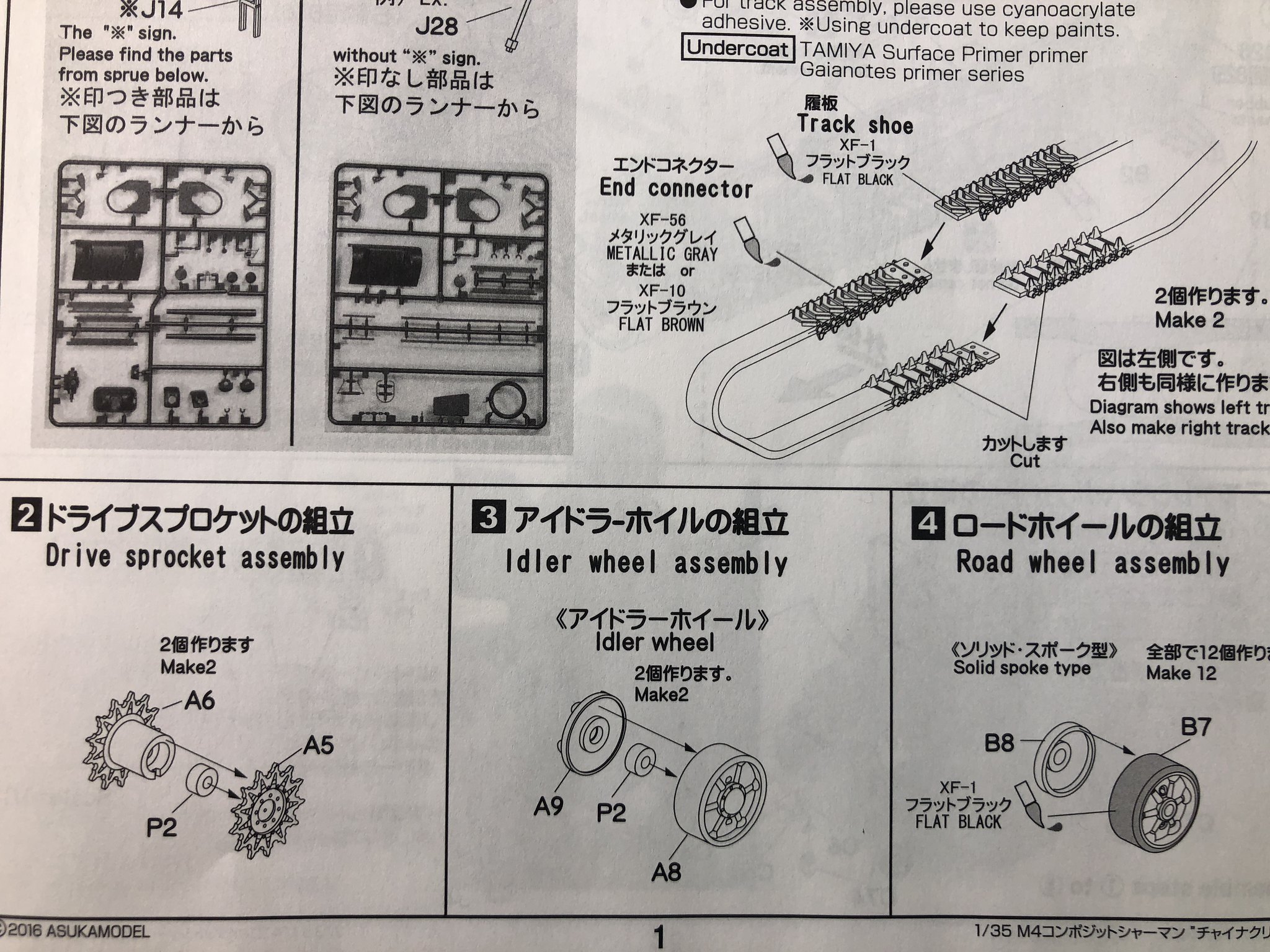
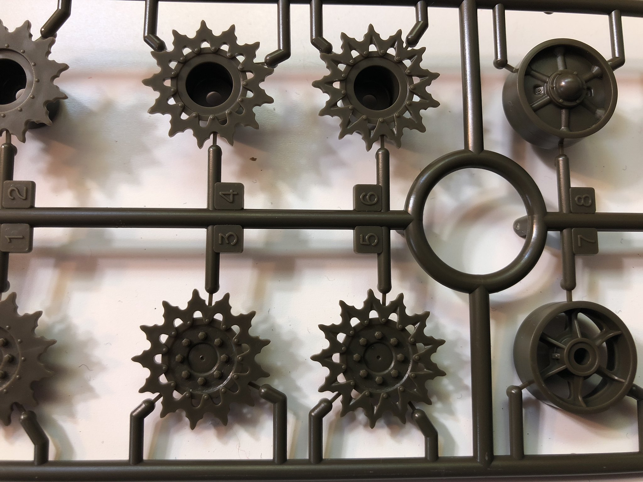
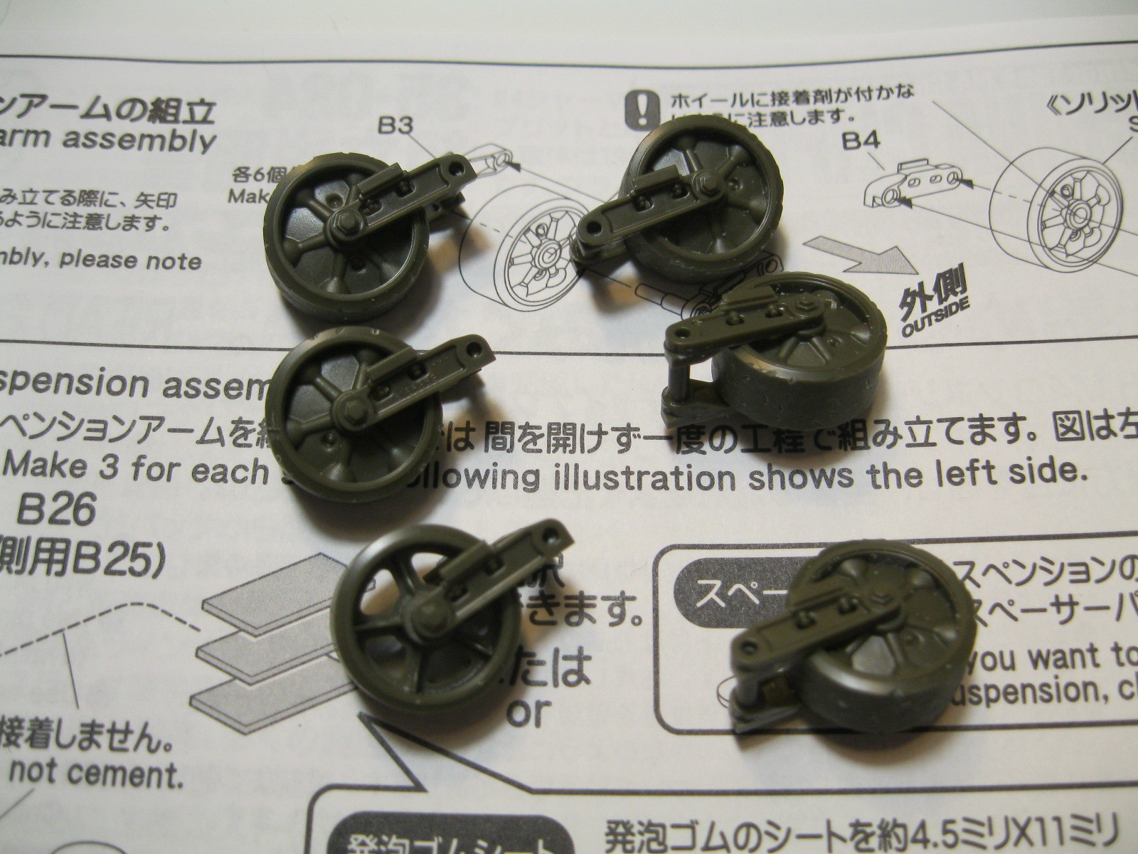
The kit parts look good but there is a bit of flash here and there, and a few small sink marks. I will take photos of the parts as I build so no general overview. The first steps are assembly of the two part rubber tracks, which I am leaving for last, and assembly of the drive sprockets, idler and road wheels. The drive sprocket has very fine attachment points that sit on the inside face of the sprocket, making for very easy and clean removal. A small nylon washer is included and goes inside, same with the idlers. The idlers and road wheels are all slightly recessed down the mold seam. I carefully sanded them down even.

China clipper step 1 by russell amott, on Flickr
China Clipper fancy drive sprocket by russell amott, on Flickr
China clipper drive and idler by russell amott, on Flickr

Not a big start as of yet, but I am currently assembling the road wheels and bogies, which involves a bit of work. I will have more to post soon. If I missed anything let me know.
russamotto
Visit this Community
Utah, United States
Joined: December 14, 2007
KitMaker: 3,389 posts
Armorama: 2,054 posts
Posted: Wednesday, September 05, 2018 - 04:04 AM UTC
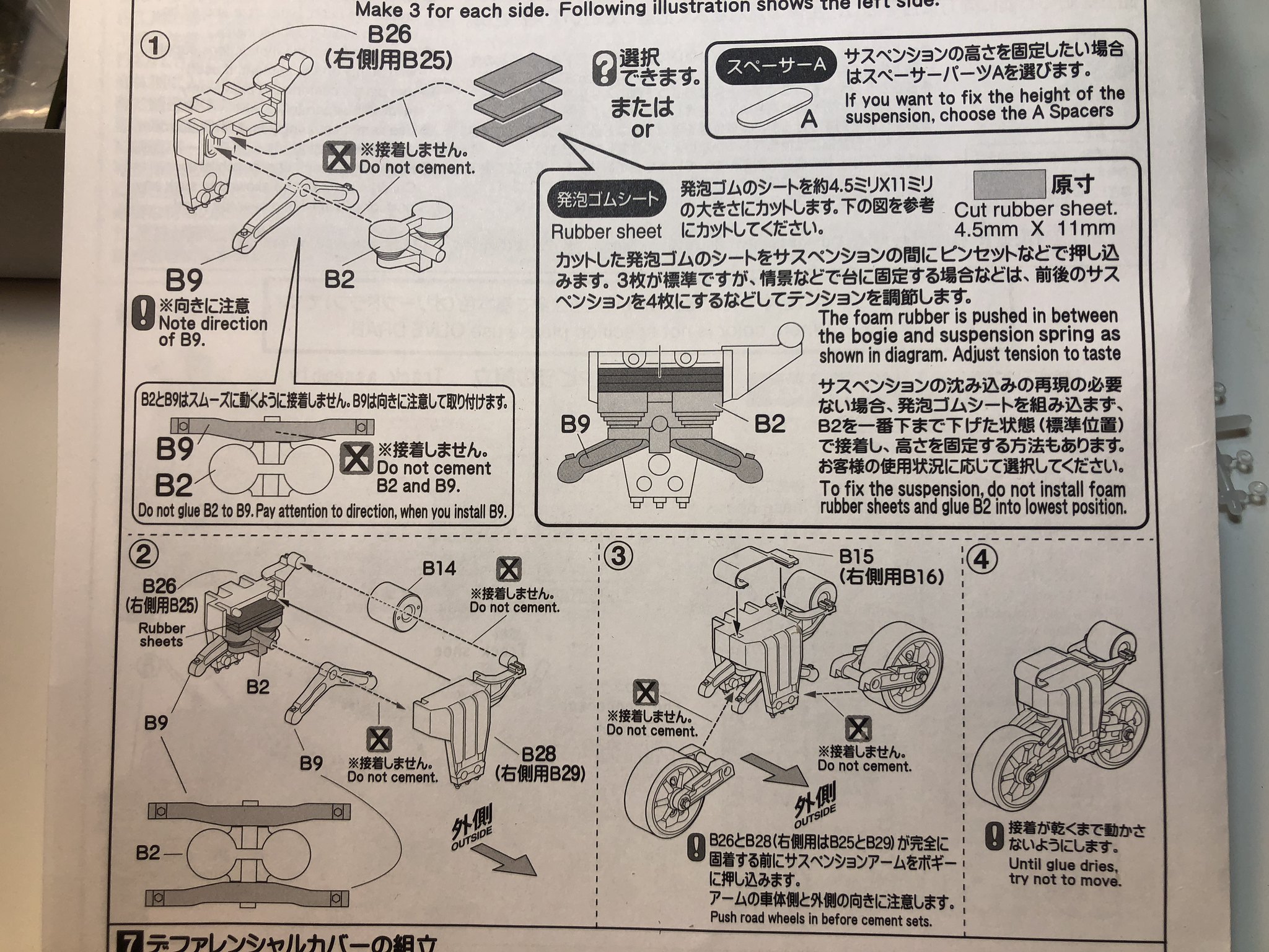
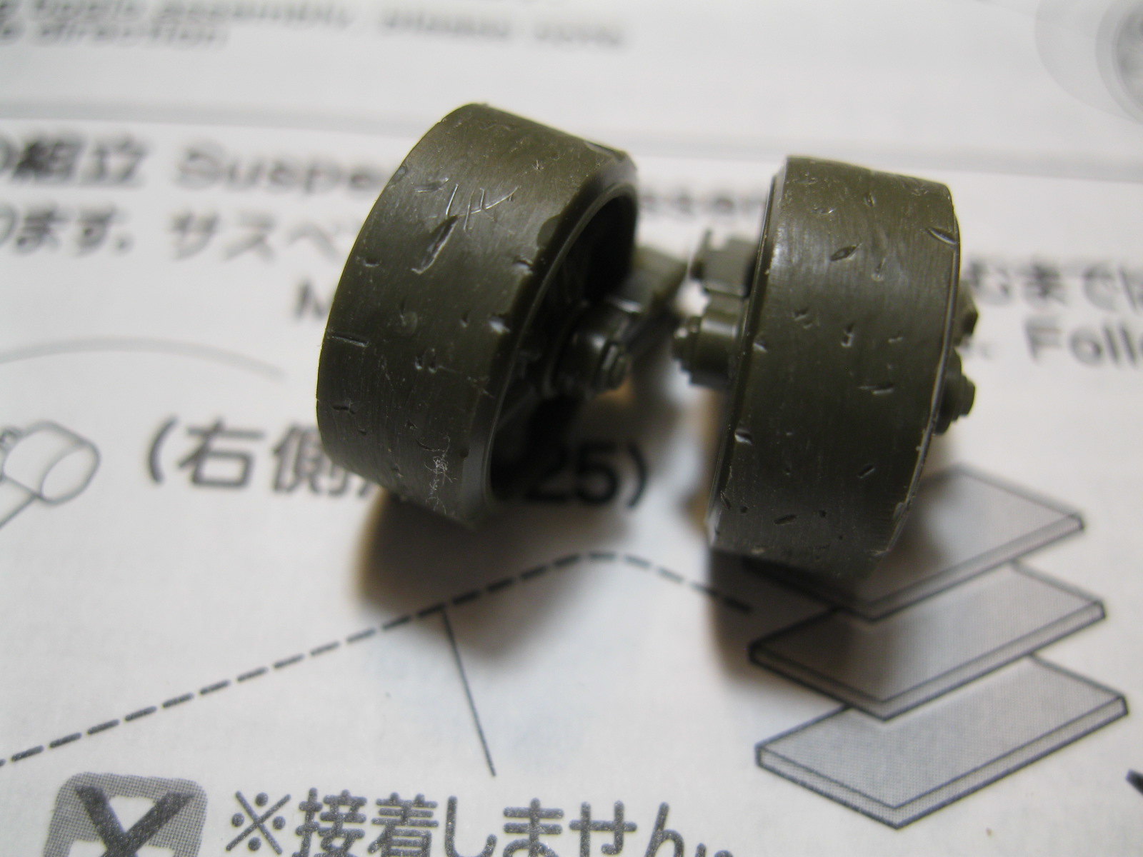
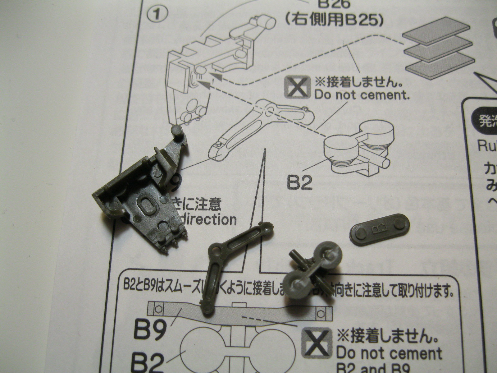
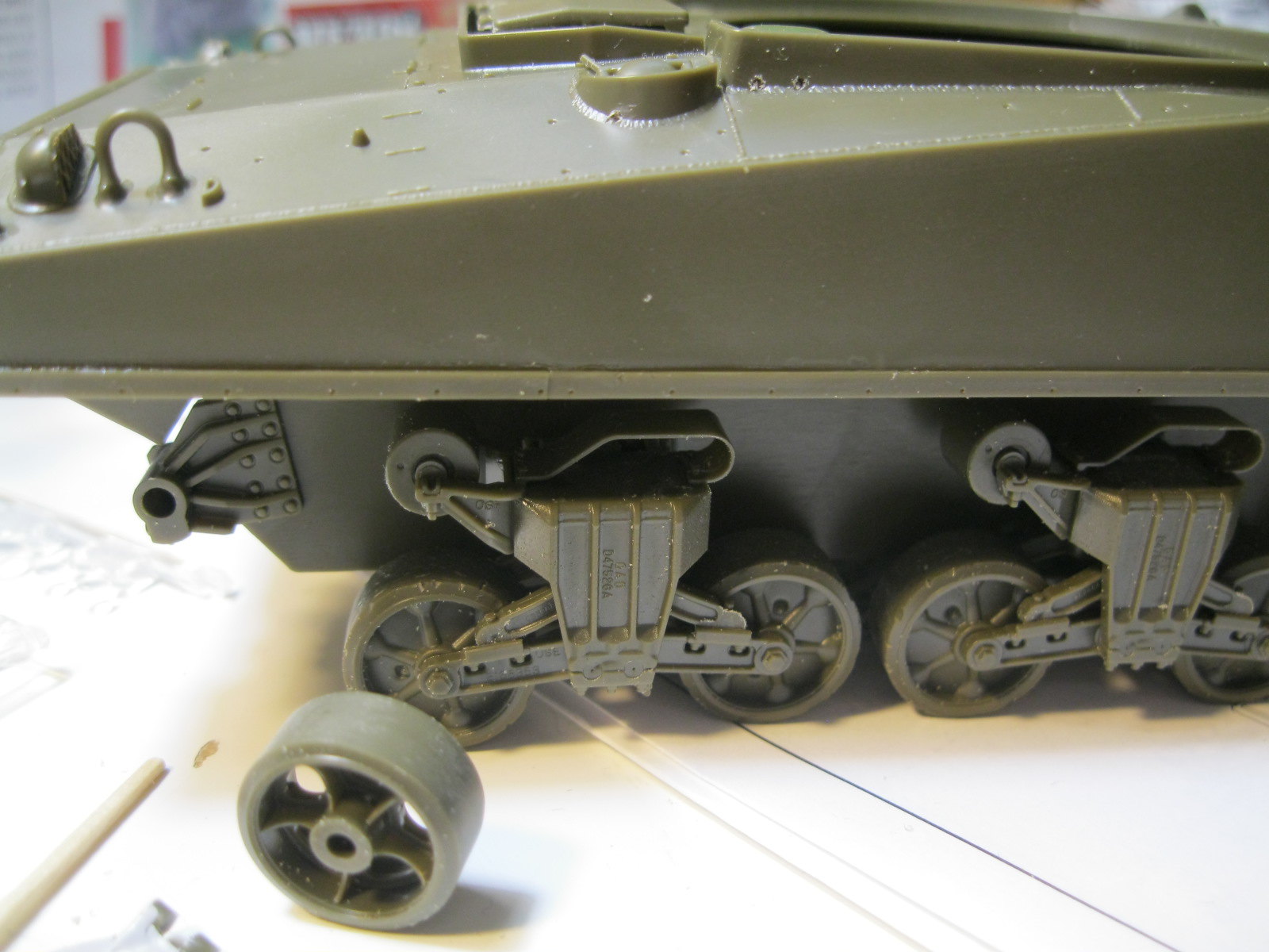
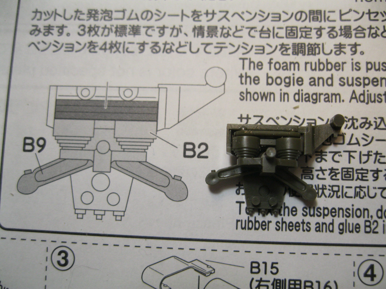
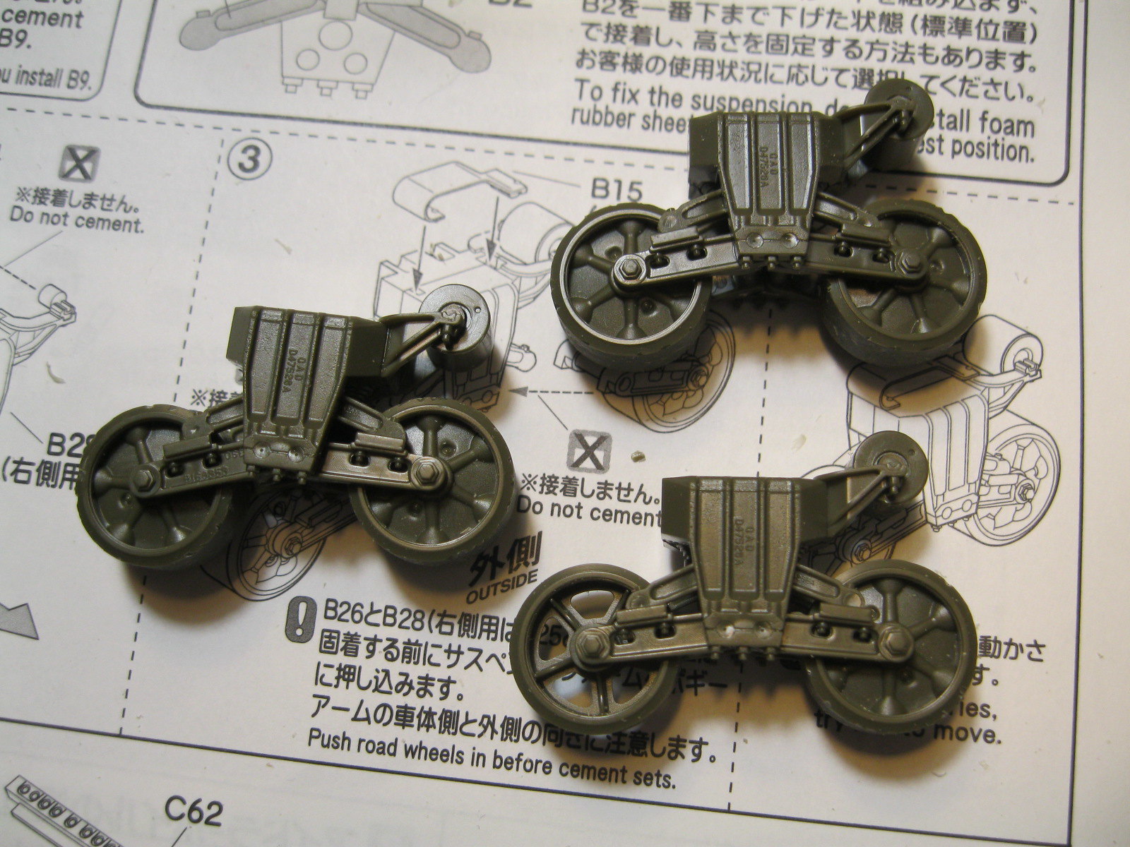
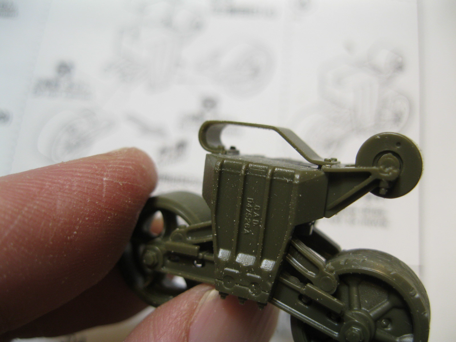
Each bogie assembly is made up of 16 parts, which takes some time to clean up and assemble. There is an option of using a foam insert inside that allows for some articulation and with careful assembly the road wheels will move freely. If you have the right track I assume you could push the completed tank around on the desk top or carpet, but the effort it would take would automatically depress the suspension so you would lose the vertical movement. You can push on it with your finger and watch it go up and down if so inclined, but I opted for the simple plastic insert. There are three sizes to set it at different levels. I went with the middle, B, which I thought would represent an operating tank at normal weight. I took the time to rough up the road wheels to make them look worn, but left the replacement wheels (open spoke) in better condition to show they were new.
Step 5 by russell amott, on Flickr
Step 6 by russell amott, on Flickr
IMG_9638 by russell amott, on Flickr
IMG_9639 by russell amott, on Flickr
IMG_9640 by russell amott, on Flickr
IMG_9641 by russell amott, on Flickr
IMG_9642 by russell amott, on Flickr
IMG_9643 by russell amott, on Flickr

The return skid (can't remember what it is called right now) includes one bolt head on the inside, but needs the inner bolt added if you want. I removed the bolt heads from the early skids which are included in the kit. All the parts go on well but the mating faces are sunken and need a bit of cleanup. For maximum detail each road wheel would need some rivet heads (included on the sprue) attached to the inner rim, four bolt heads on the inside of the raised roller arm and four small holes drilled on the other face of the bogie. If the kit is weathered as the tank appears in the actual photo, none of that will be visible at all.
IMG_9644 by russell amott, on Flickr
IMG_9645 by russell amott, on Flickr

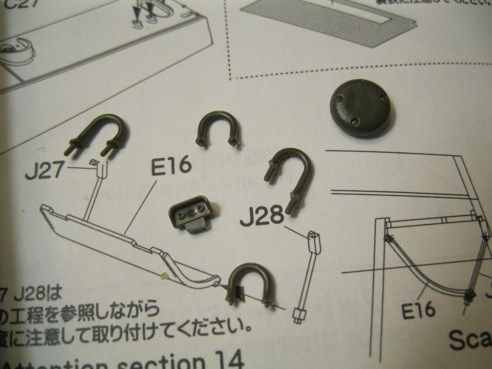
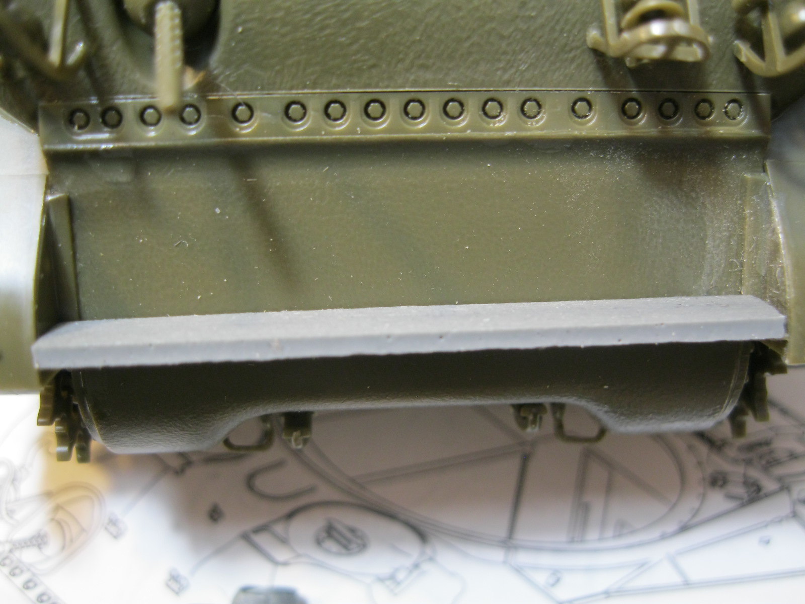
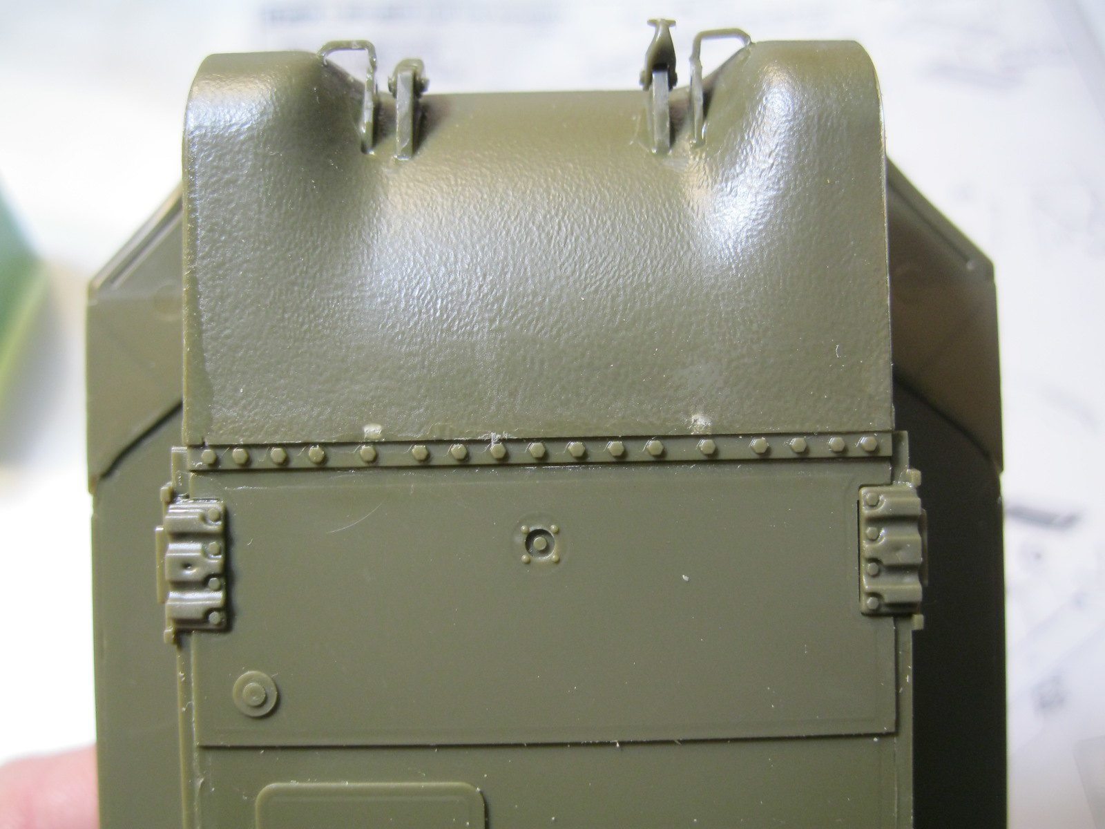
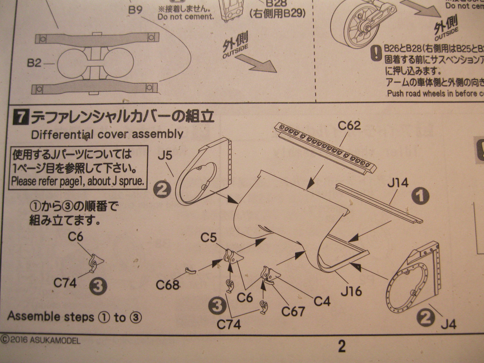
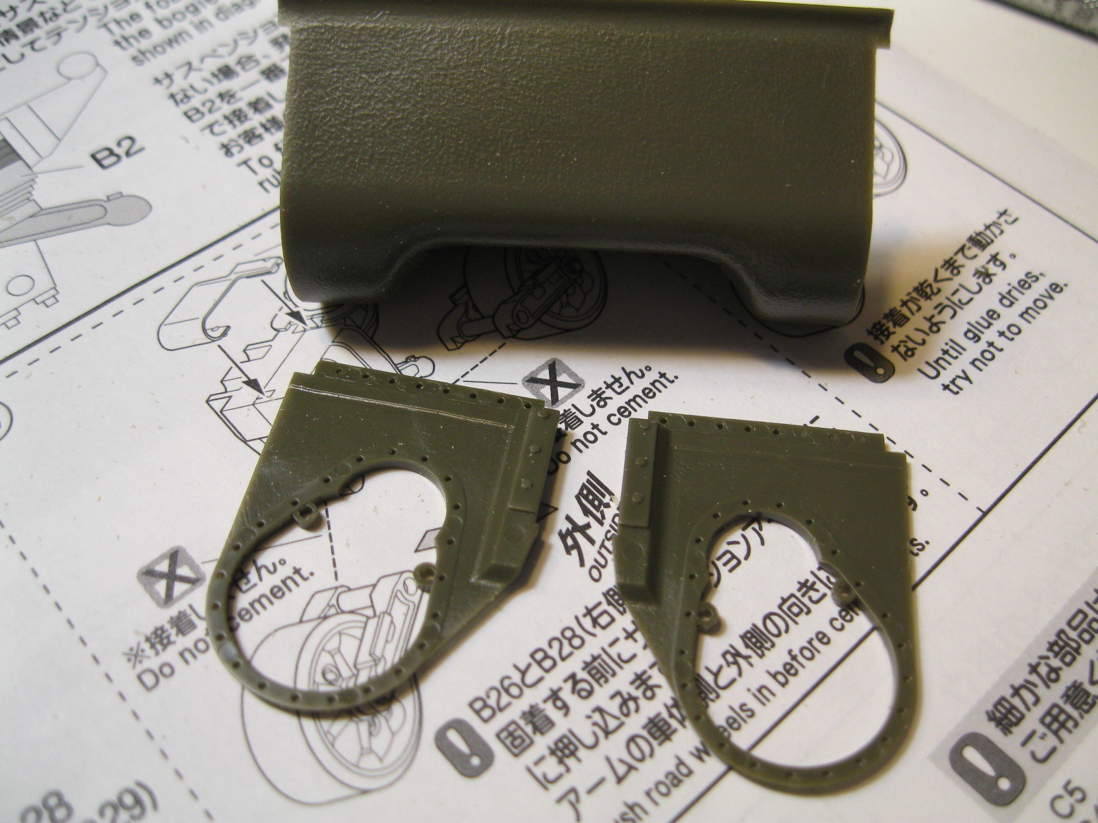
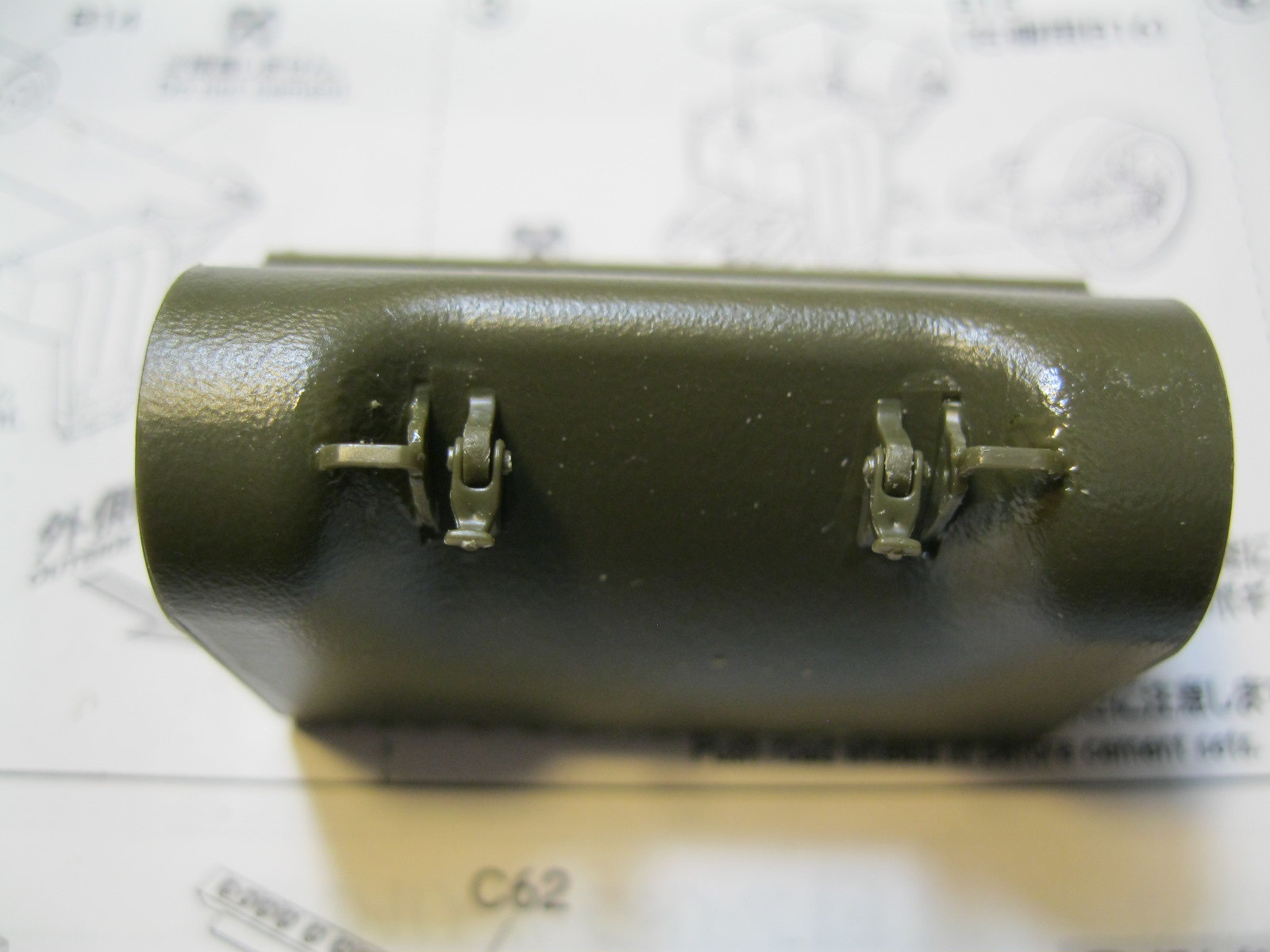
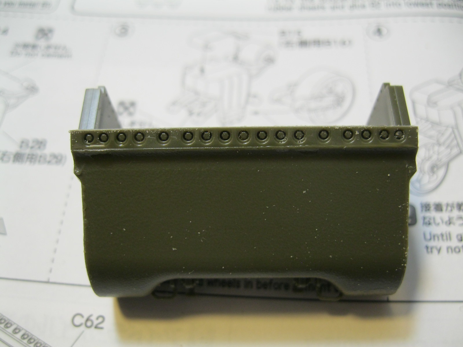
The transmission cover has a nice cast texture, something the cast turret lacks almost entirely (more on that later) and bolt strips on both the top and bottom edges. The outer towing eyes are handed and don't fill the mating slot completely so some putty will be needed. There is a 1:1 scale diagram showing the fitting of the welded step but it has the step too high. Using the box photos, actual photo and some careful trimming of the part got a better fit. Not perfect, but better.
IMG_9646 by russell amott, on Flickr
IMG_9647 by russell amott, on Flickr
IMG_9648 by russell amott, on Flickr
IMG_9649 by russell amott, on Flickr
IMG_9650 by russell amott, on Flickr

Next up will be construction of the lower hull.
TankManNick
Visit this Community
California, United States
Joined: February 01, 2010
KitMaker: 551 posts
Armorama: 543 posts
Posted: Wednesday, September 05, 2018 - 06:26 AM UTC

Quoted Text

Here is the box. I don't mind Asuka showing a built kit as it gives a good idea of how it should come out, but it comes off very shiny and toy like.


I believe it is representing a tank after a rainstorm. The top surfaces are drying out and the lower areas still seem wet. It is a hard look to pull off because armor modelers 'hate the shine' and want a dead-matt finish! Some guys in rain gear would help I guess.
russamotto
Visit this Community
Utah, United States
Joined: December 14, 2007
KitMaker: 3,389 posts
Armorama: 2,054 posts
Posted: Thursday, September 06, 2018 - 06:38 AM UTC
Thanks, Nick. It must have been raining when the photo of China Clipper was taken, based on all the mud. Makes me wonder how there is any soil left in France because you would think it was all carried away on tanks.

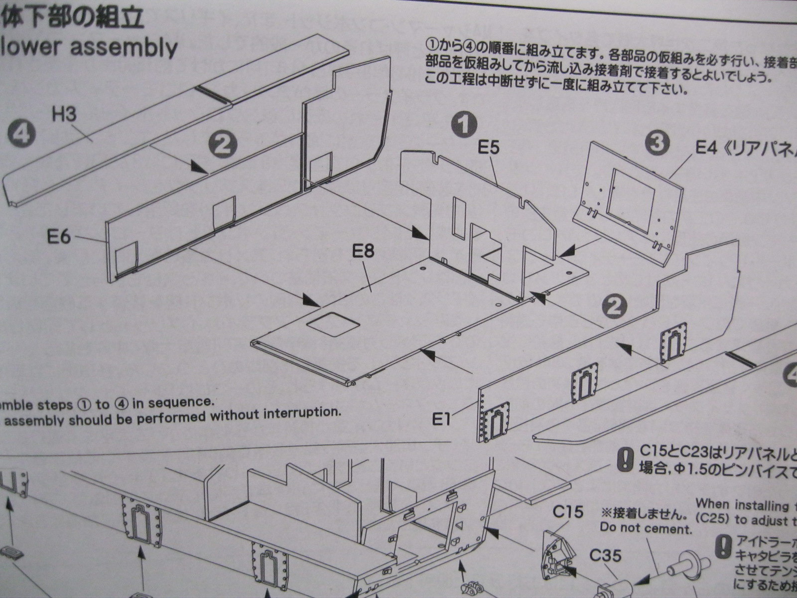
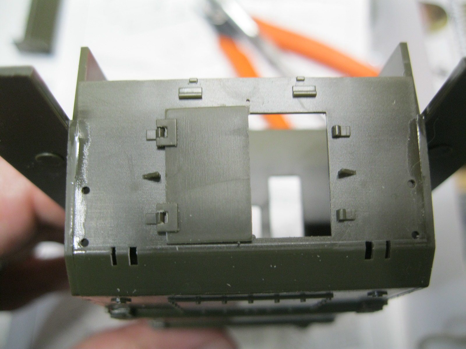
Bigger update today. Starting with the lower hull, I pulled out a small square to make sure everything was lined up properly. The hull parts fit well but are noticeably thinner than the typical molded hull tub. Makes for a better scale effect. It also makes me envious of the guys building all the new German tanks with full interiors. Nothing to show here.
IMG_9651 by russell amott, on Flickr
IMG_9653 by russell amott, on Flickr
IMG_9655 by russell amott, on Flickr
IMG_9656 by russell amott, on Flickr
IMG_9657 by russell amott, on Flickr
IMG_9658 by russell amott, on Flickr

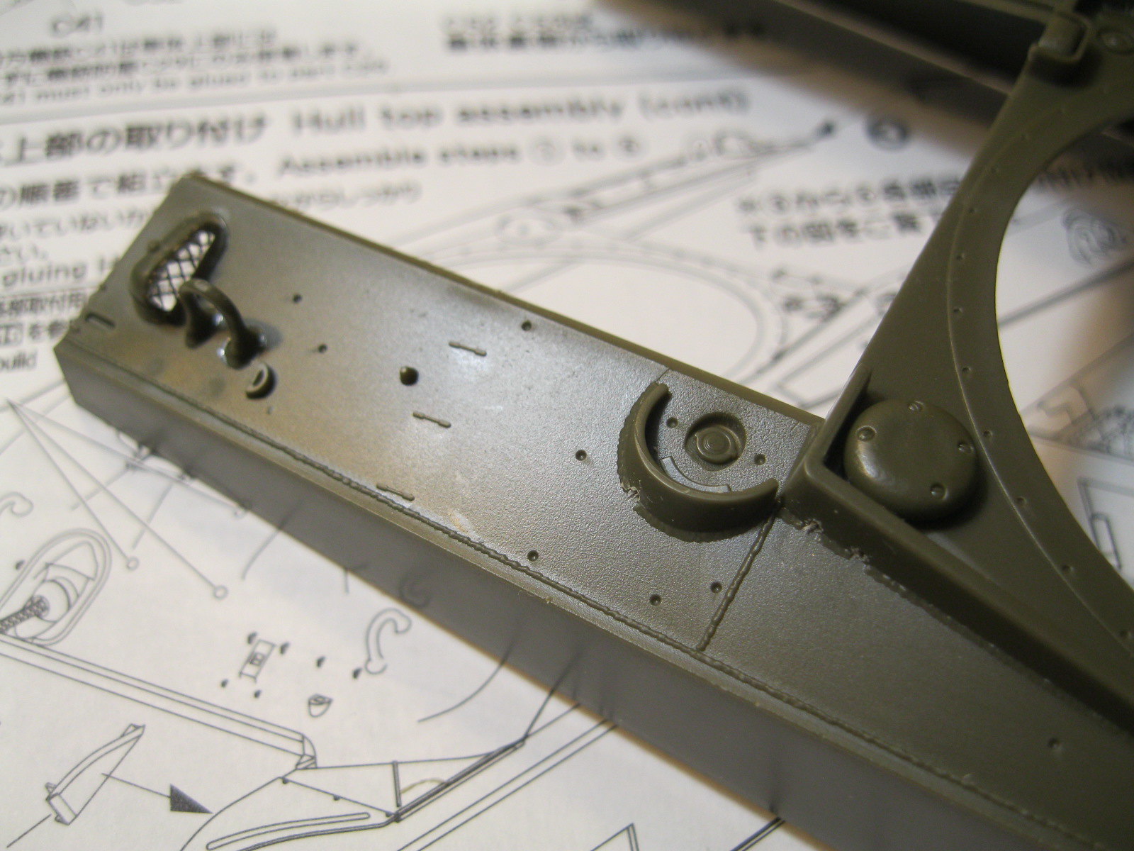
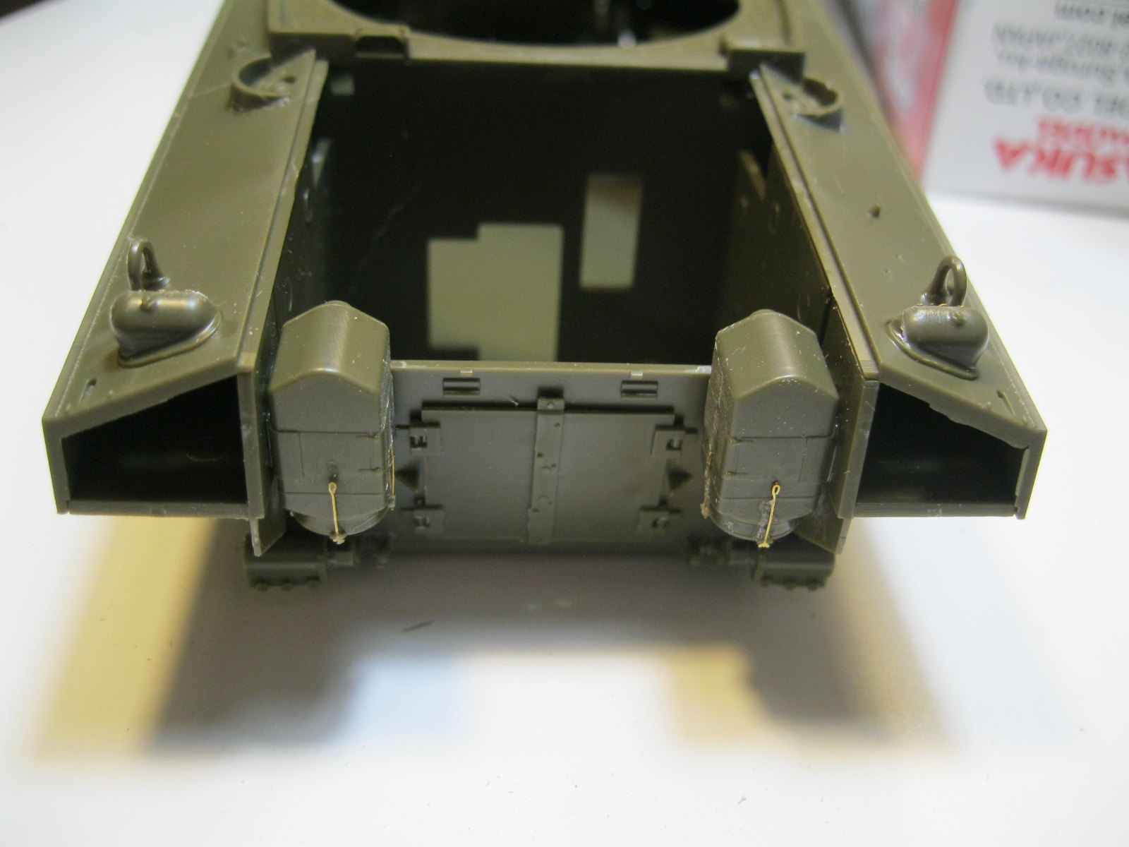
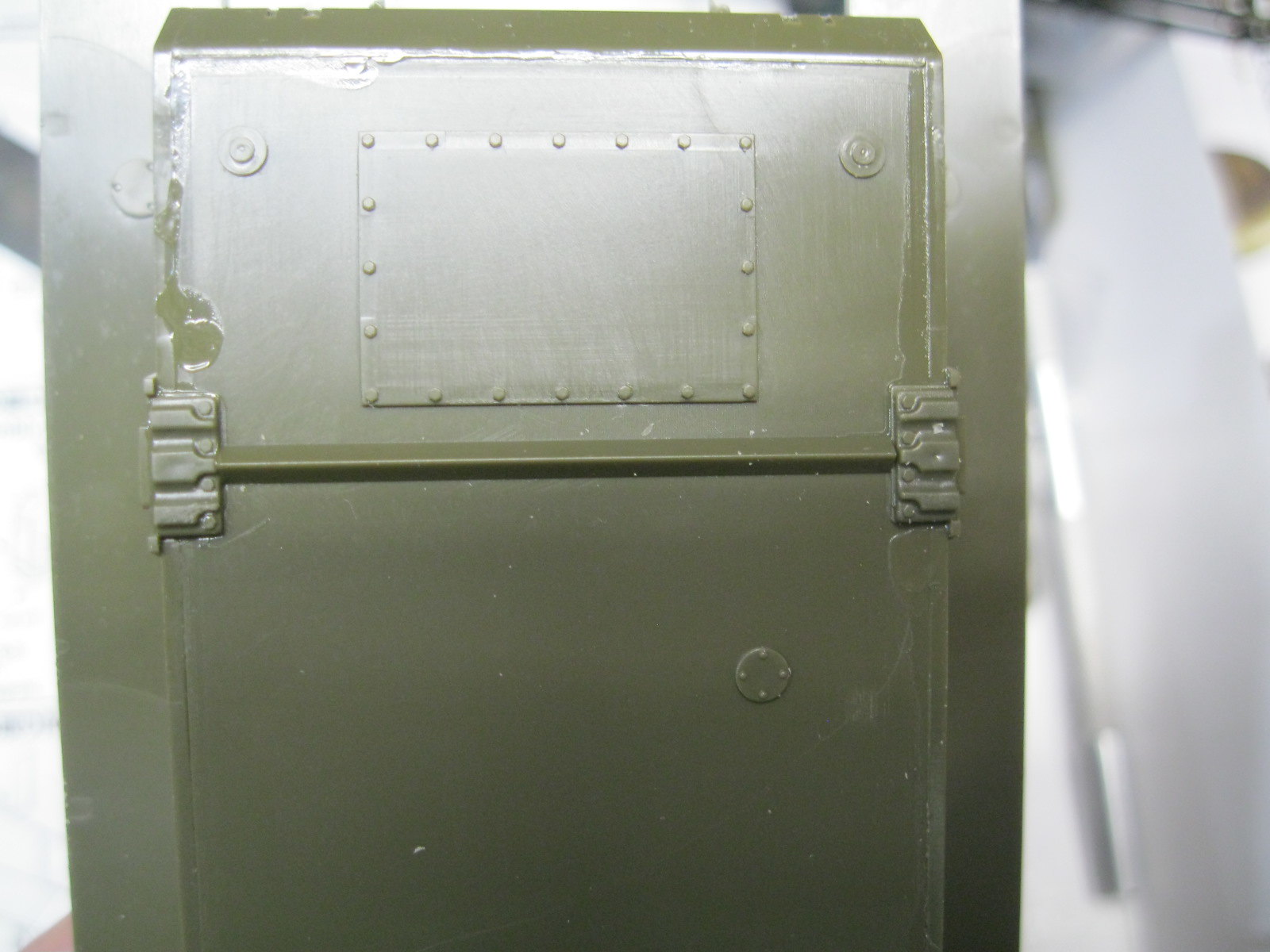
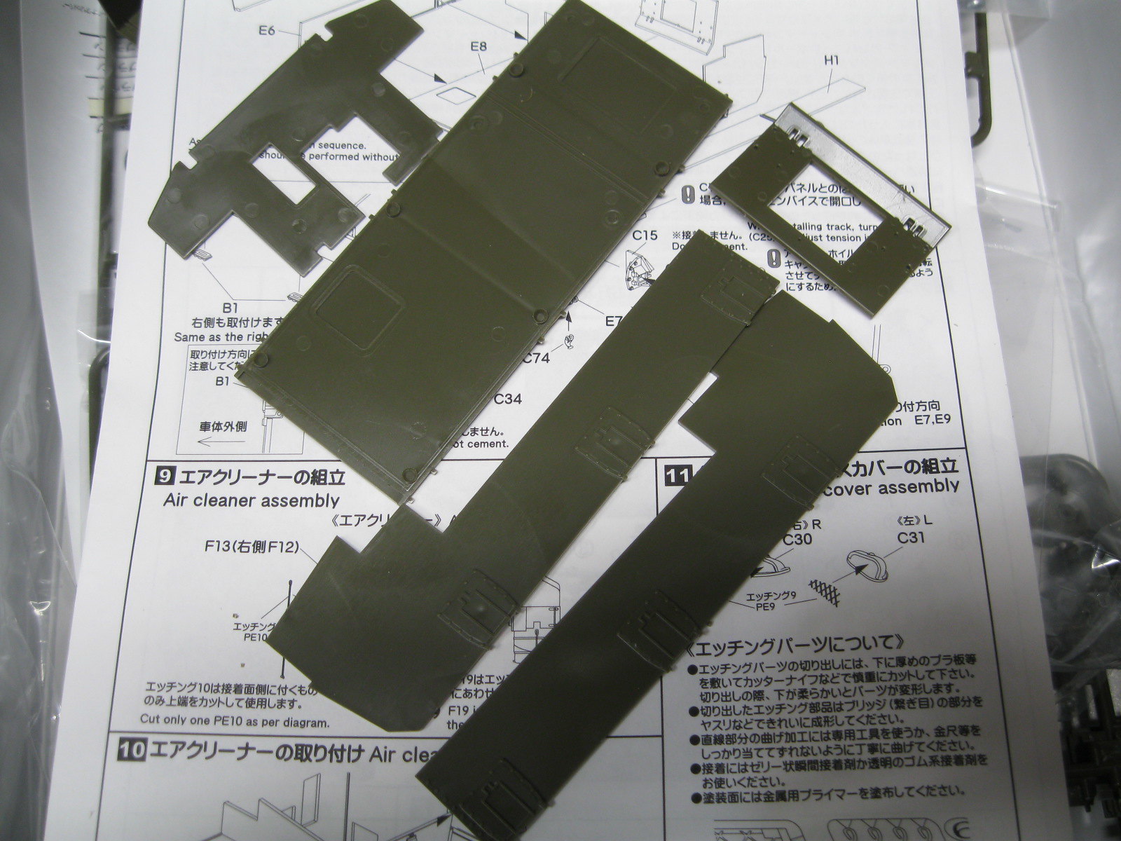
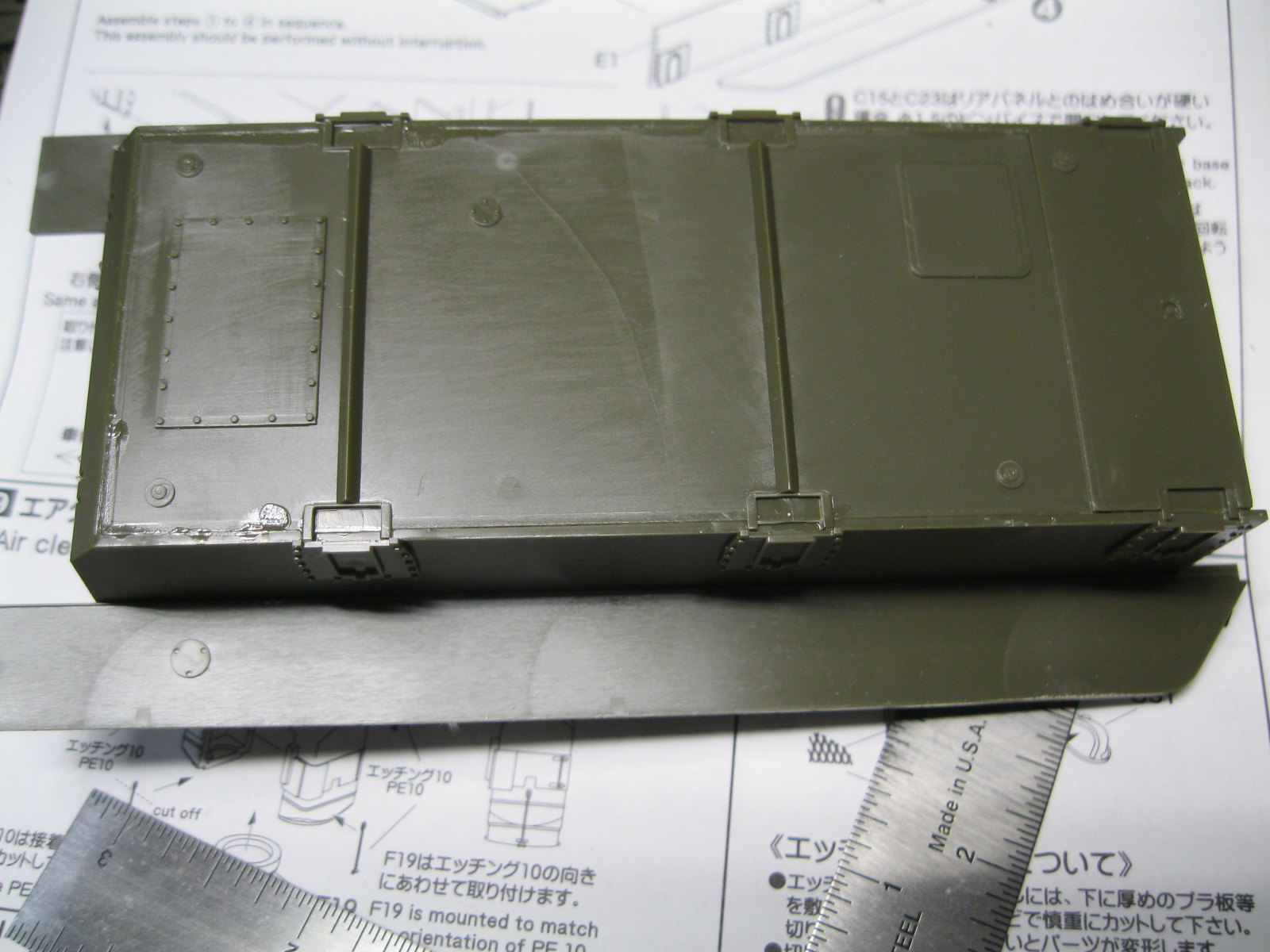
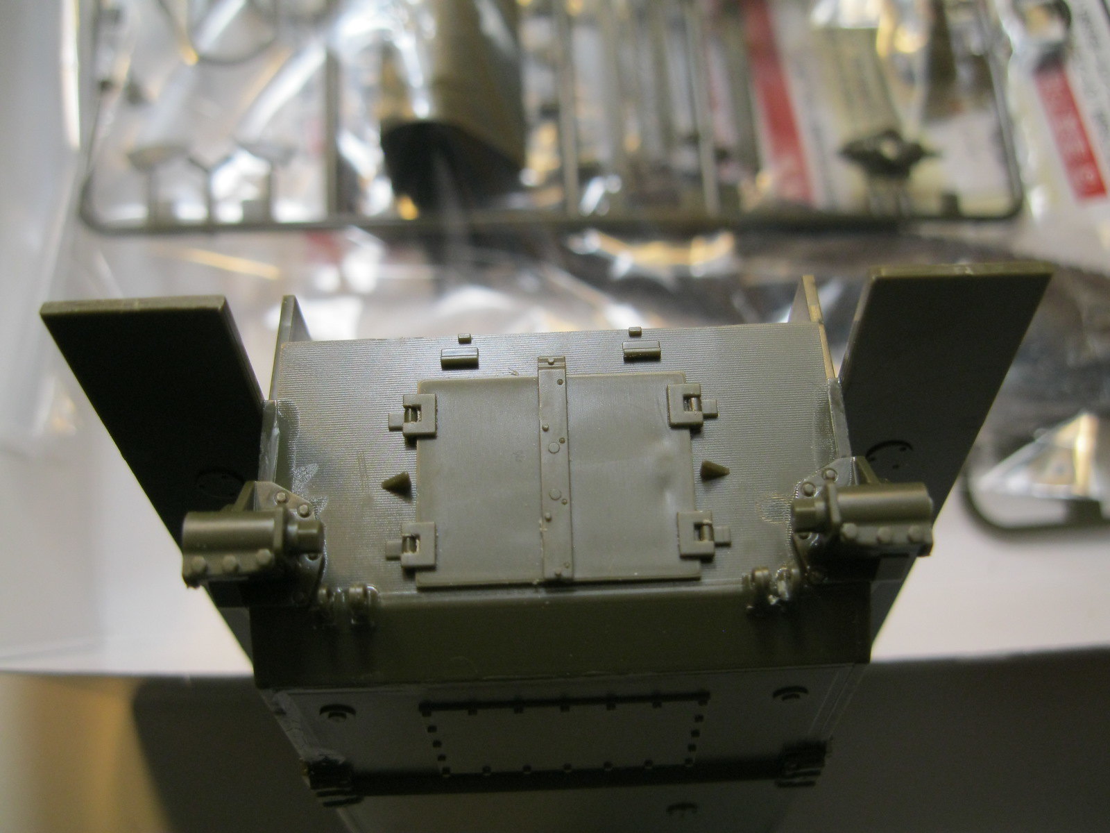
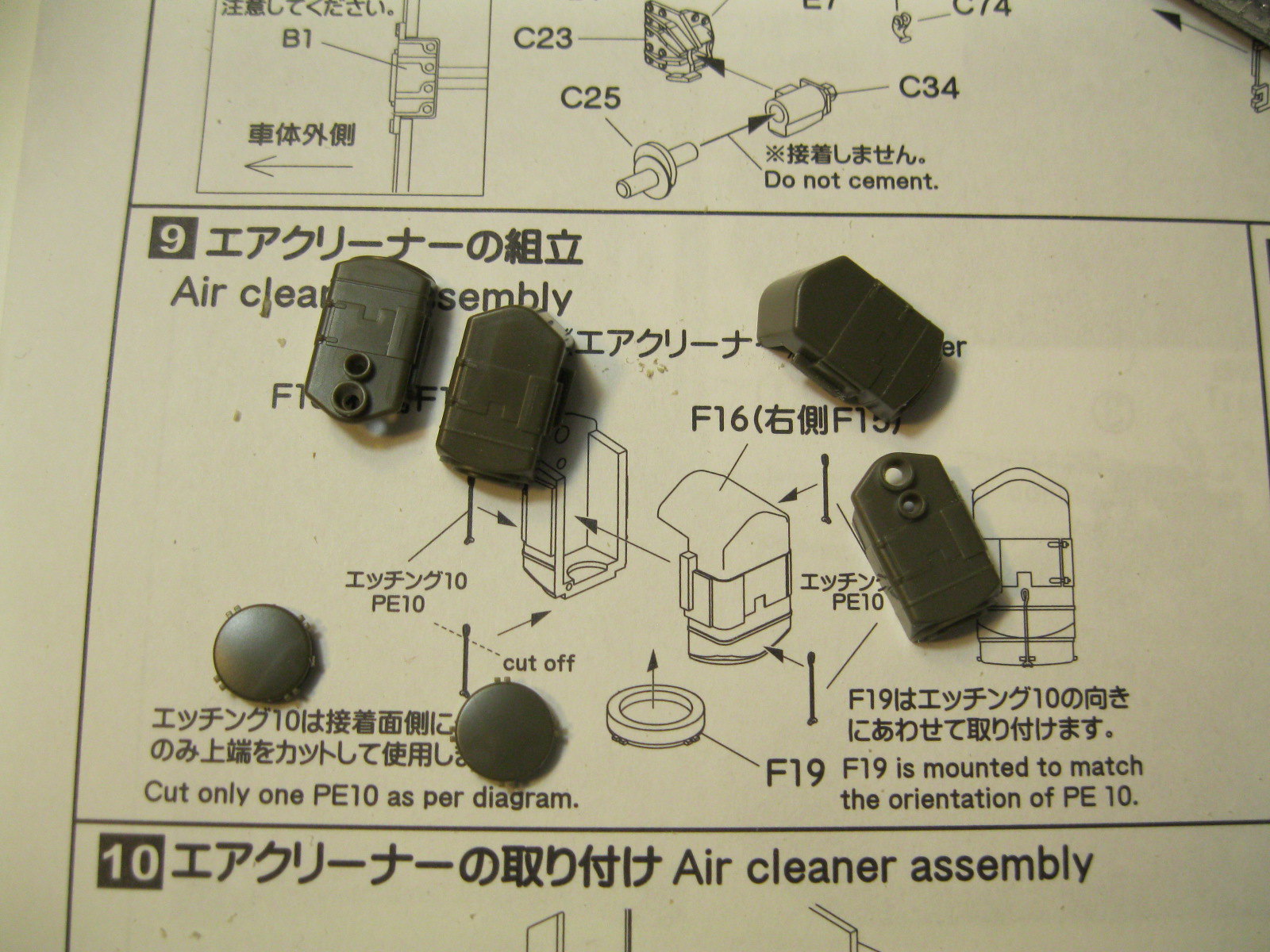
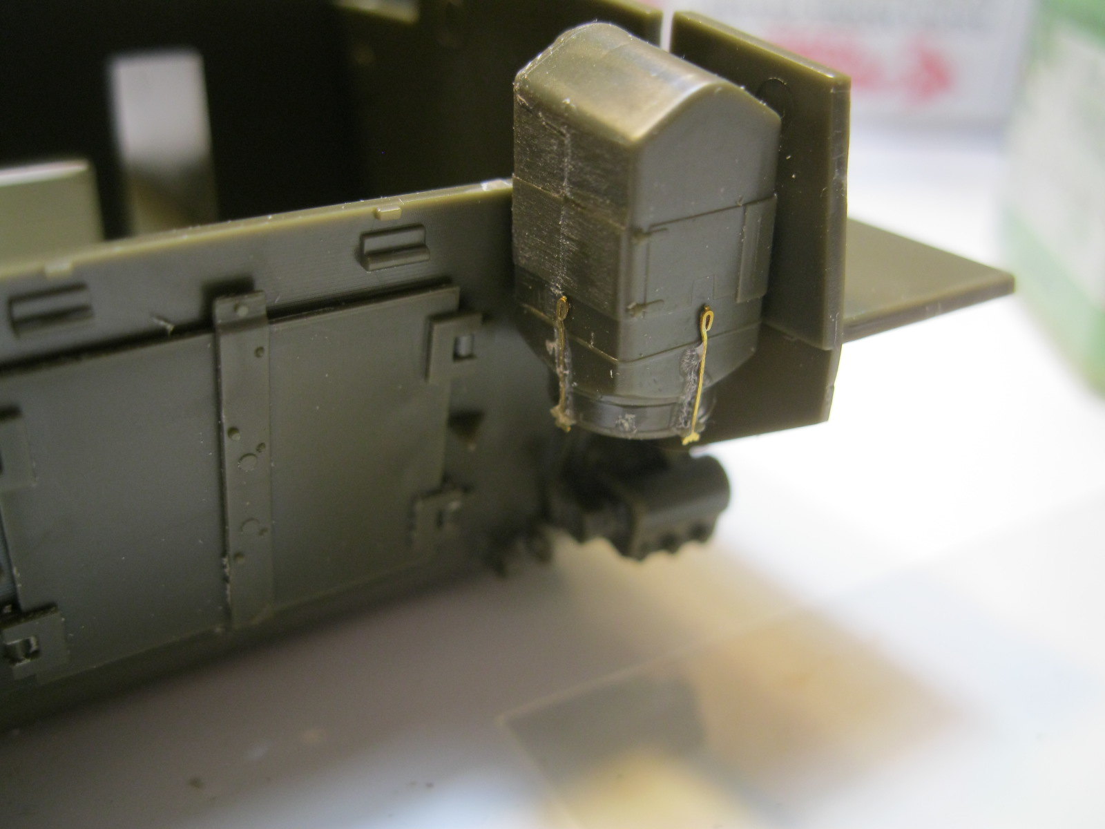
I didn't notice the lines across the rear plate until I was placing it. With the molded on details it isn't easy to clean up. I left it at this point, hoping that the added details will help cover it and no one will really be looking up the backside of the tank when it is done. Next came the placing of the small details on the rear and bottom. The engine access doors required some careful filing to get them to fit properly, something I remember from my previous Tasca kit. There are also some small sink marks visible on many of the little parts. Those on the hull bottom won't be seen. The air filters require some careful cleanup of the join seam and get small etch clamps. My CA glue was clumping and leaving little web strands so the clips look a little sloppy. I tossed that bottle and got a new one so the rest of the etch will go on cleanly.
IMG_9659 by russell amott, on Flickr
IMG_9660 by russell amott, on Flickr
IMG_9661 by russell amott, on Flickr
IMG_9662 by russell amott, on Flickr
IMG_9663 by russell amott, on Flickr
IMG_9664 by russell amott, on Flickr
IMG_9665 by russell amott, on Flickr

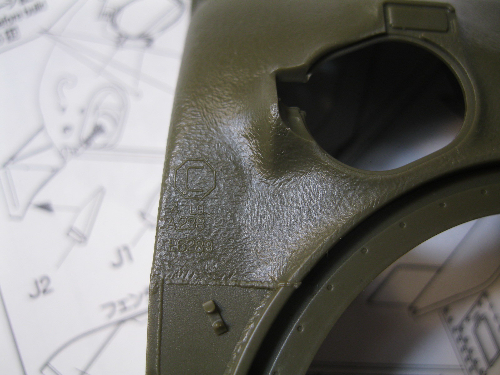
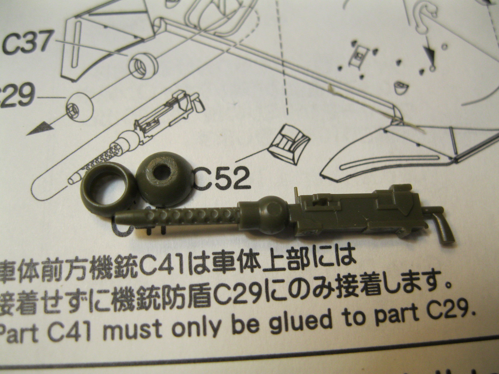
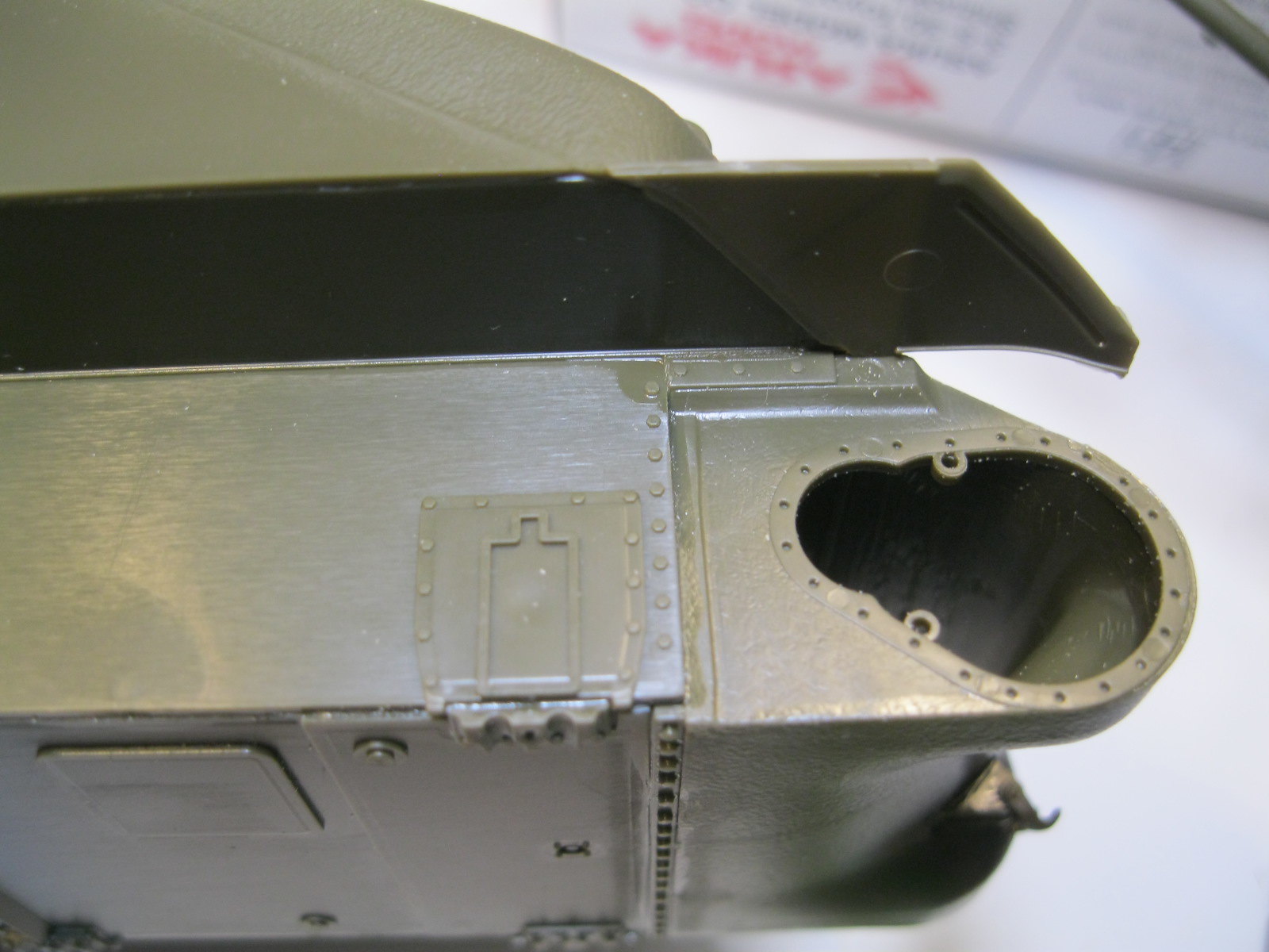
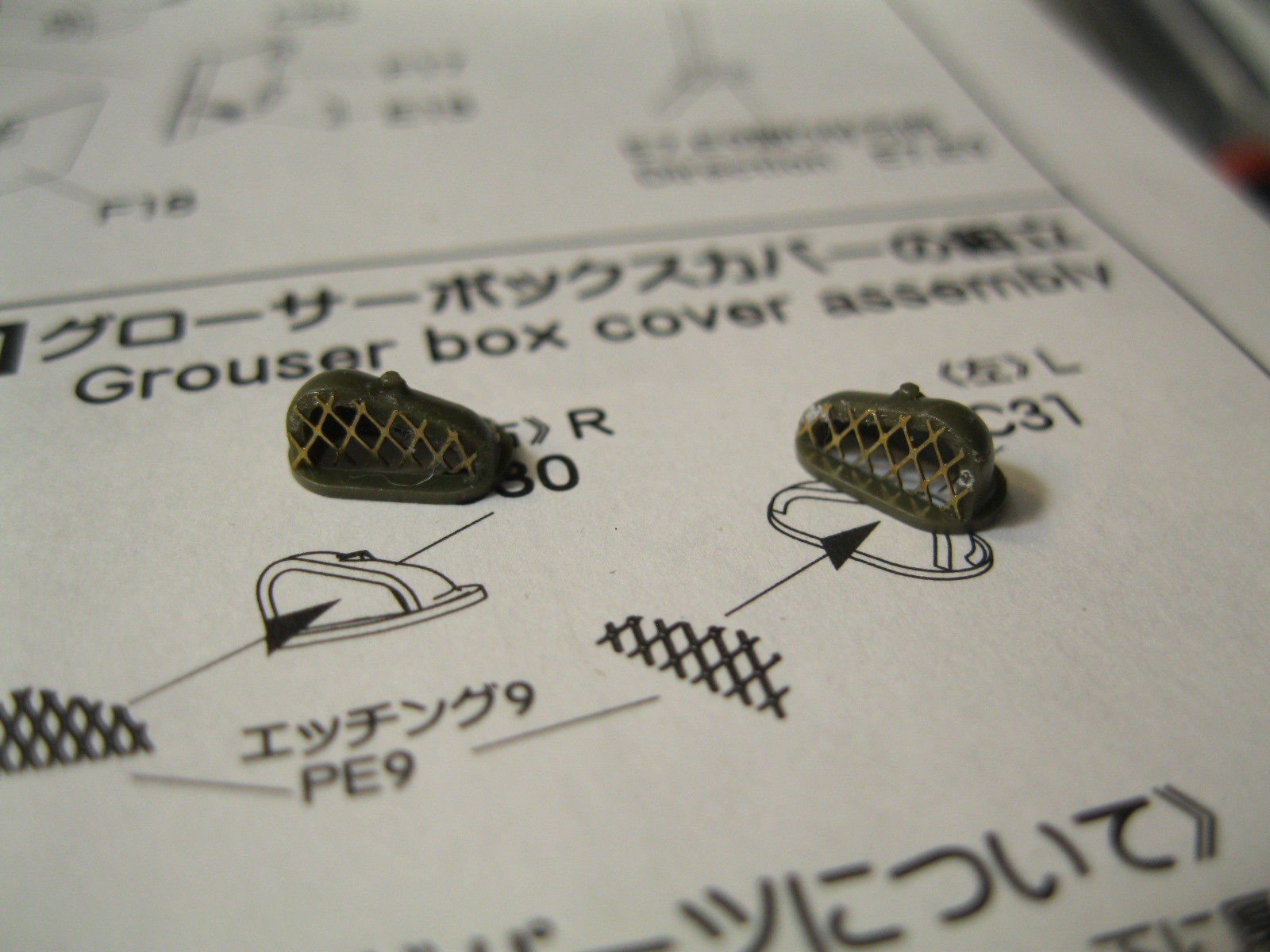
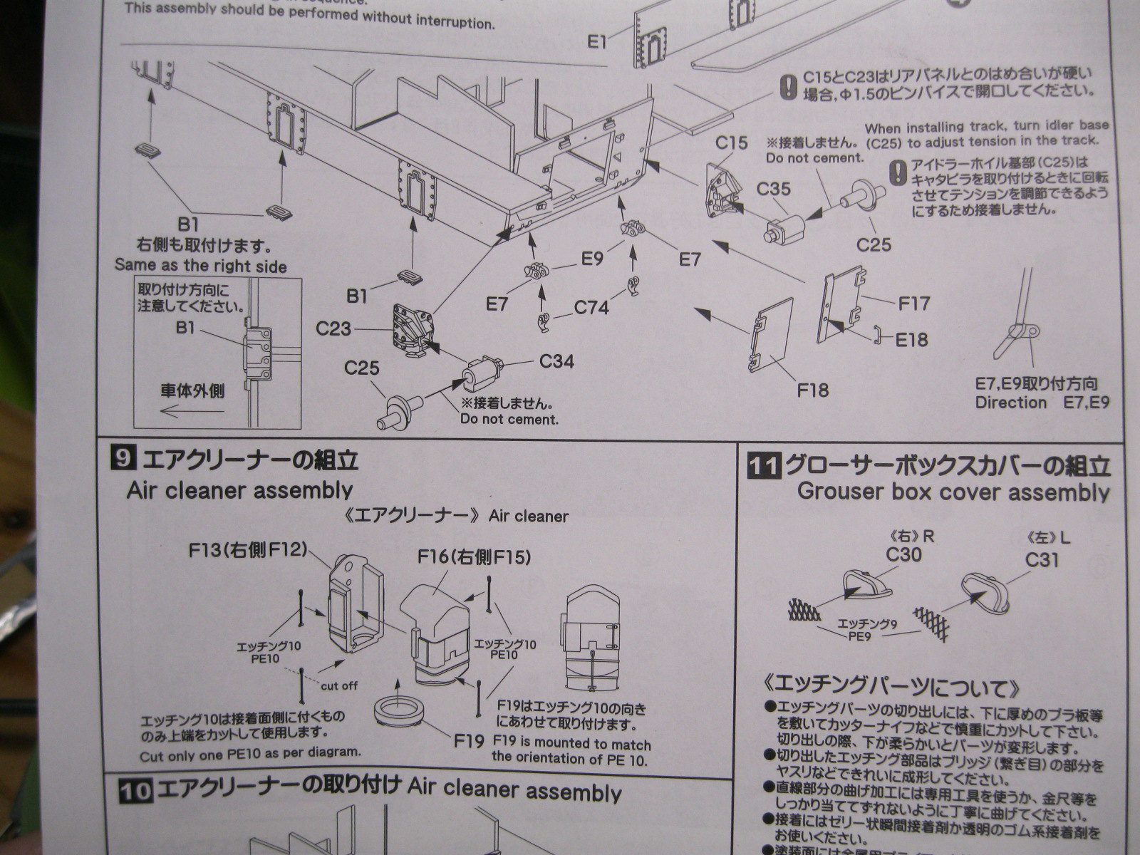
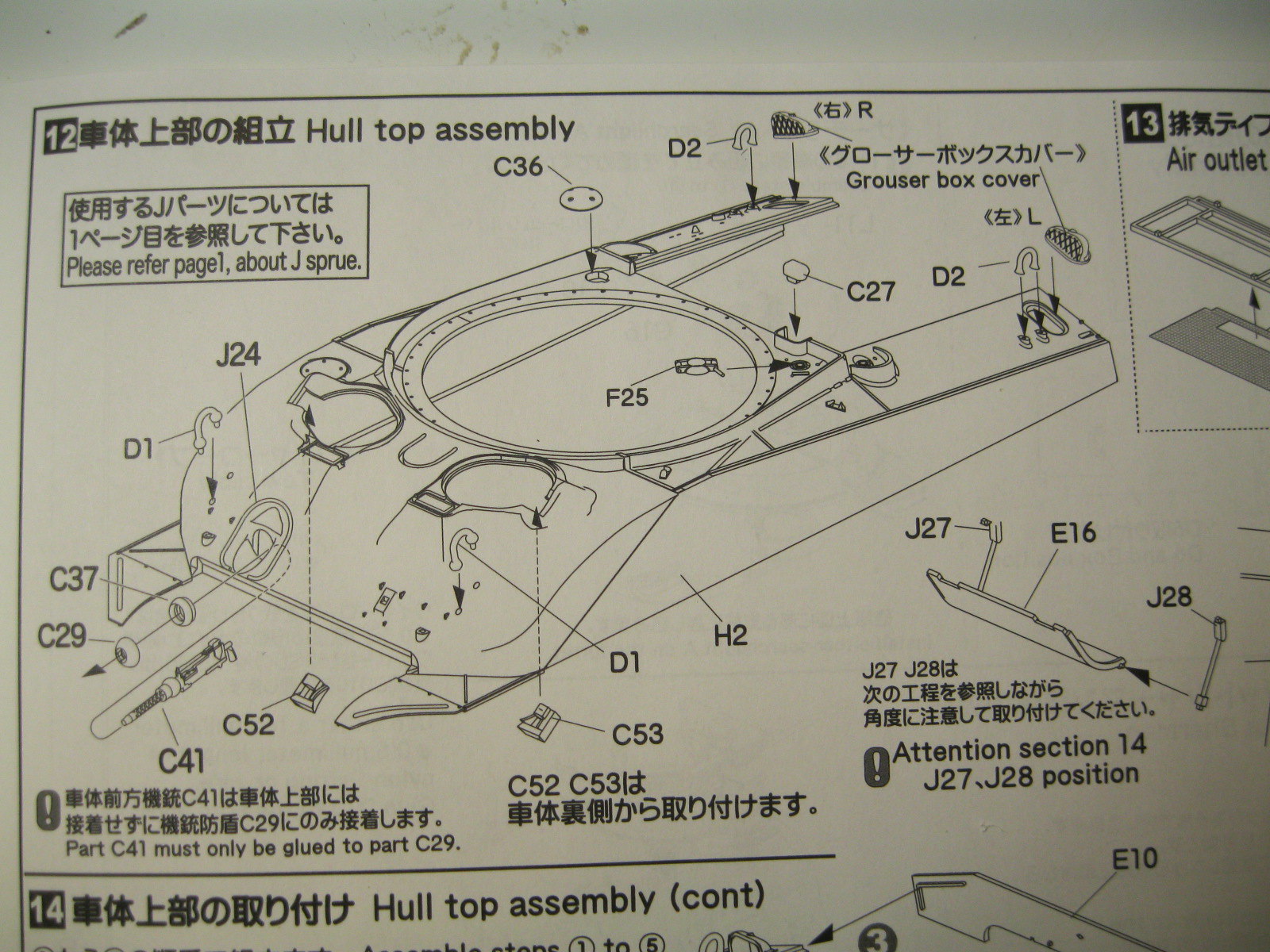
The grouser covers also get small etch screens. This is called out before the upper hull is shown but it will go right on, along with other small parts, so it is just a preparatory step. The hull is nicely done, with good casting texture on the front, a horizontal top edge where the side plates meet the engine deck and nice weld seam detail. There are small gaps in the weld bead around the turret and fuel cap splash guards for drain holes that you can add on your own. In comparing with the Dragon composite hull the only differences I can see are that the Dragon kit has softer contours around the hatches and includes the small bump on the glacis and the drain hole for the ventilator between the hatches. The foundry marks on the Tasca hull are facing opposite the Dragon marks. The Tasca kit includes a full, moveable hull MG, which I was happy to see just because it is there. German armor kits always have a highly detailed gun, even with no other interior. Allied kits usually just have a gun barrel that glues to the outside.
IMG_9666 by russell amott, on Flickr
IMG_9667 by russell amott, on Flickr
IMG_9668 by russell amott, on Flickr
IMG_9669 by russell amott, on Flickr
IMG_9670 by russell amott, on Flickr
IMG_9671 by russell amott, on Flickr
IMG_9672 by russell amott, on Flickr
IMG_9673 by russell amott, on Flickr
IMG_9674 by russell amott, on Flickr
IMG_9675 by russell amott, on Flickr
IMG_9677 by russell amott, on Flickr

At this point the upper and lower hull sections can be joined. For me it was easier to start with the differential housing and then place the upper hull. Test fitting showed a couple of areas that needed some careful filing to get a nice fit, and then everything was glued, working around the edges slowly. Of note, the instructions say to drill three holes in the glacis to place the brackets for the barrel lock. The travel lock isn't present in the photo of China Clipper, but the locking clip is and I suspect the foot mounts are under the stowage.
IMG_9680 by russell amott, on Flickr
IMG_9681 by russell amott, on Flickr
IMG_9682 by russell amott, on Flickr
IMG_9683 by russell amott, on Flickr
IMG_9684 by russell amott, on Flickr

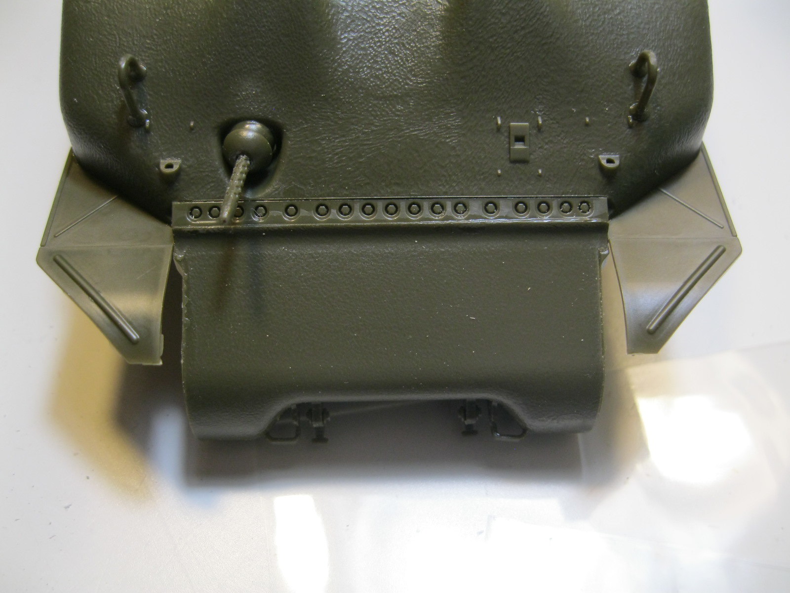
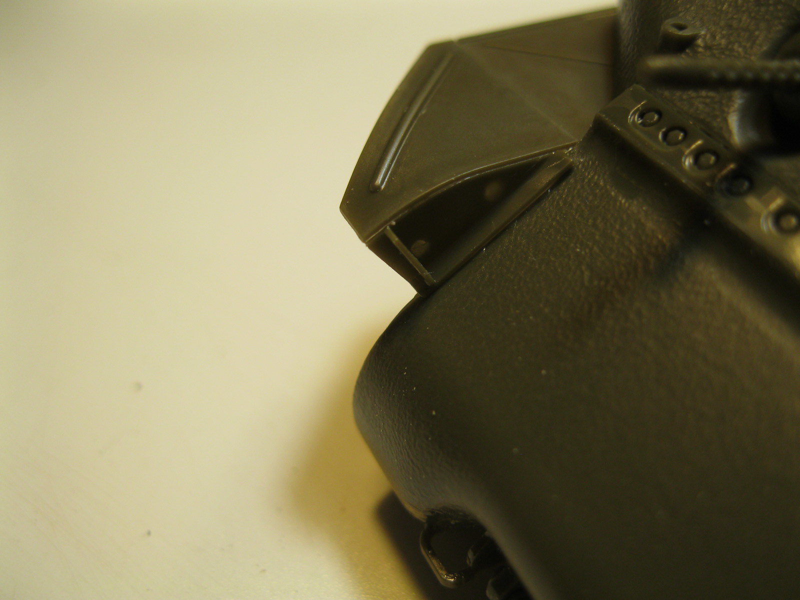
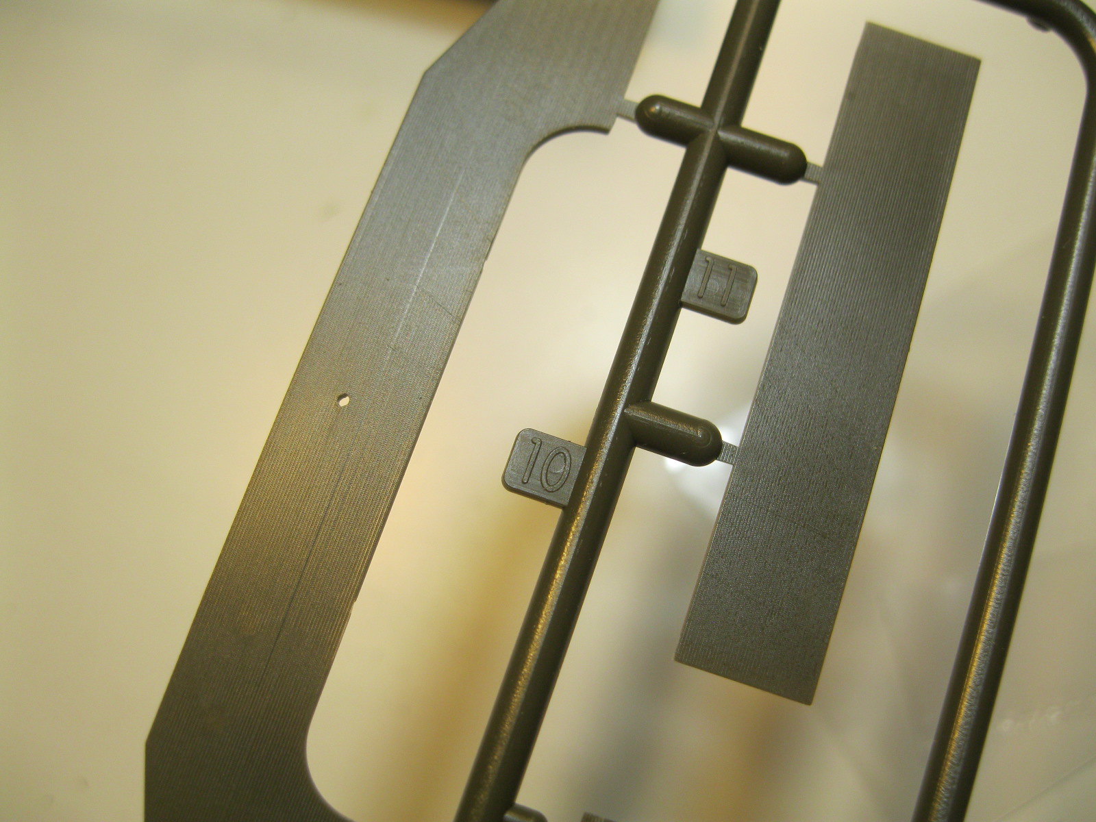
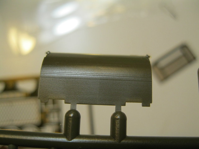
Next up is the exhaust deflector and rear plate. These parts also have the finely lined surface. I pulled out some steel wool and went over the parts carefully. The deflector is textured this way on the back surface. The front has three ejector pin marks that I worked to smooth out. The middle one received a dab of filler and was then smoothed. The etch screen rests on a plastic frame that has tiny attachment points. I placed the rear plate and then added these small details.
IMG_9678 by russell amott, on Flickr
IMG_9679 by russell amott, on Flickr
IMG_9685 by russell amott, on Flickr
IMG_9690 by russell amott, on Flickr
IMG_9691 by russell amott, on Flickr

I was just about to start on the hull hatches but was given a gentle reminder to take a break and play with someone.
IMG_9692 by russell amott, on Flickr
IMG_9695 by russell amott, on Flickr

That is all for now. After playtime I will get back to the hatches. I also did some texturing on the turret to give it time to set. Still lots of things to do but life has priorities.
russamotto
Visit this Community
Utah, United States
Joined: December 14, 2007
KitMaker: 3,389 posts
Armorama: 2,054 posts
Posted: Thursday, September 06, 2018 - 11:40 AM UTC
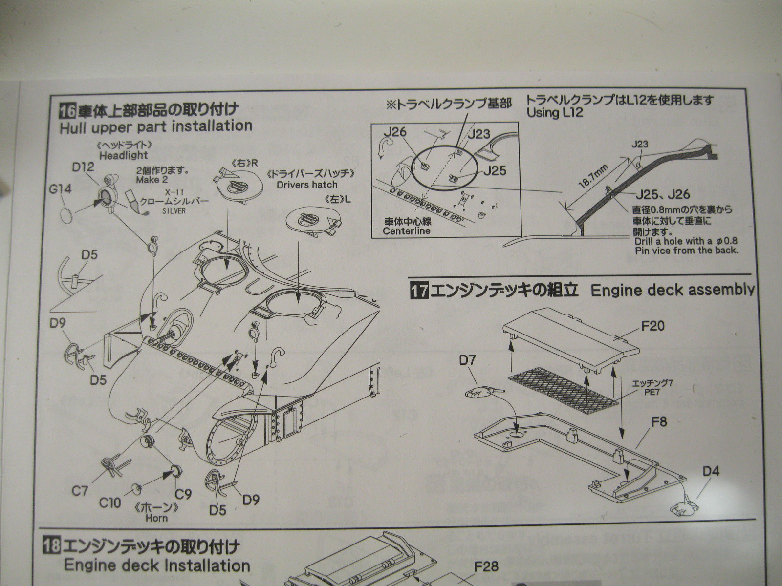
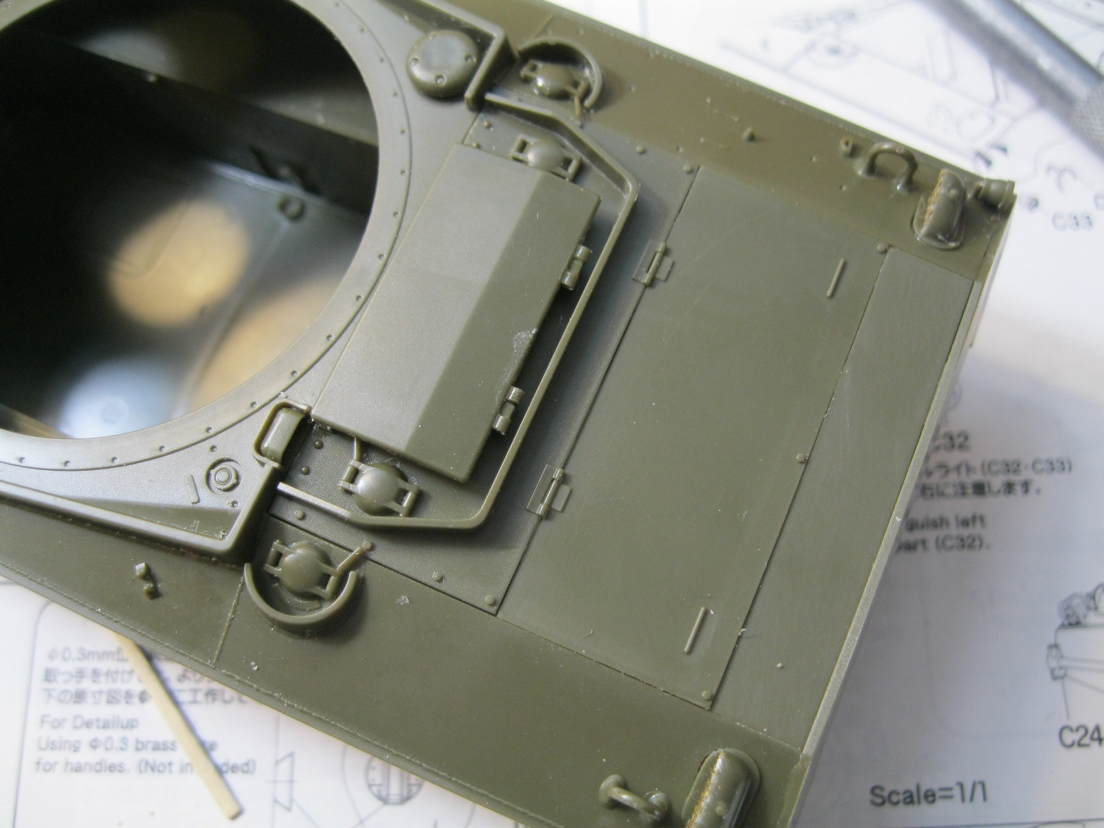
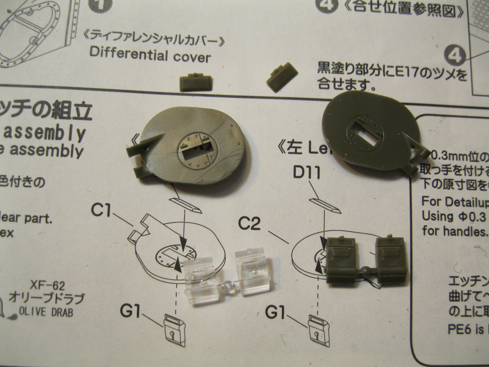
Finishing up the hull. I added the lights but left the brush guards off so I won't destroy them. The kit includes both etch and plastic brush guards. Also, the headlight lenses are offered in solid plastic and clear. I opted for the solid plastic as it appears in the photo they are painted out. The rear deck plates were carefully cleaned up and dry fitted to make sure everything fits. There is a nice etch screen under the access hatch. A small detail but according to Sherman Minutiae the handles on the middle plate should run parallel to the sides and not the rear.
IMG_9696 by russell amott, on Flickr
IMG_9697 by russell amott, on Flickr
IMG_9698 by russell amott, on Flickr
IMG_9699 by russell amott, on Flickr
IMG_9700 by russell amott, on Flickr
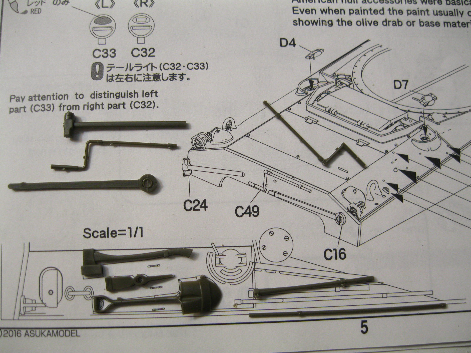
The various hand tools would be added at this point and there is a 1:1 scale template to guide in their positioning. I will wait until after painting to put them on. According to Sherman Minutiae the starter crank should not be the part shown but rather the one piece unit that is on a different sprue.
IMG_9701 by russell amott, on Flickr
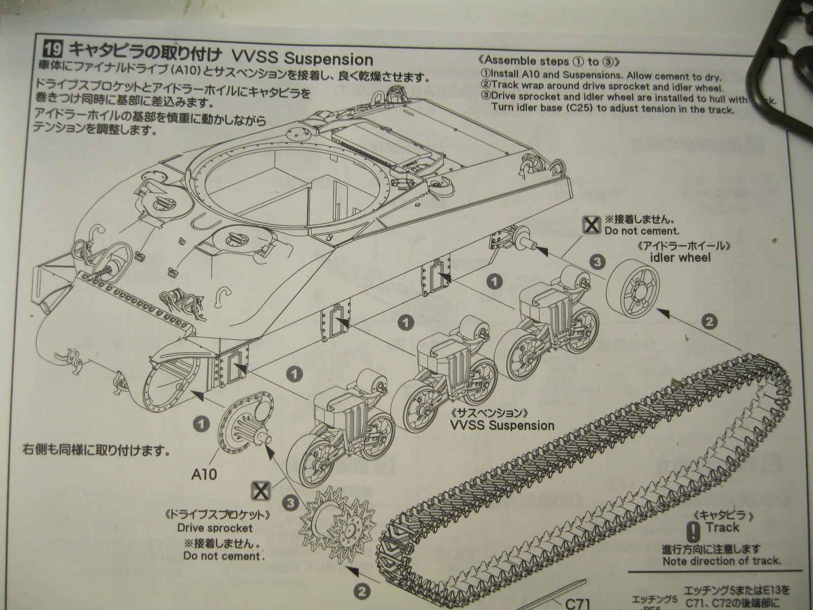
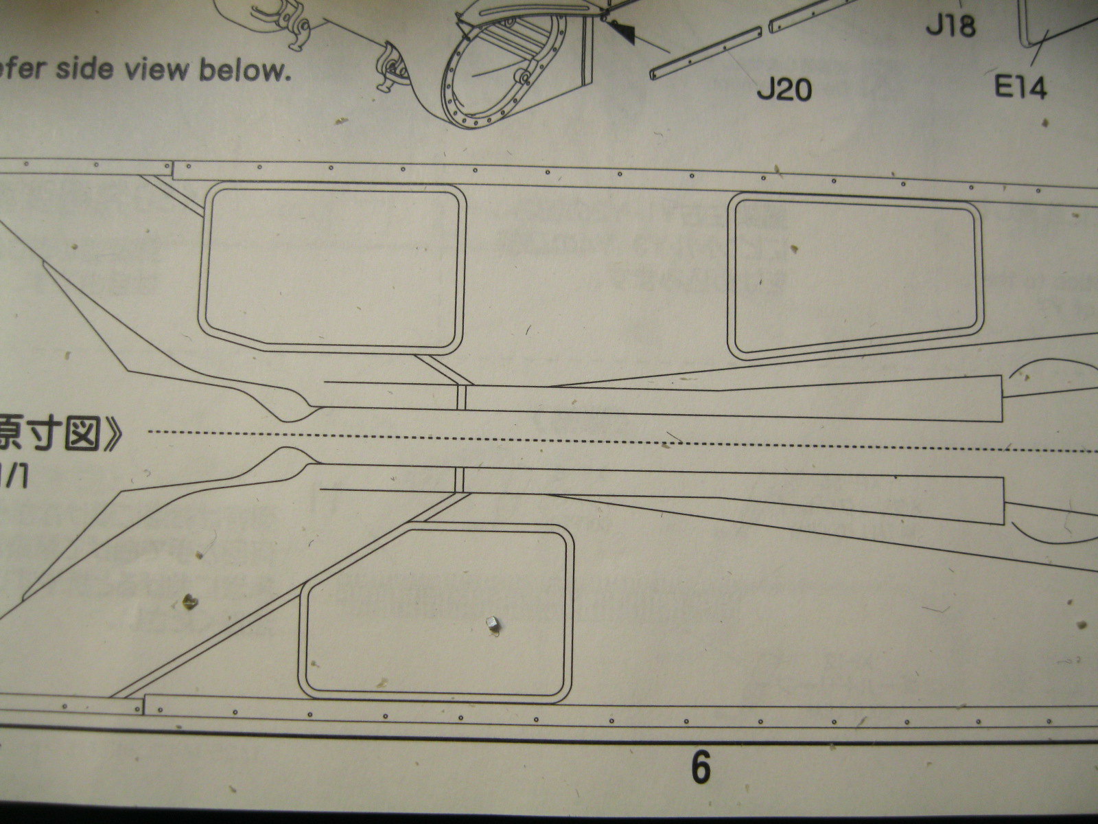
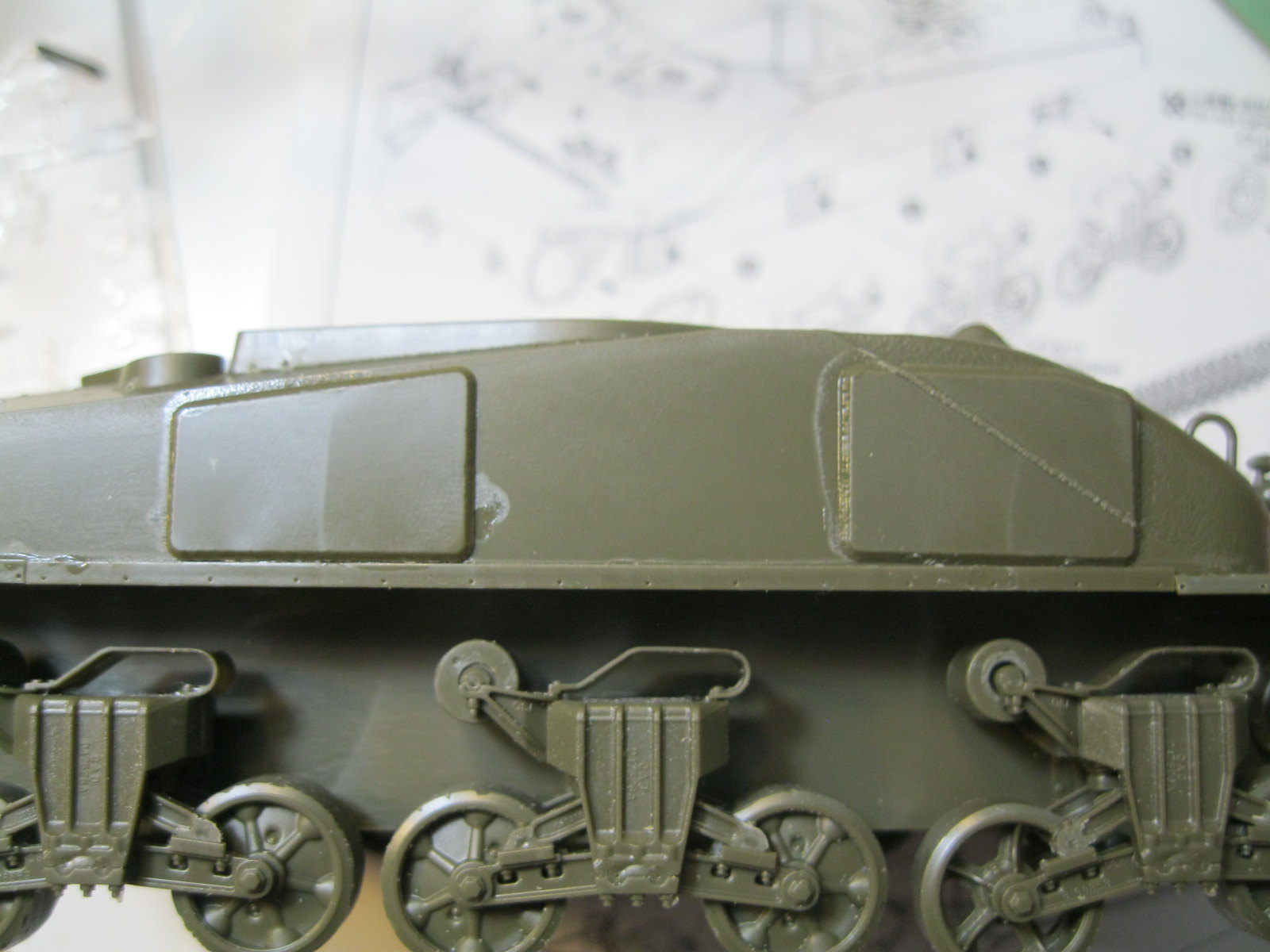
Next up is installation of the suspension and tracks. I am leaving the tracks off for now, and the idlers. I placed the drive sprockets simply because they are easy to remove. Next are the side skirt mounting strips and applique armor panels on the hull sides, again with a 1:1 scale guide to show where to put them.
IMG_9702 by russell amott, on Flickr
IMG_9703 by russell amott, on Flickr
IMG_9704 by russell amott, on Flickr
IMG_9705 by russell amott, on Flickr
IMG_9706 by russell amott, on Flickr
IMG_9707 by russell amott, on Flickr

On Chrysler built M4 composite tanks there should be a notch on the side skirts towards the rear. I just need a good reference to see where to make it and how big.

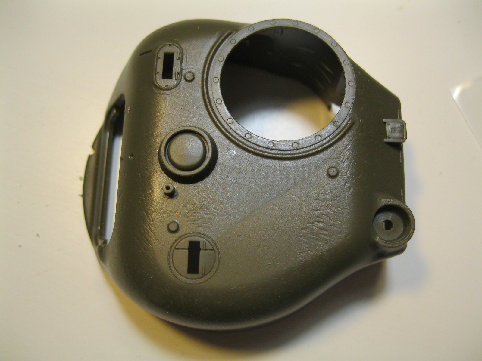
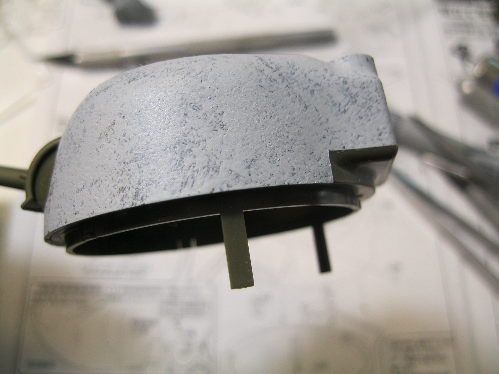
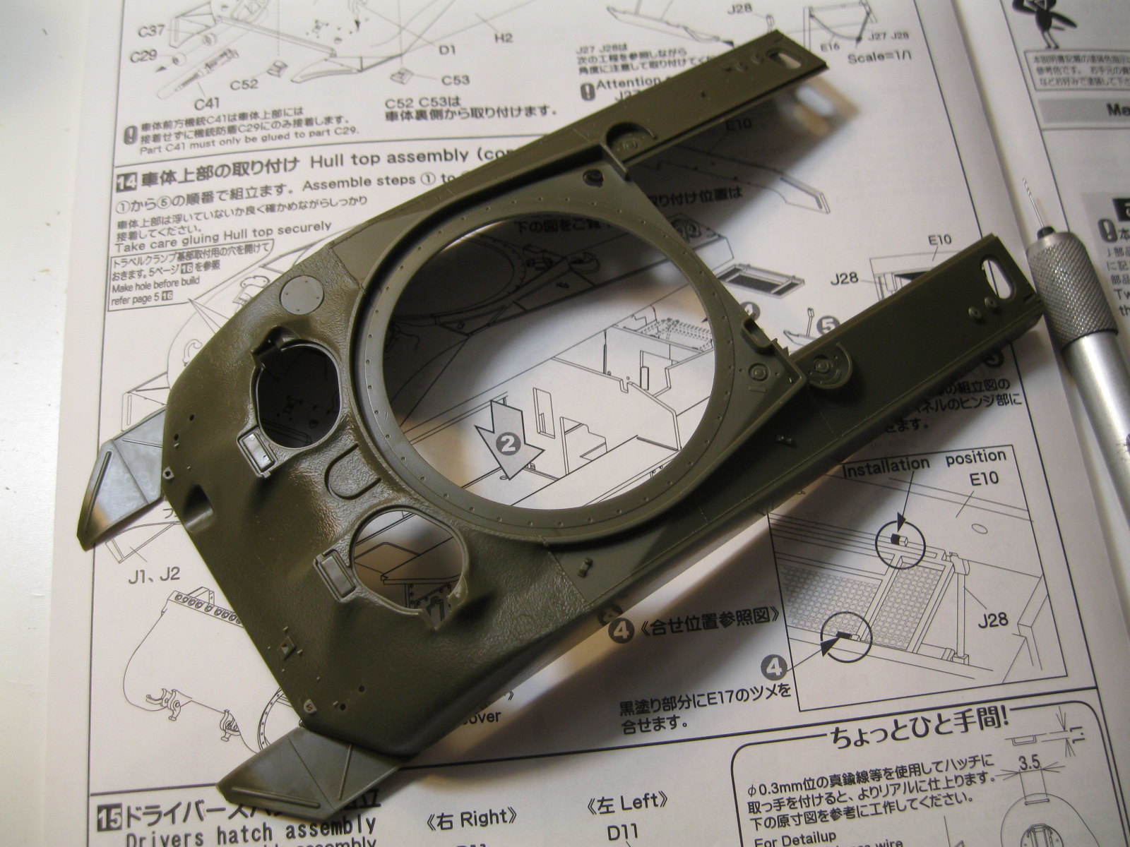
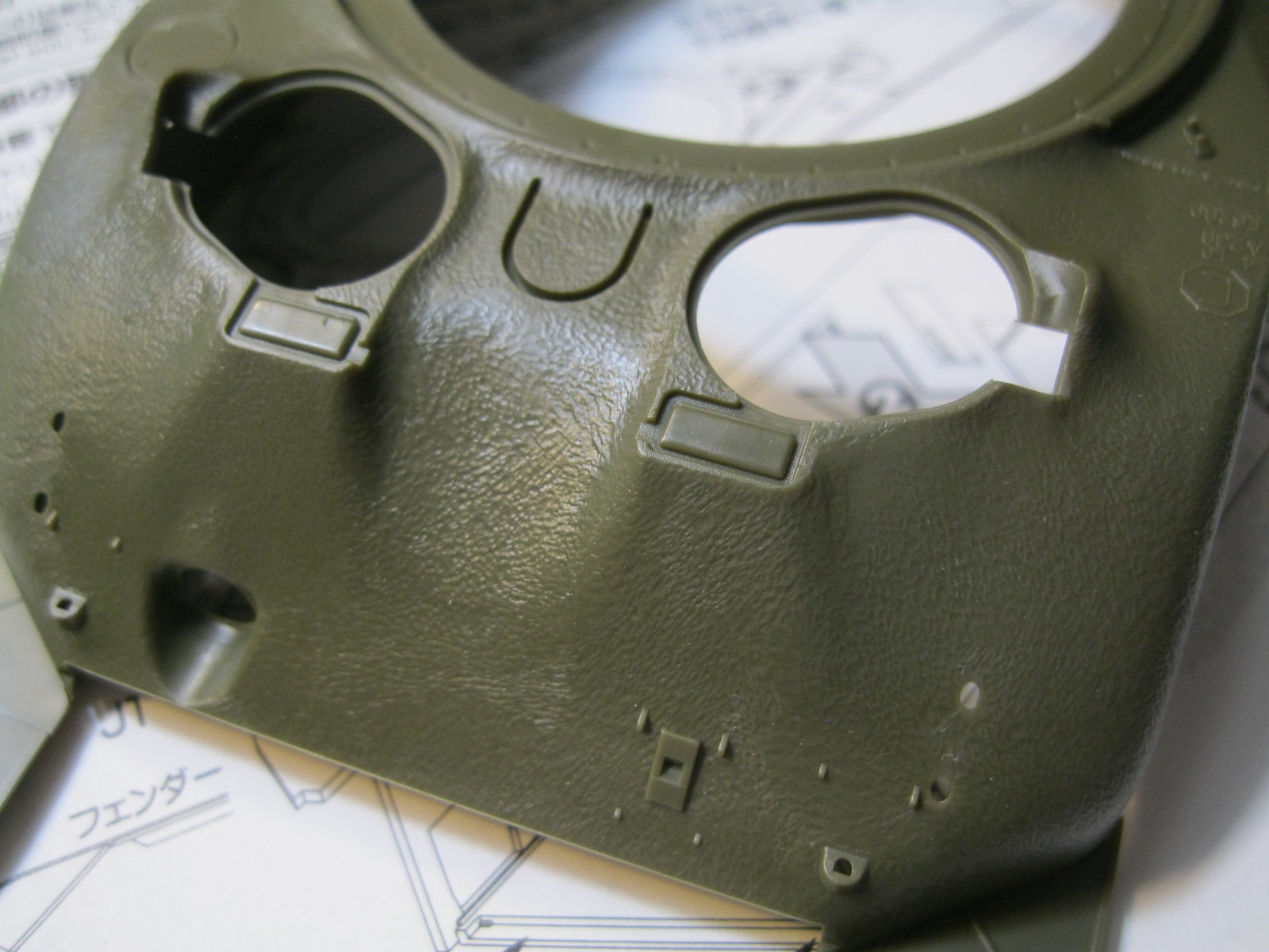
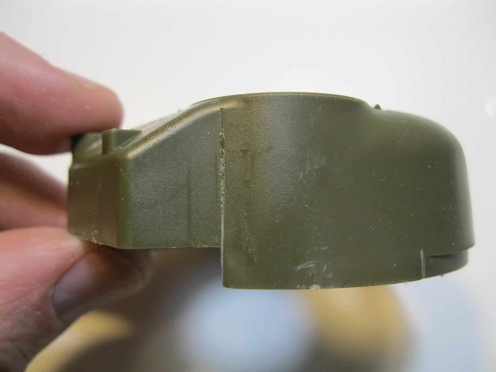
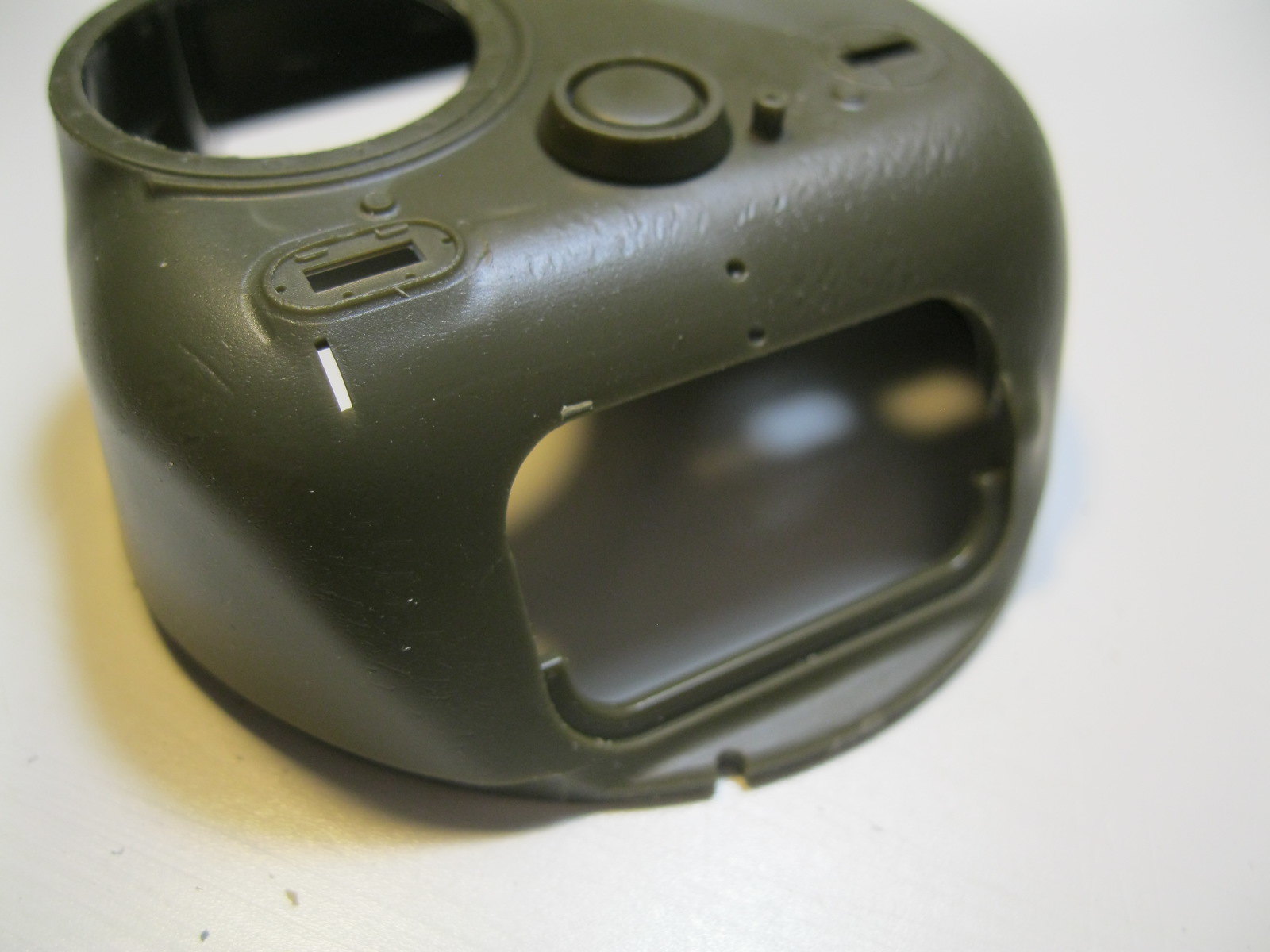
The turret has some casting texture in a couple of places, but the rest is smooth. There is a mold line on the right rear where the curve meets the bustle. I added some Mr. Surfacer to provide the texture. There are two small holes to open up for the sight, and a slot to fill in where the older style sight would fit. The smoke mortar opening is shown from the inside so you know where to make the hole. It says drill at a 45 degree angle but the plastic is so thin it doesn't really make a difference. I used some plastic tube previously and will do the same here.
IMG_9686 by russell amott, on Flickr
IMG_9687 by russell amott, on Flickr
IMG_9688 by russell amott, on Flickr
IMG_9689 by russell amott, on Flickr
IMG_9708 by russell amott, on Flickr
IMG_9709 by russell amott, on Flickr

I'll add the turret details and finish the small parts on the hull and then it should be ready for primer. I have the rubber block tracks from the M4 "Fay" kit that I will put on this kit.
bat-213
Visit this Community
Canada
Joined: December 30, 2011
KitMaker: 902 posts
Armorama: 788 posts
Posted: Friday, September 07, 2018 - 10:50 AM UTC
great job on the cliper very cool .
tangodown
#494
Visit this Community
New Brunswick, Canada
Joined: August 08, 2018
KitMaker: 213 posts
Armorama: 198 posts
Posted: Friday, September 07, 2018 - 11:28 AM UTC
Great work so far Russ. Nice clean job.
russamotto
Visit this Community
Utah, United States
Joined: December 14, 2007
KitMaker: 3,389 posts
Armorama: 2,054 posts
Posted: Friday, September 07, 2018 - 12:23 PM UTC
Roy and Cam, thank you.

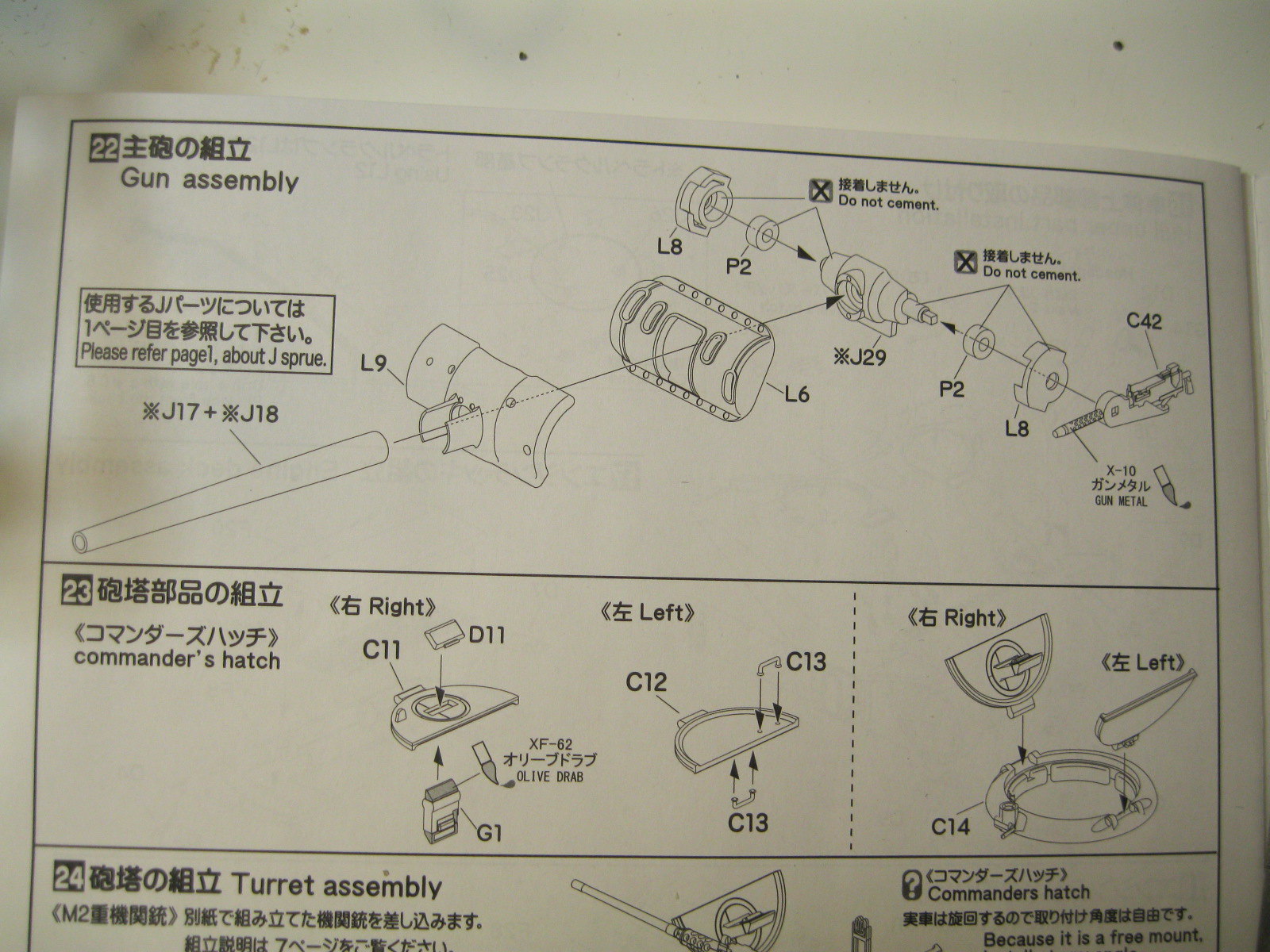
I have a small update. The next step in order is assembly of the .50 cal and mount, which I skipped for now as that will be added after the kit is finished. I moved ahead to the main gun assembly. The parts fit well and allow for nice movement, but there is no breech, though there is a well detailed coaxial .30 cal to go with it. The barrel comes in two parts. I have read on some forums that Asuka is prepping new kits and details, which will hopefully include a one piece barrel. Assembly of the parts is simple, though the barrel must go through the mantlet from behind, and not through the front as the instructions indicate. With that in place I added some turret details. There are ejector pin marks on the inside faces of all hatches so I went over them with some Tamiya extra thin to hide them as the location is a little difficult to get to with the tools I have on hand, and it gave them somewhat of a cast texture.
IMG_9710 by russell amott, on Flickr
IMG_9711 by russell amott, on Flickr
IMG_9712 by russell amott, on Flickr
IMG_9713 by russell amott, on Flickr
IMG_9714 by russell amott, on Flickr
IMG_9715 by russell amott, on Flickr
I improvised with the smoke mortar by using a piece of sprue set through the hole. I will drill out the end and trim it down to length. The brush guards were added as well. I will go through the instructions to make sure I have added everything before the primer coat. I am going through the figures I have to see what will work and maybe give it a little life.
IMG_9716 by russell amott, on Flickr
IMG_9717 by russell amott, on Flickr
IMG_9718 by russell amott, on Flickr
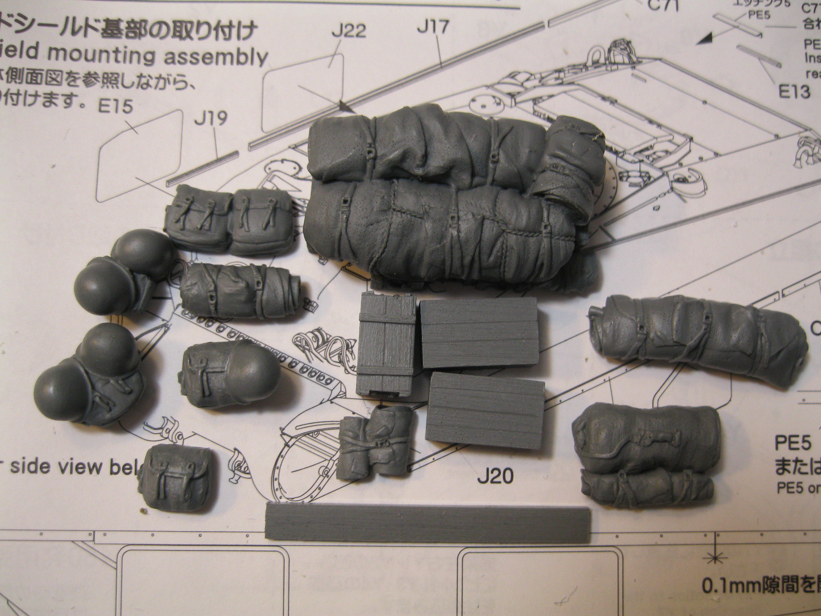
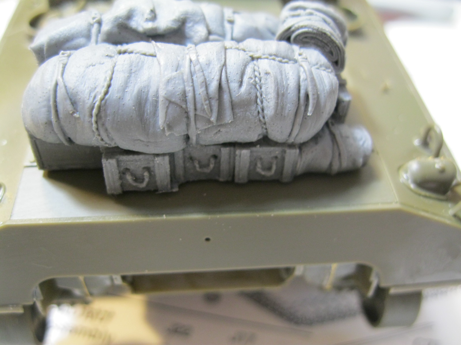
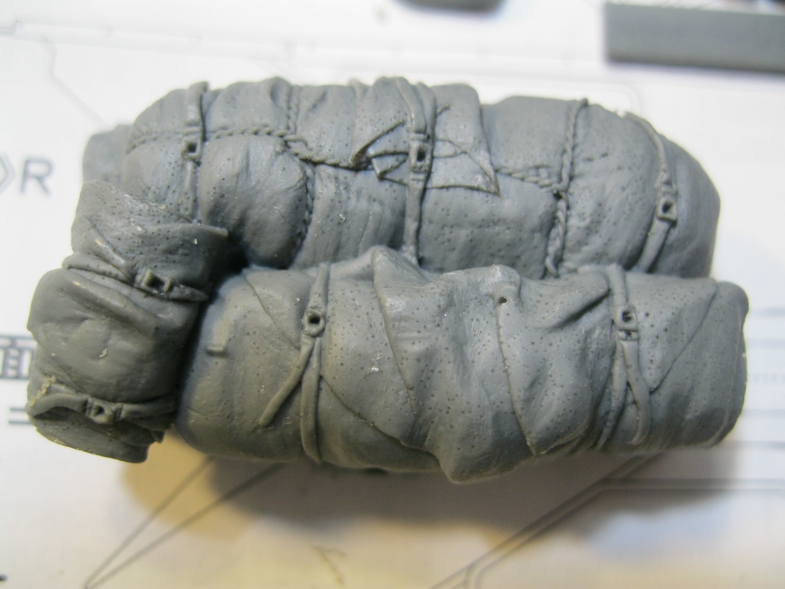
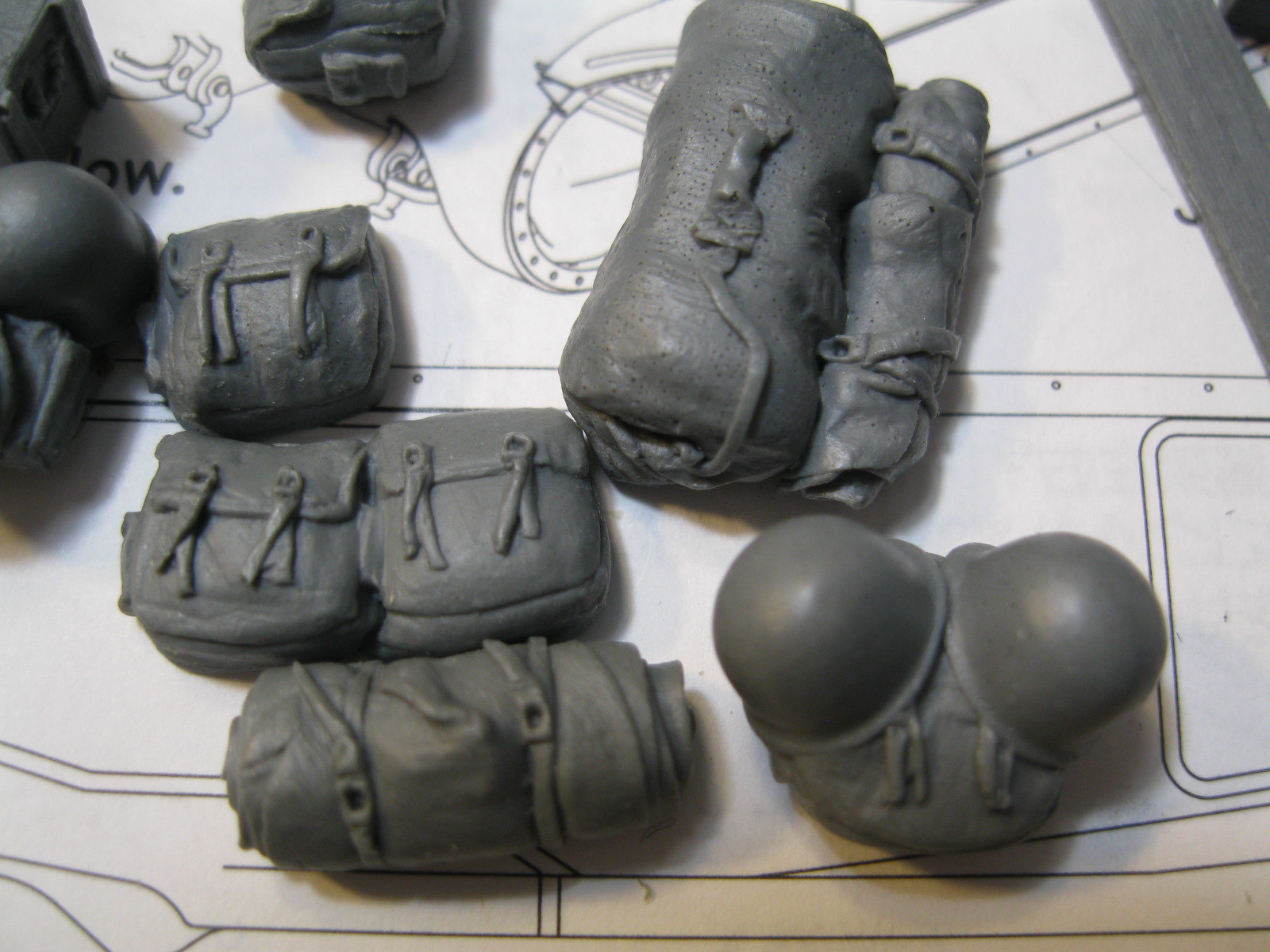
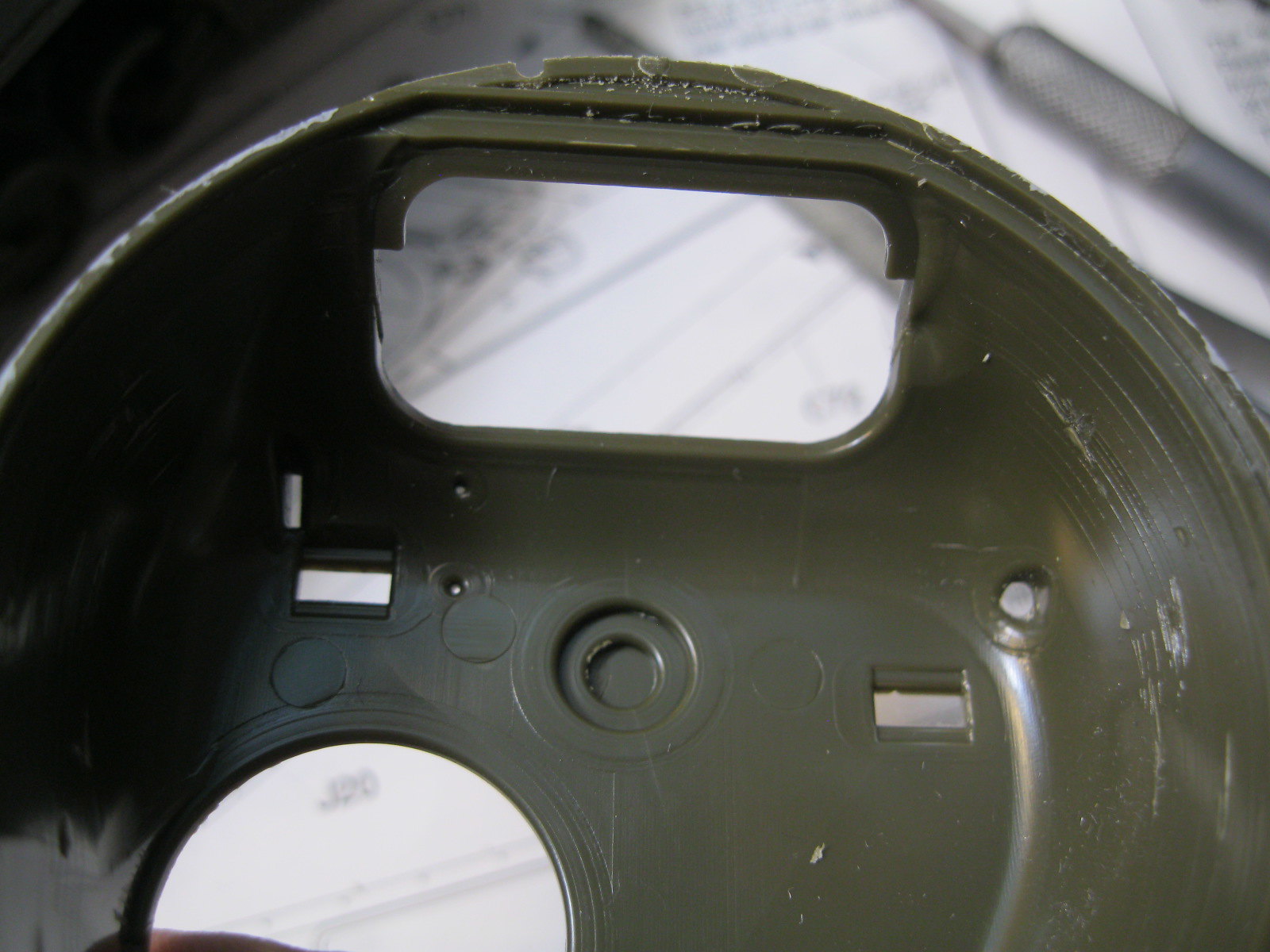
The kit includes some Value Gear resin pieces as a nice touch. The largest piece is for the engine deck and consists of large rolls set on ammo and ration crates. There are some haversacks, poncho rolls, helmets with gear and three crates-two ration and one generic. The included board fits between the fenders.
IMG_9719 by russell amott, on Flickr
IMG_9720 by russell amott, on Flickr
IMG_9721 by russell amott, on Flickr
IMG_9722 by russell amott, on Flickr
IMG_9723 by russell amott, on Flickr

There are little pinhole bubbles on the resin. I am hoping a coat of primer covers them. I won't put the hatches on until I know what I am going to do for figures. Thank you for looking and let me know if I missed something.
bat-213
Visit this Community
Canada
Joined: December 30, 2011
KitMaker: 902 posts
Armorama: 788 posts
Posted: Saturday, September 08, 2018 - 03:29 PM UTC
dam nice work ,
m4sherman
Visit this Community
Arizona, United States
Joined: January 18, 2006
KitMaker: 1,866 posts
Armorama: 1,808 posts
Posted: Saturday, September 08, 2018 - 04:43 PM UTC
It's looking good. The lower hull can be tricky, but after a couple is less of a challenge.

For a second I thought your friend was a rabbit! Lousy glasses!
russamotto
Visit this Community
Utah, United States
Joined: December 14, 2007
KitMaker: 3,389 posts
Armorama: 2,054 posts
Posted: Saturday, October 13, 2018 - 12:43 PM UTC
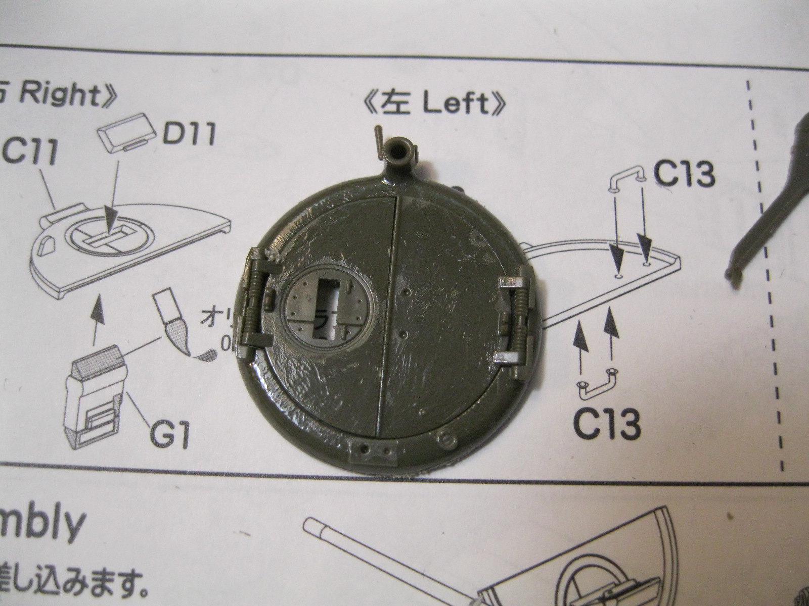
It has been a while since the last post but I have made some progress. First was to add some detail to the hatches. Wire was used for the handles and I placed the latch for the commanders split hatch. I had to improvise with the pad on the inside. A part number tab worked well. The details for this are included but aren’t called out in the instructions. I also added a bracket for the spare road wheel on the hull front. I had some extra etch frame that I cut and bent to shape. I did anbase coat with Takmiya olive drab lightenend with dark yellow. After it dried I went over the kit with an oil dot treatment and added decals. The hull side stars should be larger when compared with the photo and I placed the unit code on the glacis too high compared with the photo. Then I painted the road wheels. I have done an oil wash on the road wheels but don’t have a photo of that.

https://flic.kr/p/NfTrti
https://flic.kr/p/29fC9Ly
https://flic.kr/p/29fC93Q
https://flic.kr/p/29fC8uL
https://flic.kr/p/2c22bGH
https://flic.kr/p/29fC7zj
https://flic.kr/p/29fC6Yj

Next up is weathering. The tank is covered in mud and the bogies in particular are layered in mud. I don’t know that I can pull that look off. The photo was taken in October or November in Nancy during an overhaul. The side has been partially wiped down which makes me wonder if they were getting ready to paint the unit number on the side. Photos of tanks from 6th armored division from November through the end of the Bulge show large hull numbers and 68th tank battalion would have a white triangle, and they also had the extended end connectors installed. China Clipper would have seen considerable action from Brest up through the assault on Metz so I can keep it cleaner. I’m also trying to figure out the stowage on the turret rear. Looks like boxes attached with straps. I haven’t seen any other photos of China Clipper but I have been looking at other tanks from the 6th and the welded bar on the turret runs from about the mid point on the turret side around to the side of the rear bustle, and is bent to conform with the turret shape. I will study a bit more and work on the shape. Thanks for looking and if you have any insight or suggestions please let me know.
KurtLaughlin
Visit this Community
Pennsylvania, United States
Joined: January 18, 2003
KitMaker: 2,402 posts
Armorama: 2,377 posts
Posted: Sunday, October 14, 2018 - 02:33 AM UTC

Quoted Text


On Chrysler built M4 composite tanks there should be a notch on the side skirts towards the rear. I just need a good reference to see where to make it and how big.


Click on this photo and it will zoom in.

http://the.shadock.free.fr/sherman_minutia/manufacturer/m4composite/SC212887.jpg

It's between the #4 and #5 skirt attachment hole from the rear. Given that the strips overhang the hull sides, I'd say that the top of the notch is flush with the underside of the hull.

The rest will require some judgement on your part.

KL
 _GOTOTOP