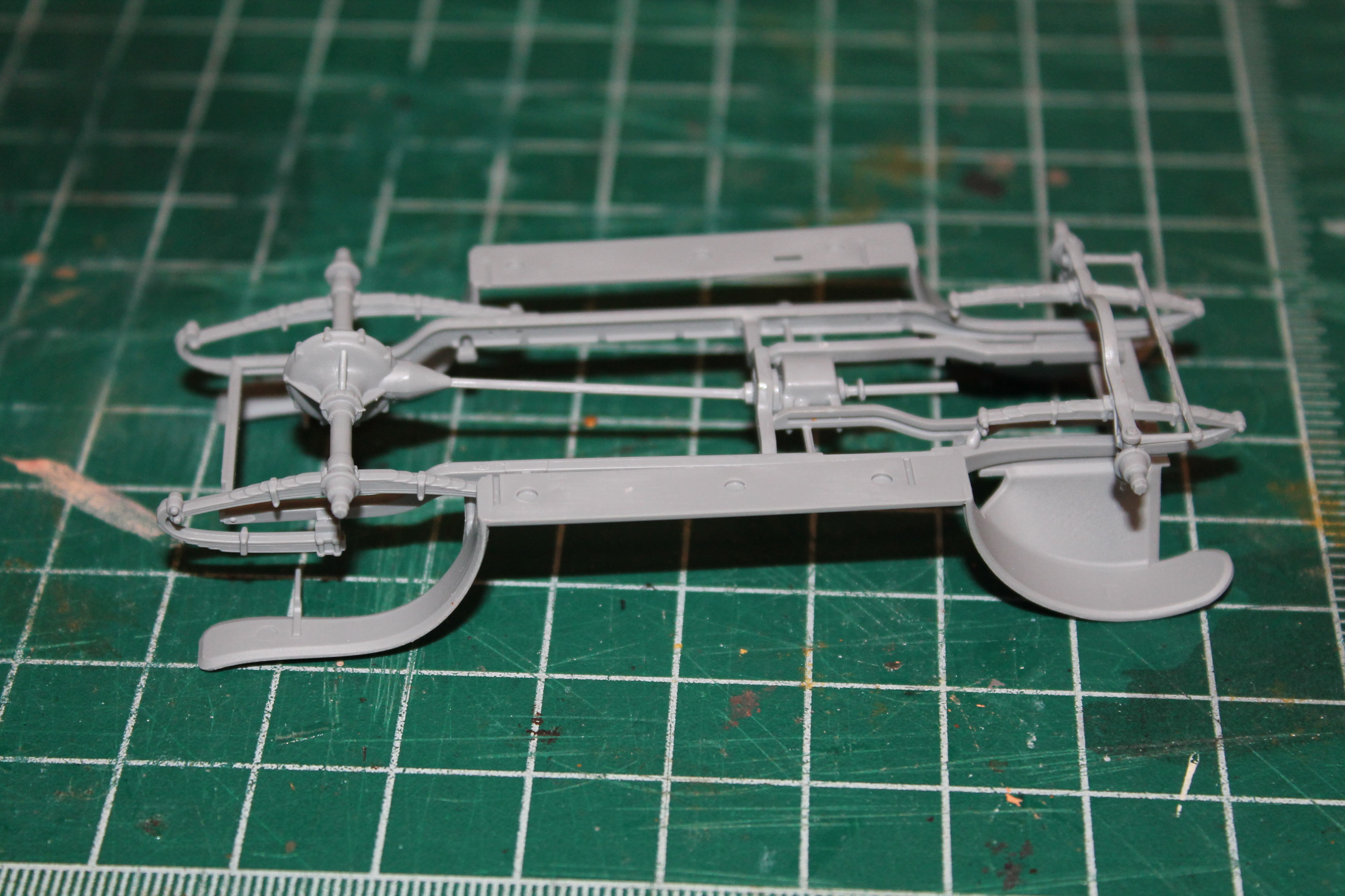
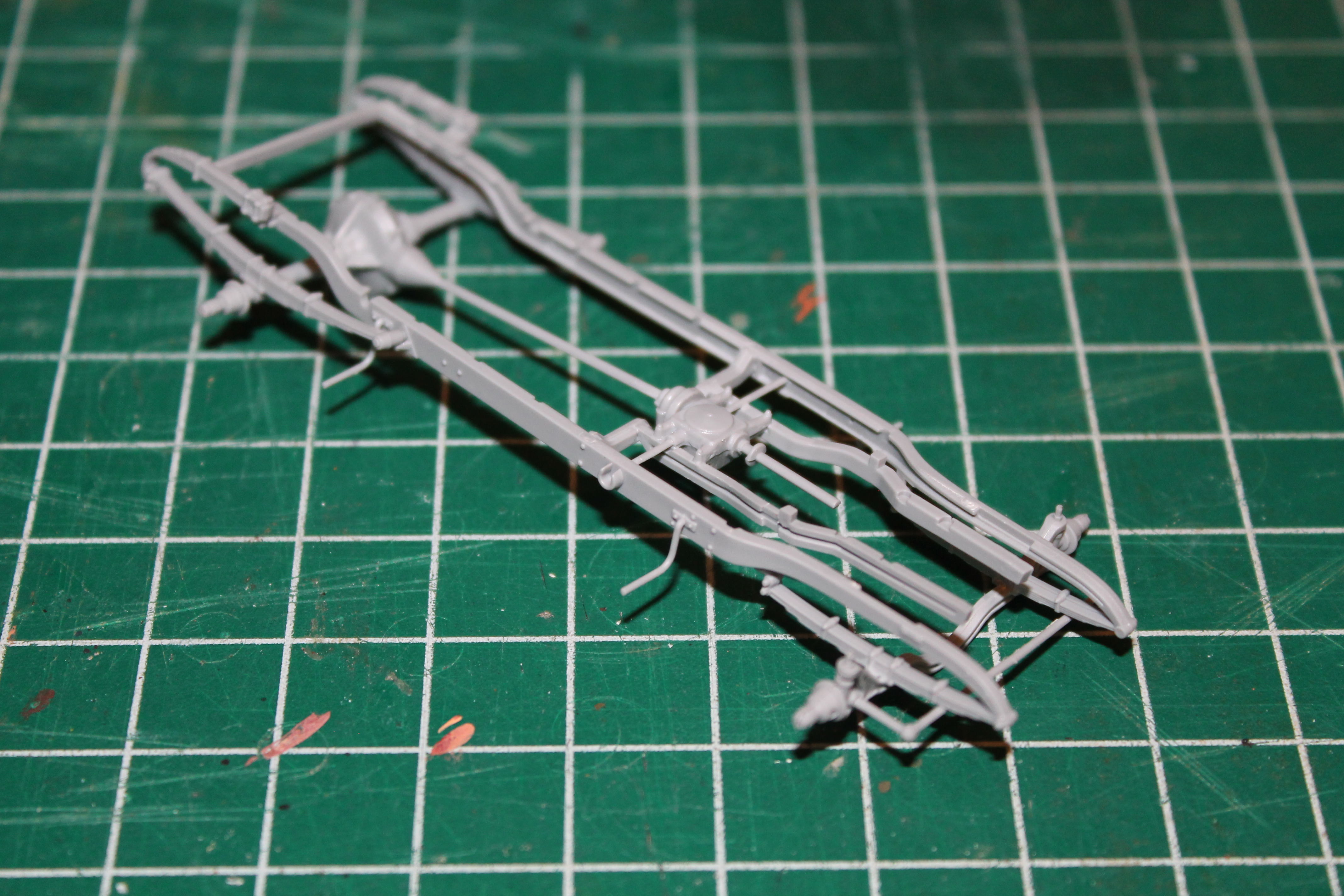
Sorry it has been so long since the last update. Have finally been able to get some more assembly work done. As usual, I have been skipping around the order of steps in the instruction sheet. I went to Step 9 and cemented part A33 into place. I did this to facilitate painting. I determined by test fitting that the chassis could be slid into place with A33 already attached.
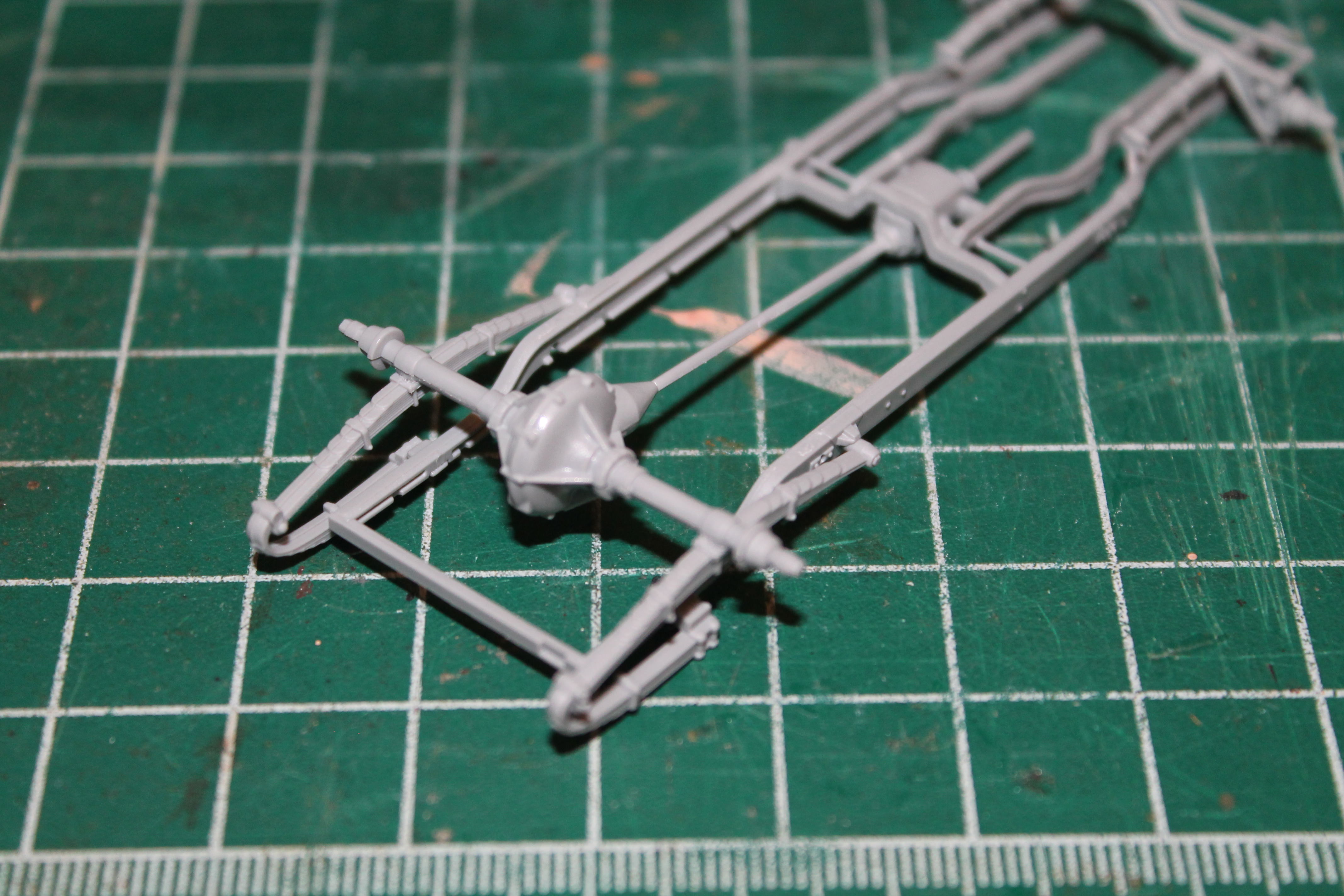
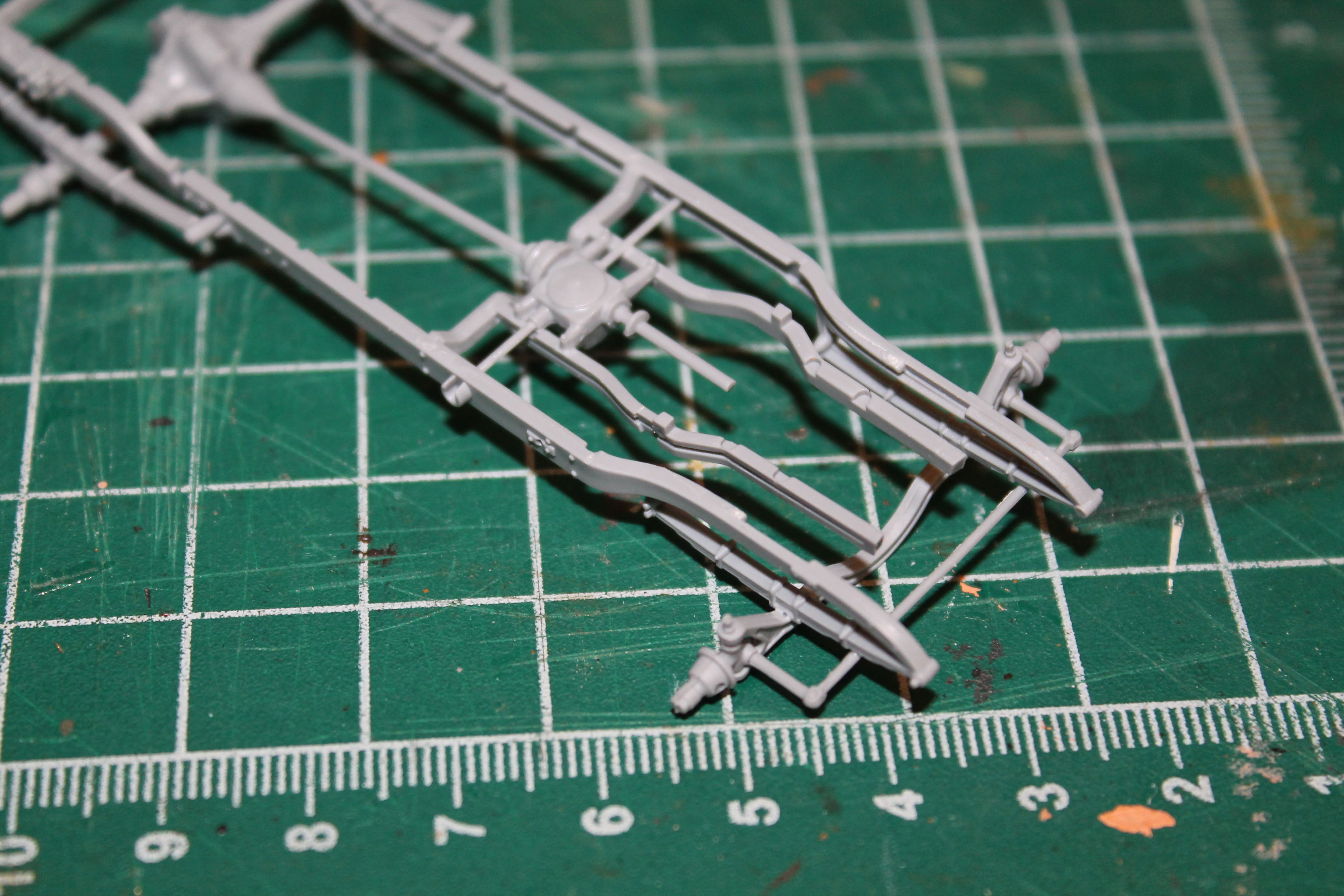
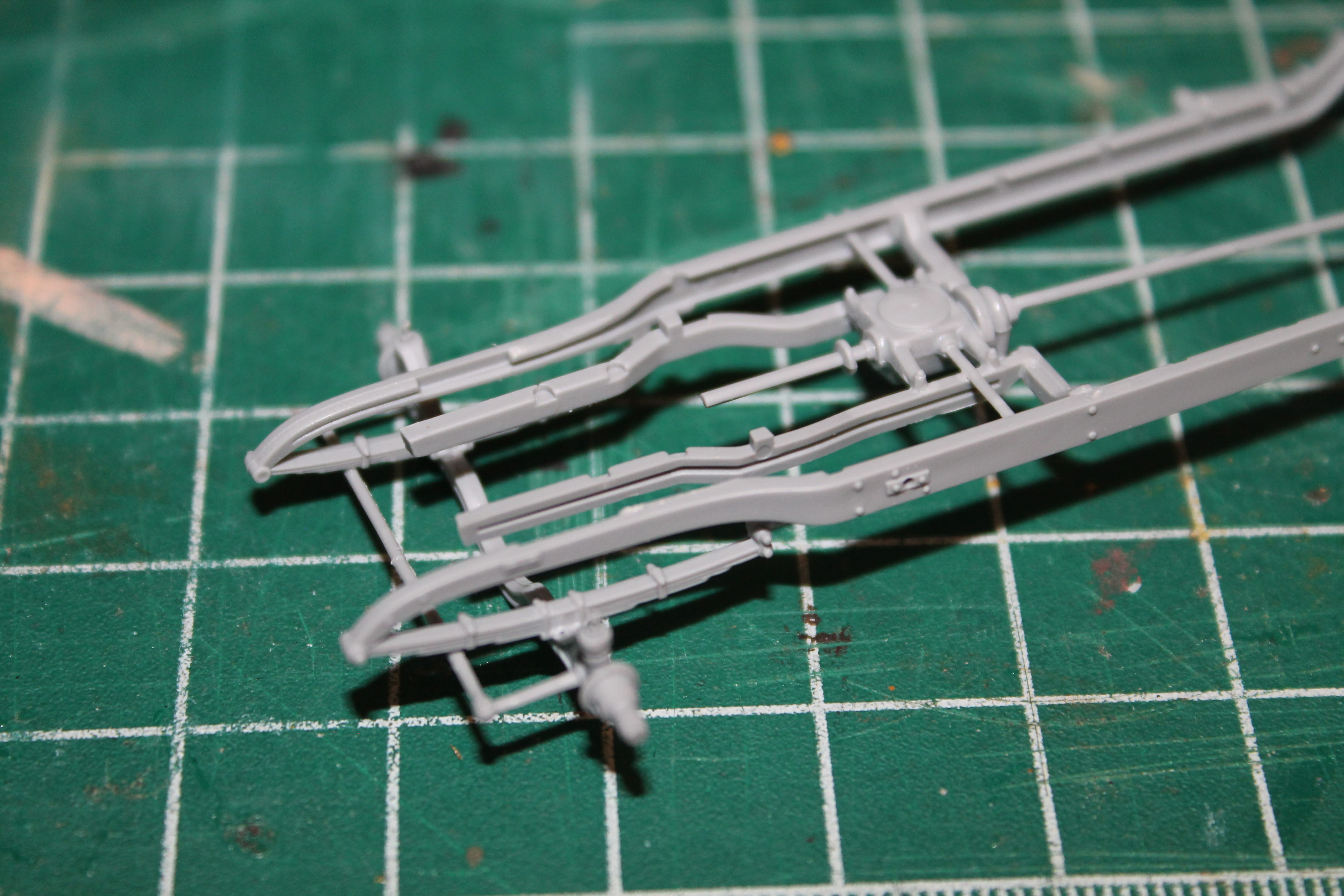
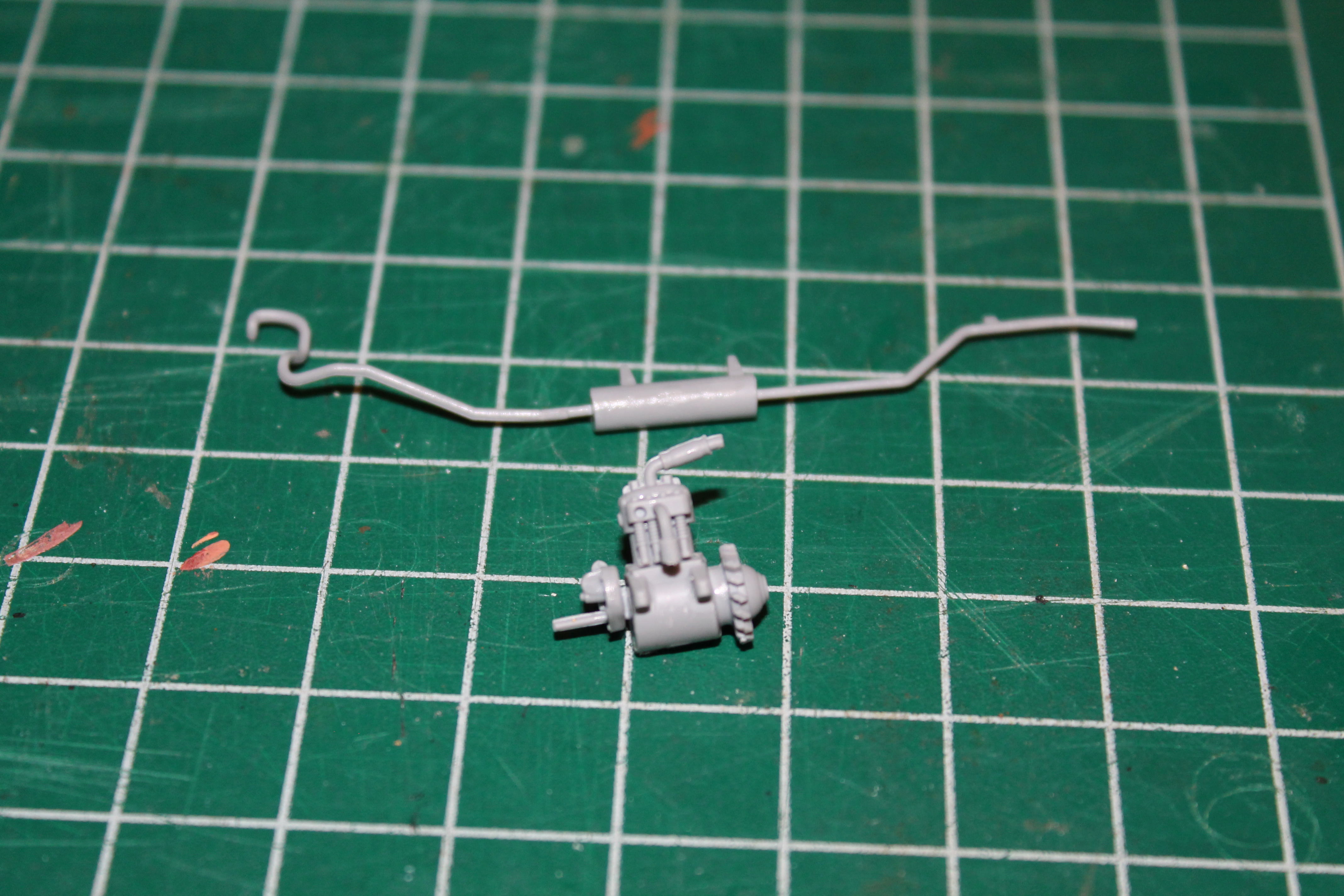
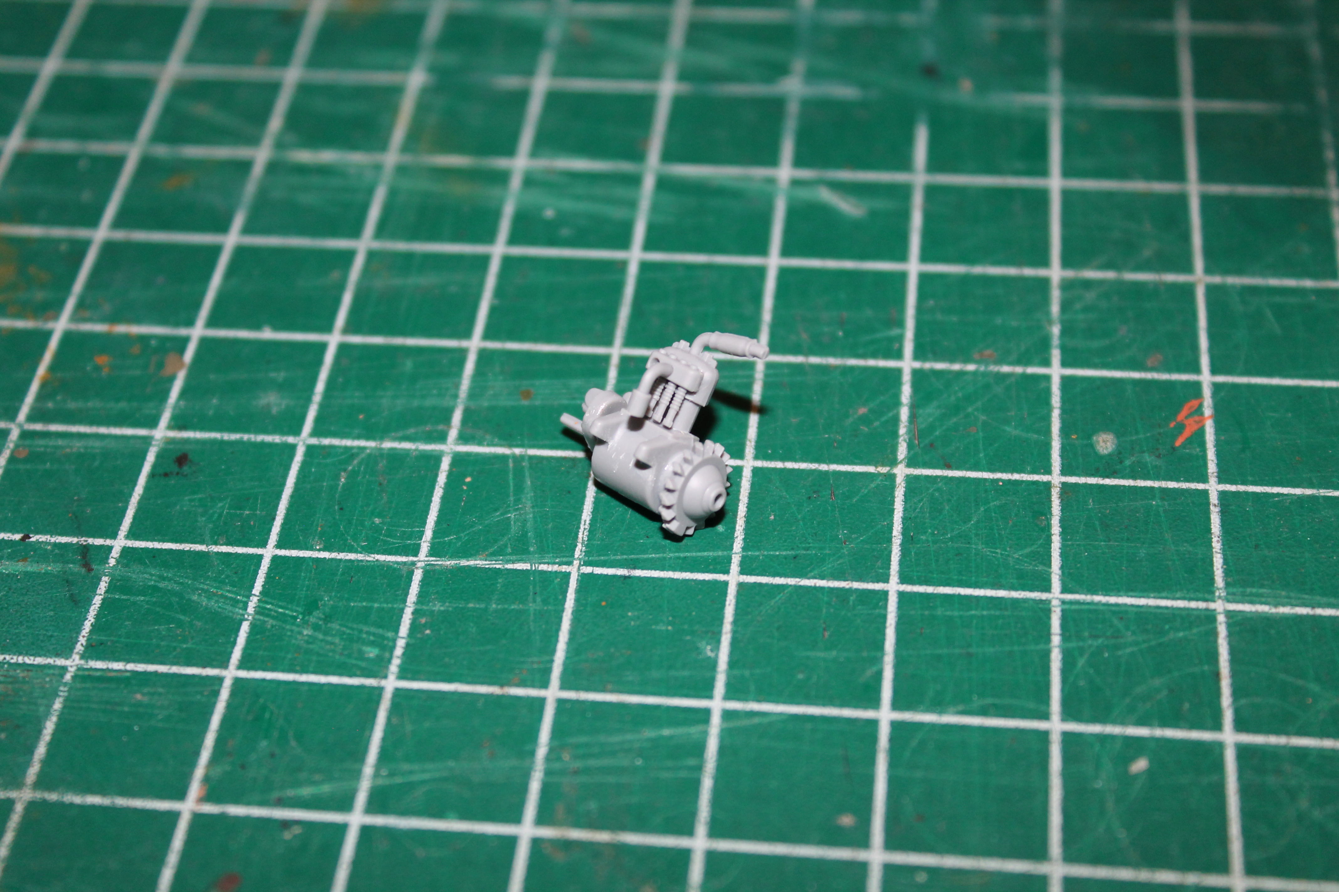
Apparently, Renault took the rough roads of the time into consideration when designing the AG1. The engine and transmission are completely protected underneath the frame. Part A36 is added in Step 41 to cover the transmission. As mentioned, the kit has a complete engine, but little will be visible from below. In the photo you can also see the injection pin marks that had to be filled.
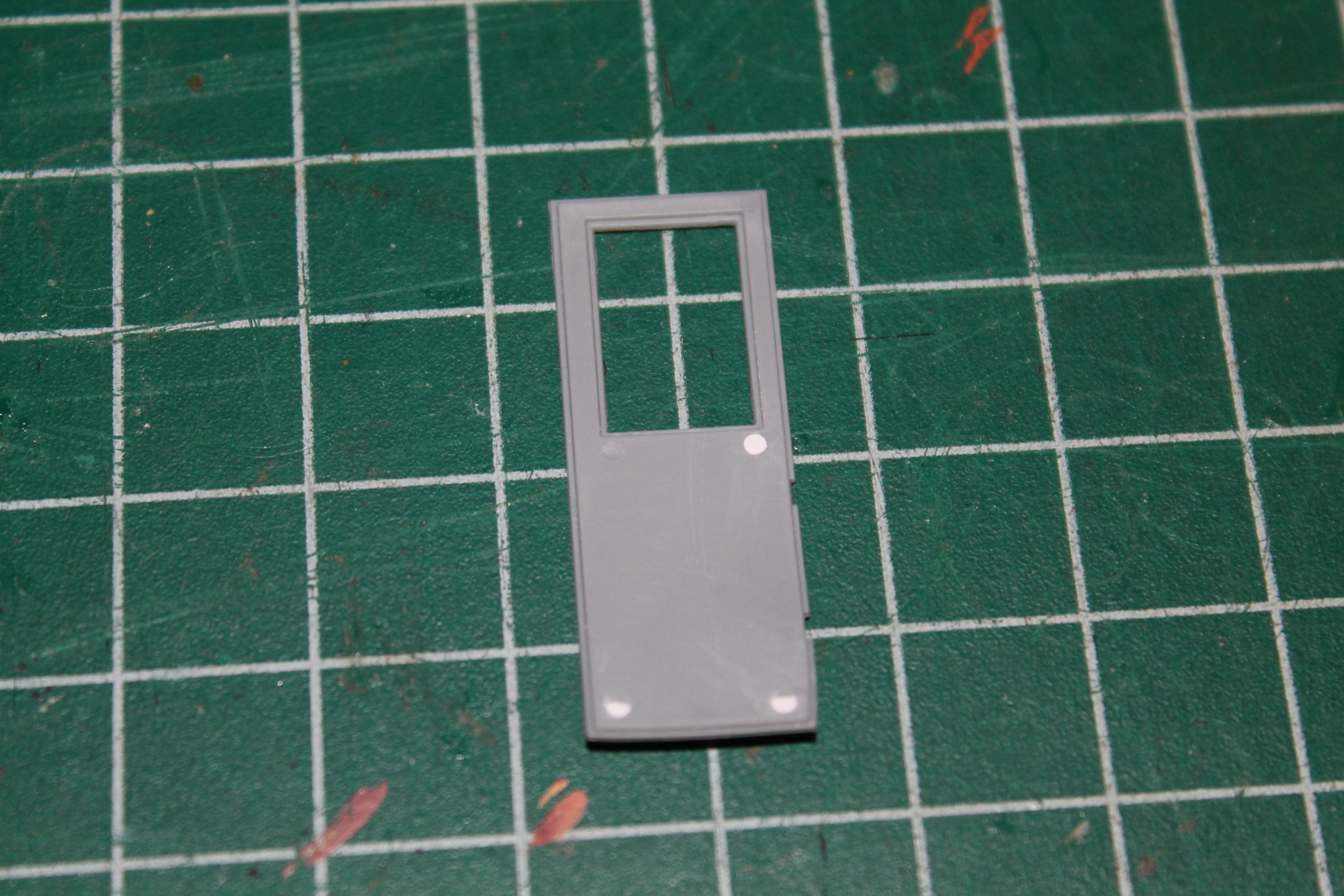
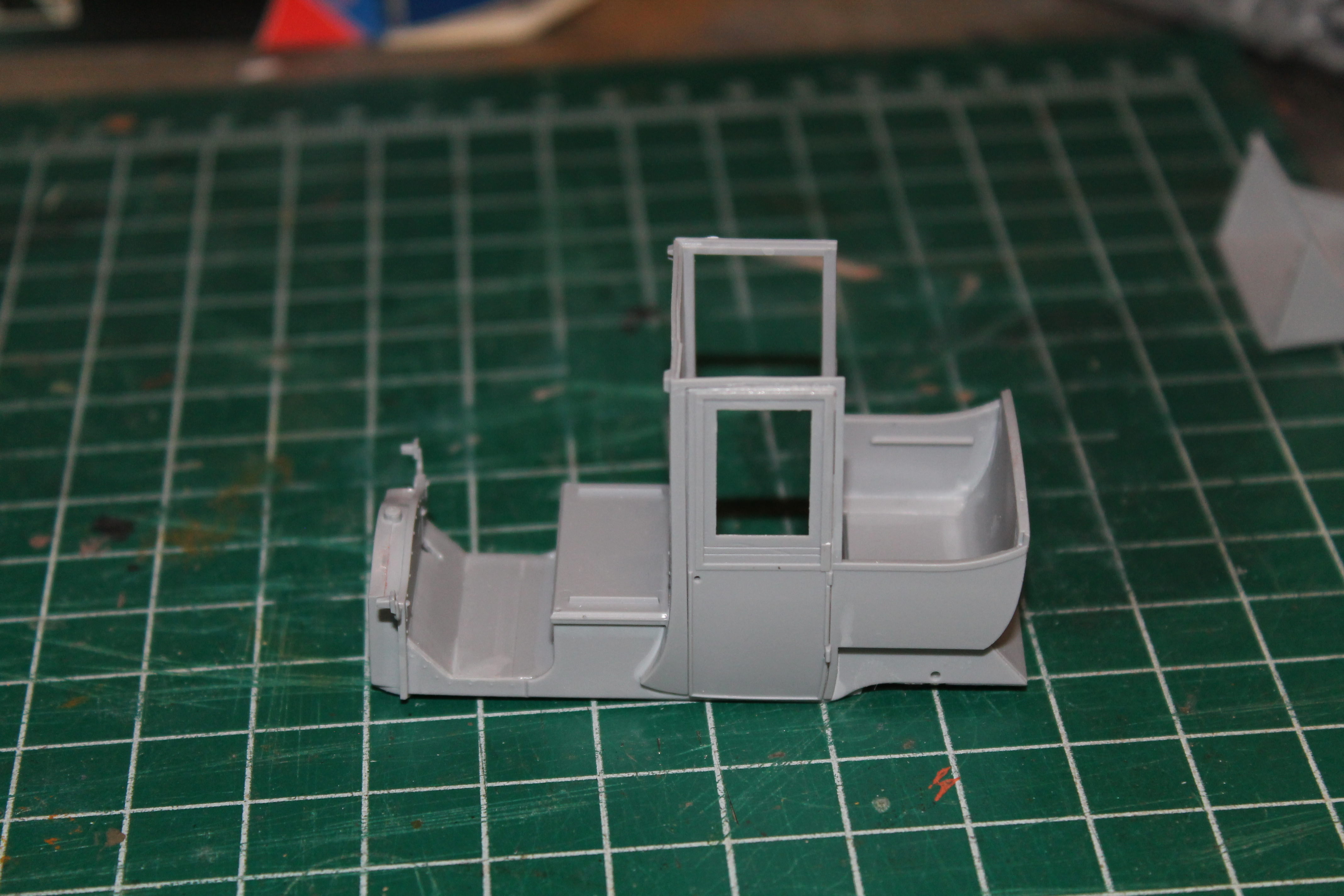
Next, I went on to add one door to the body assembly. Leaving one door free to be assembled in the open position. Again there were some shallow pin marks to be dealt with on both doors.
In the instruction sheet, the roof is assembled by first cementing the two sides (parts B9 & B10) to the rear body, and then adding the back and top sections (B8 & B11). I assembled the whole roof as one unit.
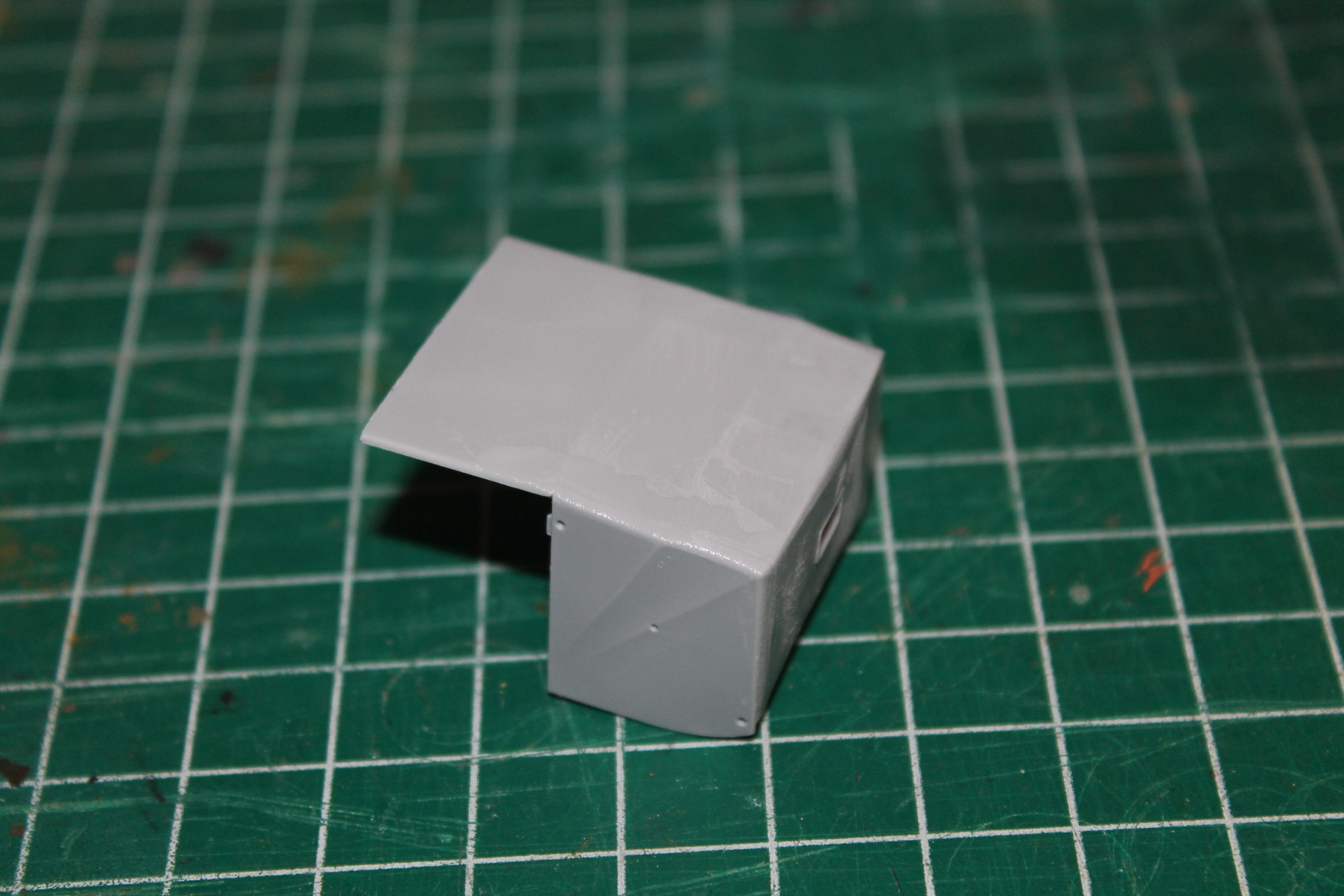
The roof temporarily fixed into place.
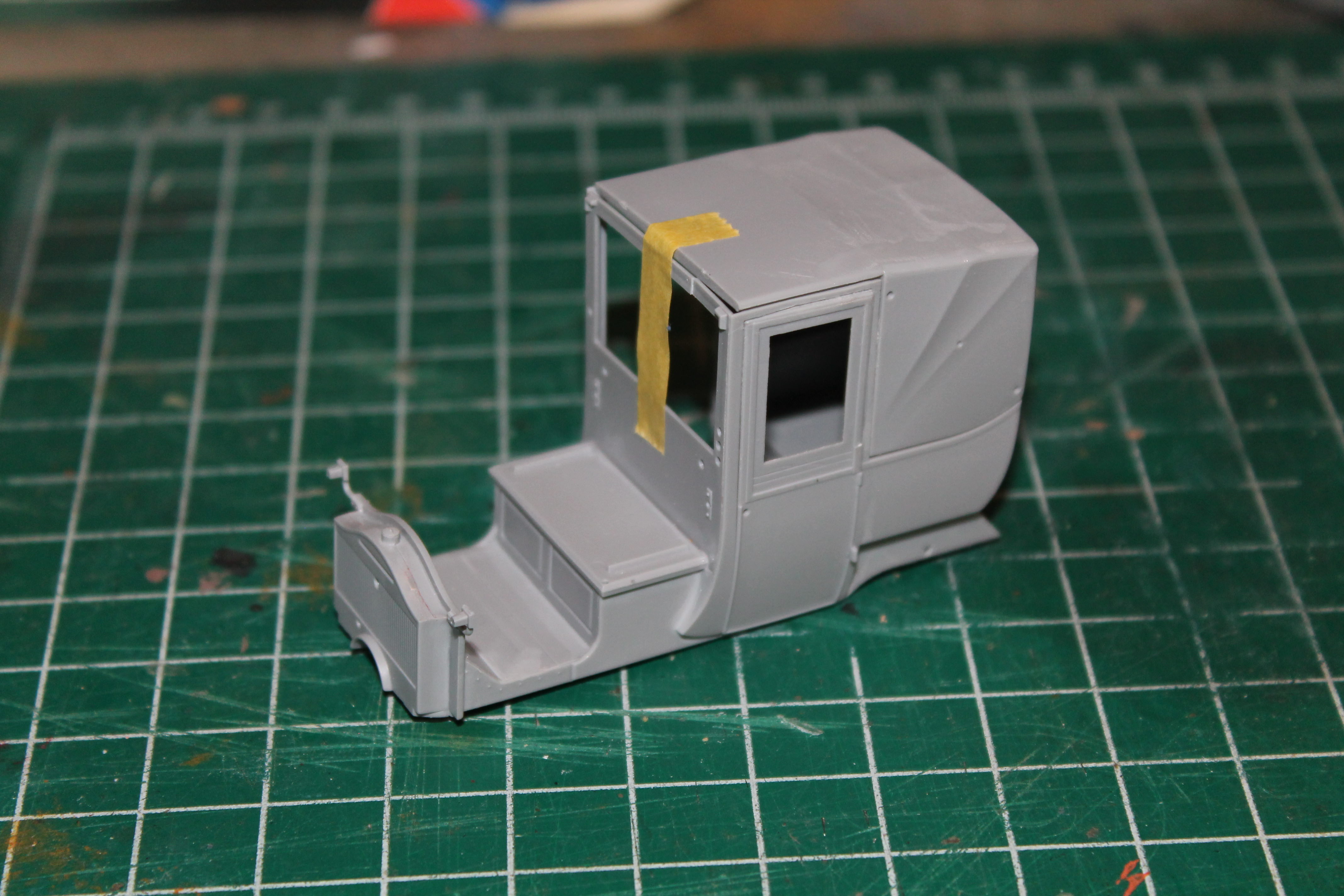
As you can see the fit is excellent, as it has been with all parts so far. It might have been nice if ICM had included the option for building the model with a folded roof as well. Although, I don't know how often, if ever, Paris taxis went about with the top down.
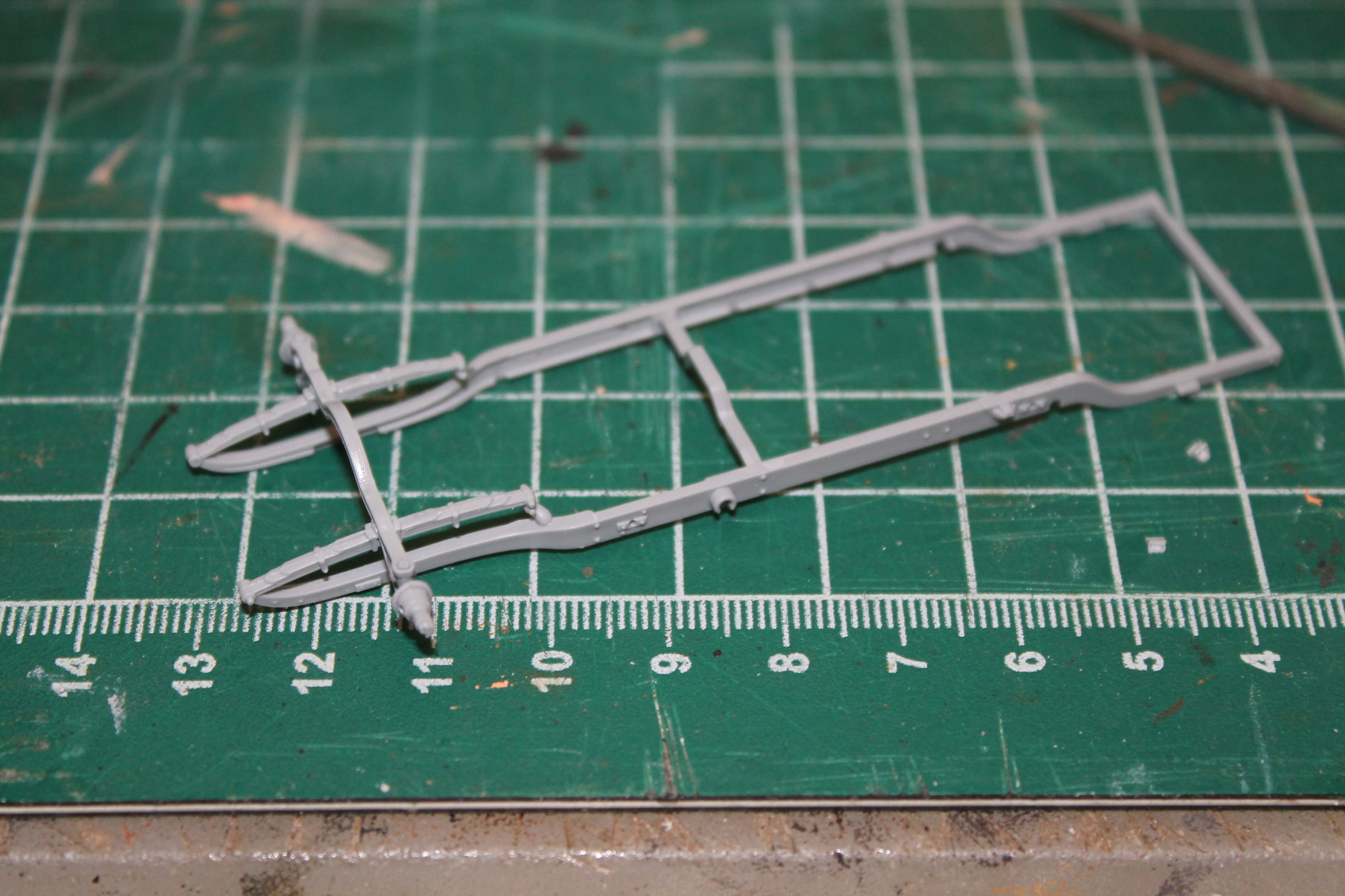
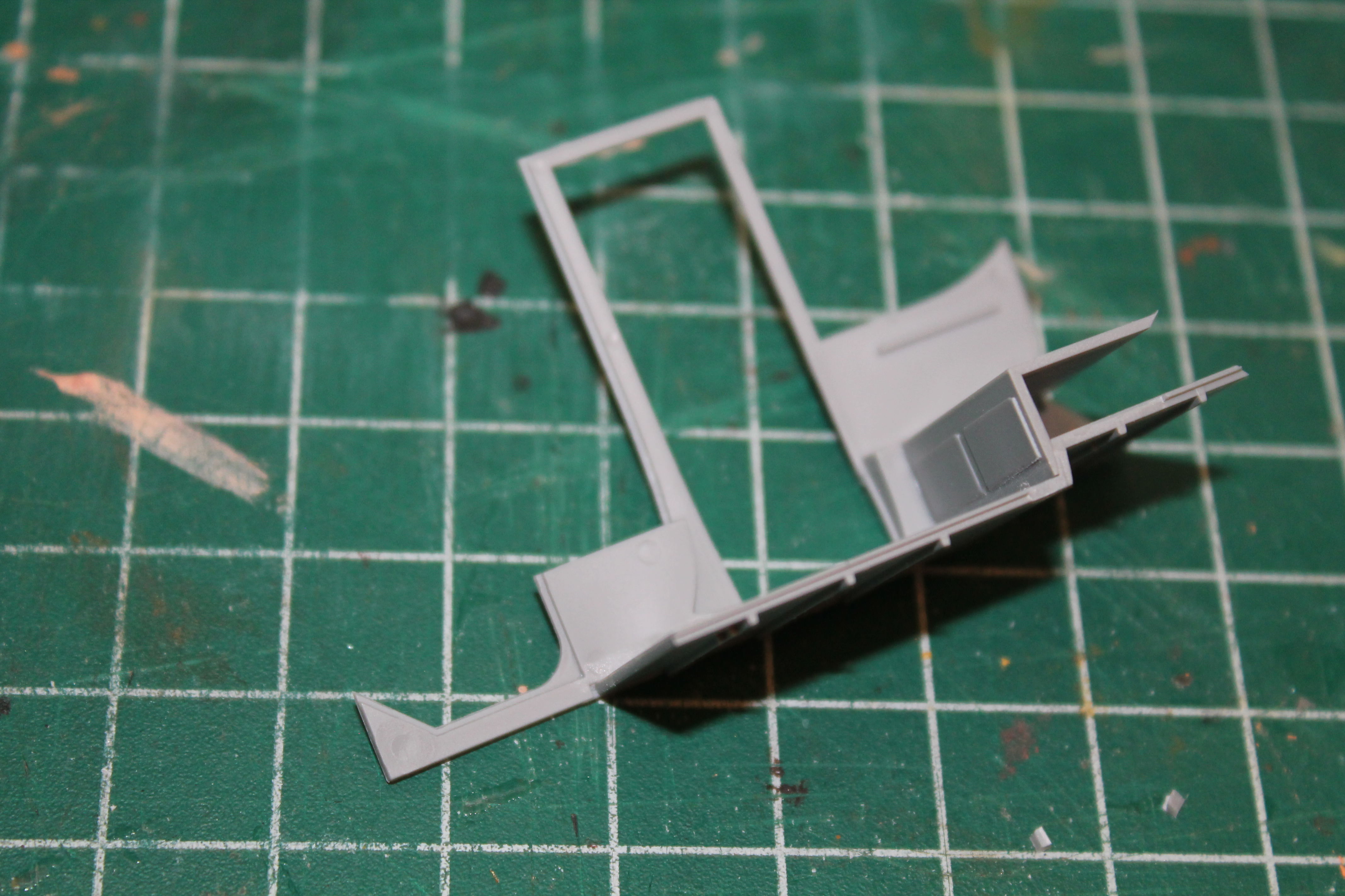
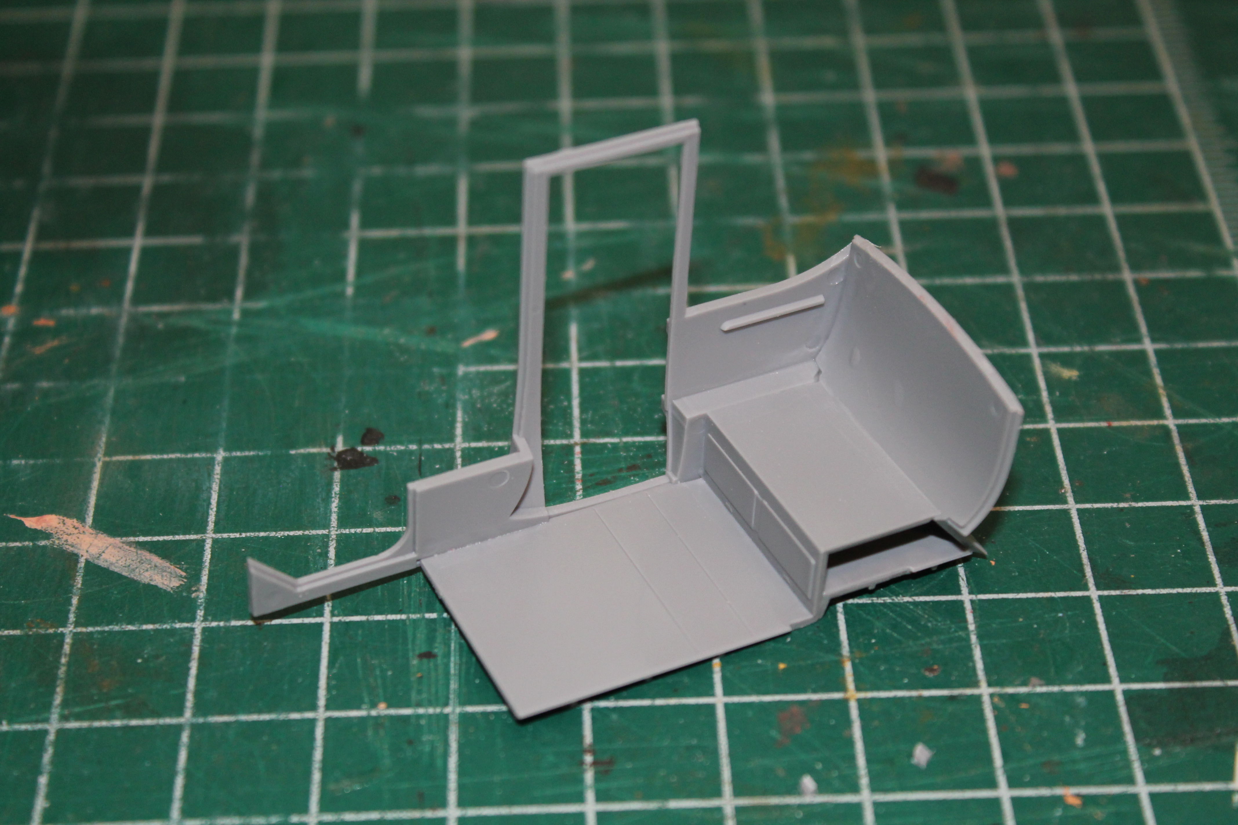
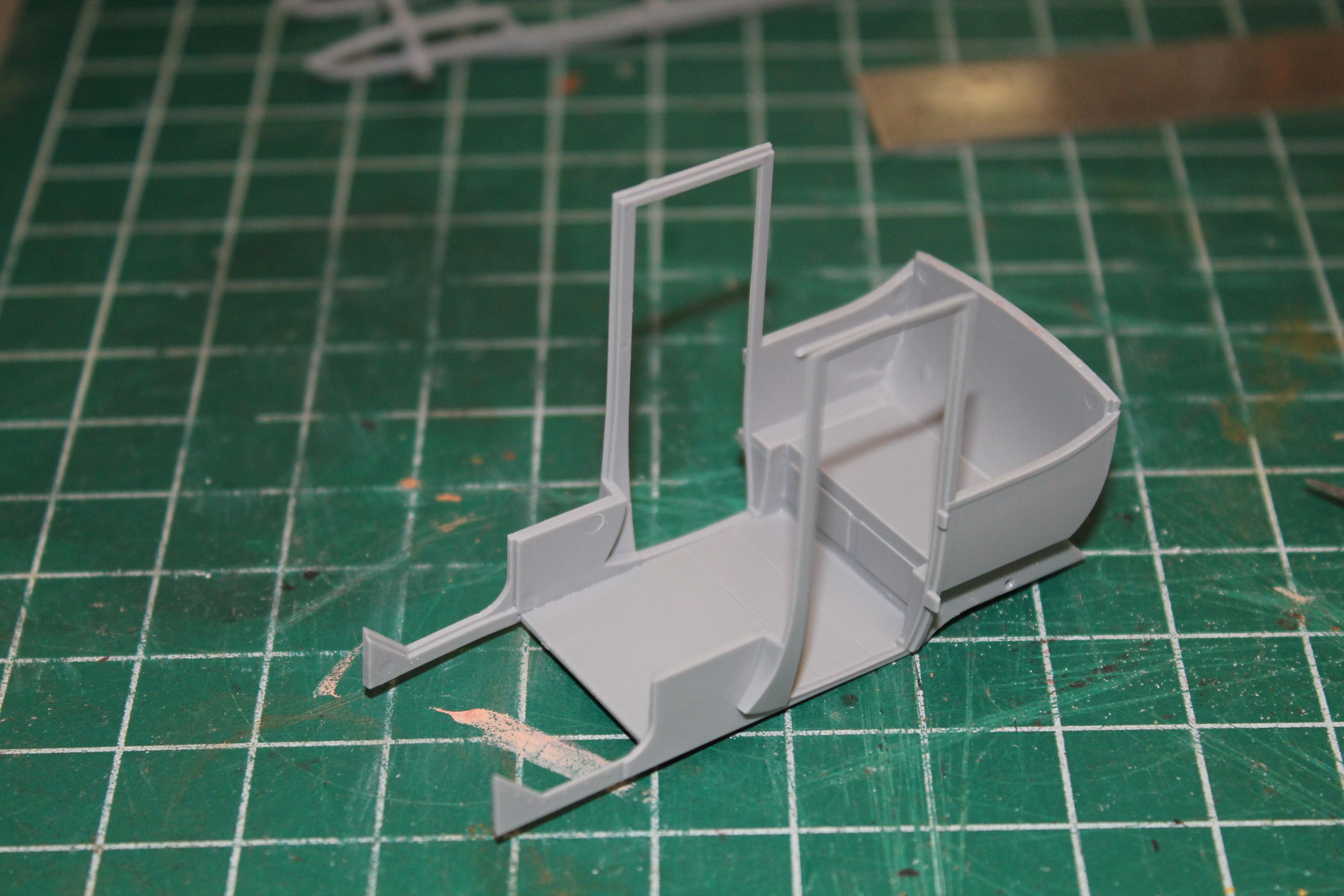
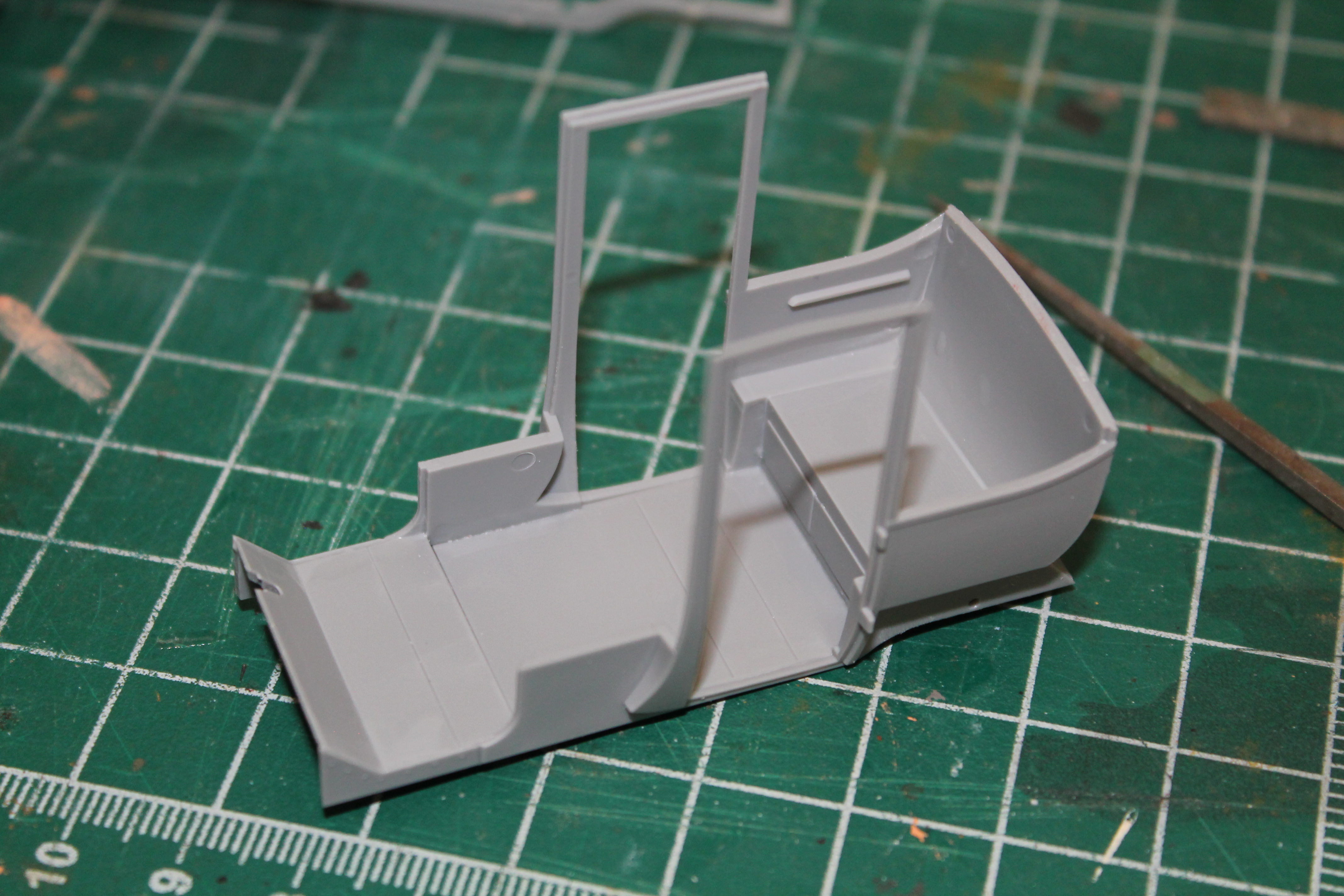
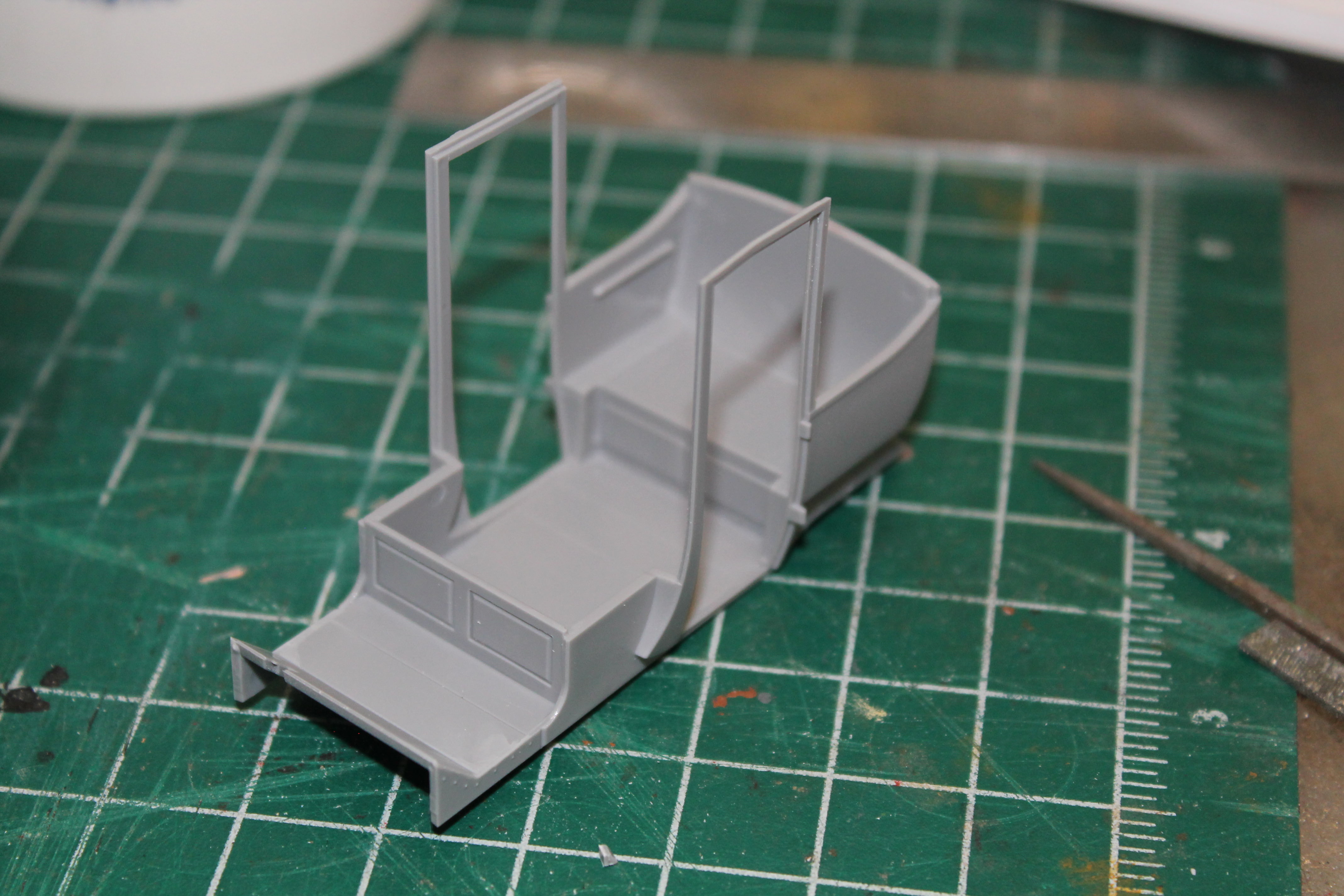
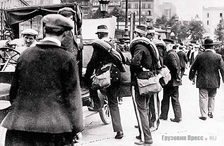
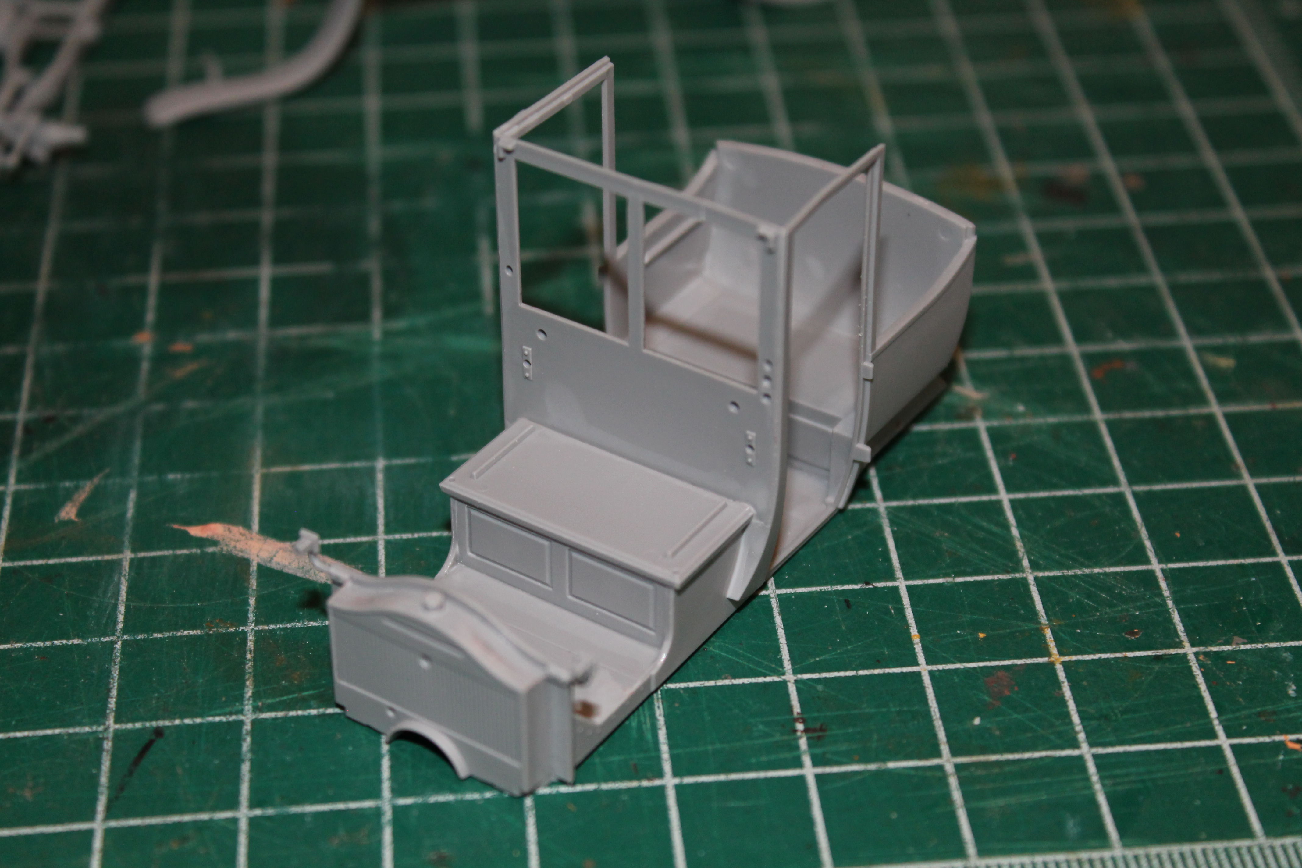
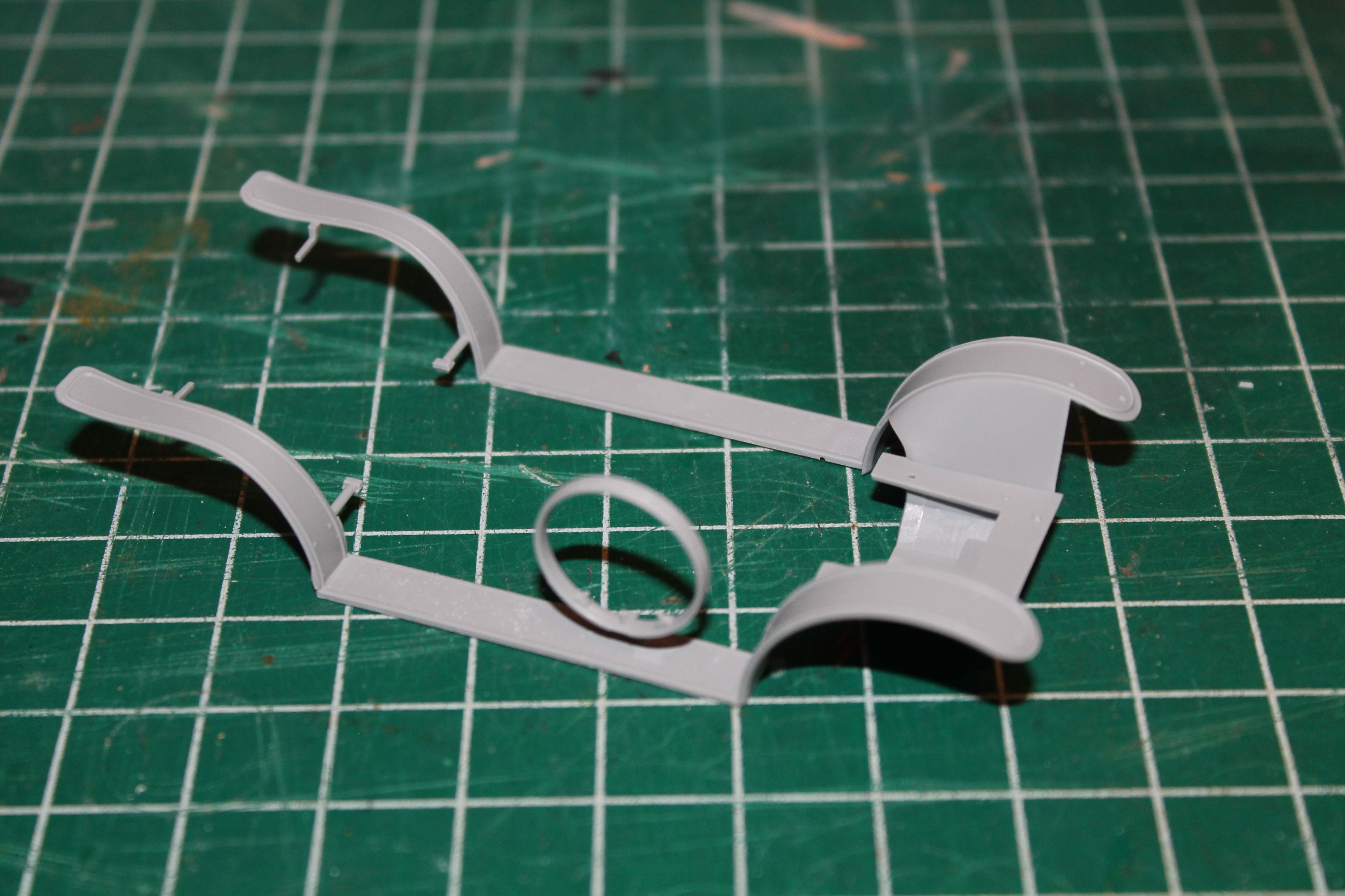
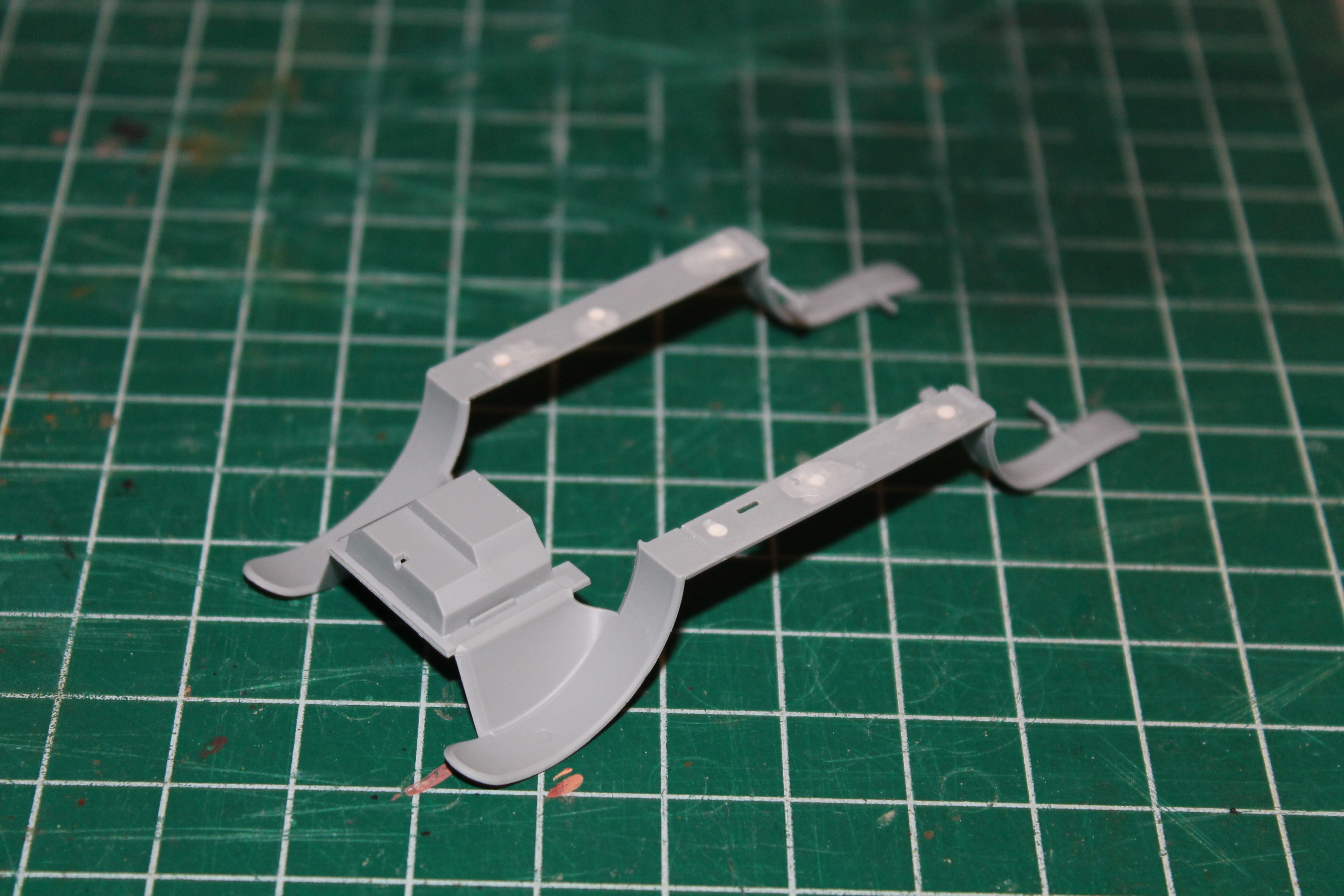
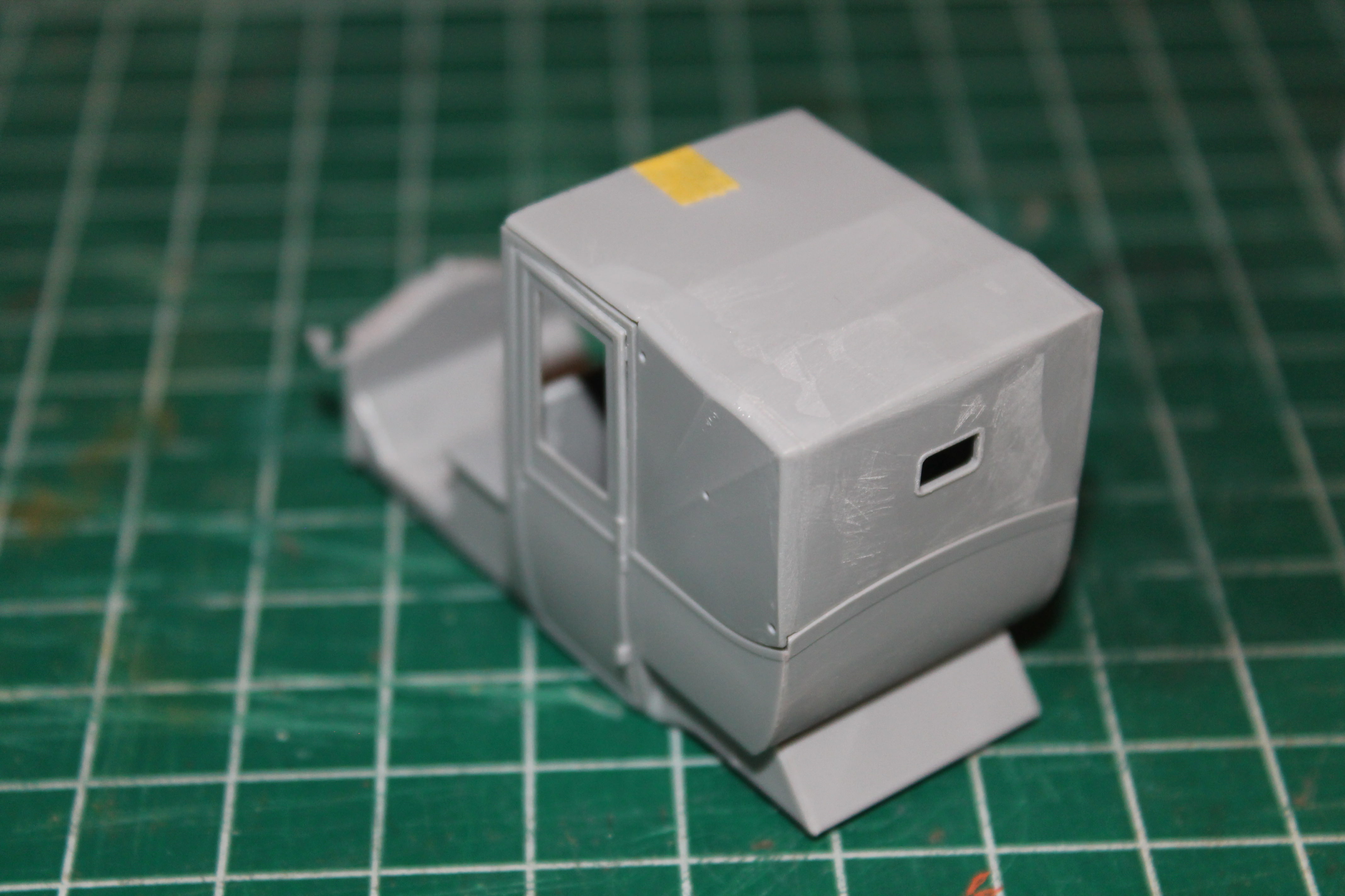
I then went on to the driver's roof, again deviating from the instructions. In Step 48, you're supposed to attach one of the roof supports (B5) to the body, at an angle. In Step 51, you attach the other support (B2) to the roof (B7). Then join the two together in the next step. I thought it better to assemble all three pieces together as one sub-assembly. I wasn't sure from looking at the drawing, exactly how B2 was supposed to fit. Turns out the front edge gets cemented to the roof, with the sides parallel to the roof's edge. The sides are left free floating, with a bit of a gap between them and the roof. The other support (B5) has a pin that fits into a hole in the roof and it butts up against the ends of B2.
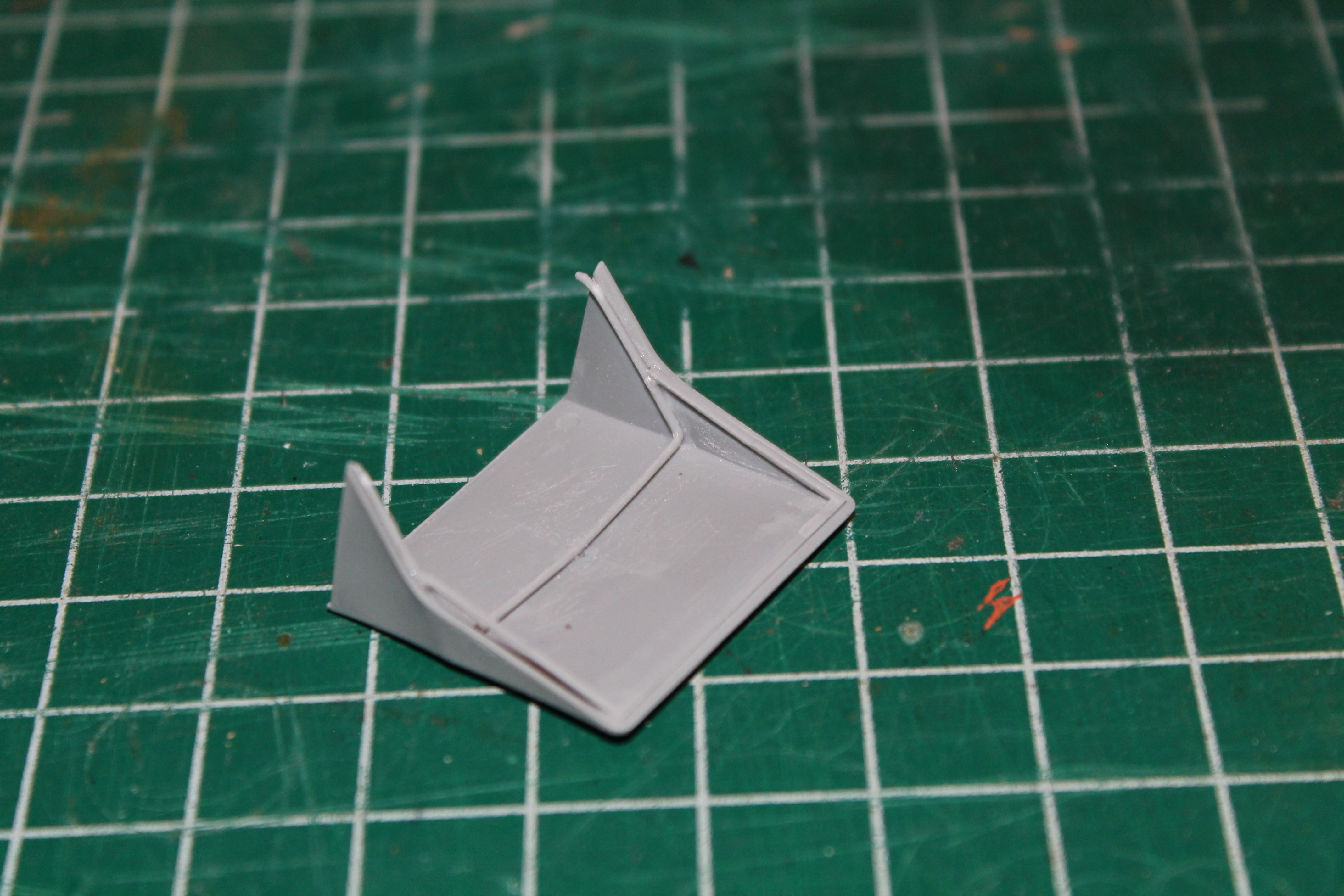
I test fitted this assembly and it lines up perfectly. I feel doing it this way made it much easier to line everything up, and lessened the chance of making a mistake. Also note, the supports are quite fragile and care must be used in removing them from the sprue. I used a sharp chisel-type Xacto blade to separate them from the sprue with no problem. But then broke one trying to clean up any burrs. I found it easier to clean the parts up after assembling them together, rather than separately. Well, that's all for now. A few more sub-assemblies, then it's off to the paint shop.

Al