There has been a couple of reviews already on the web. There has also been a very good build of the kit where the builder carefully cuts away the engine cover to be to show off the engine. I will be doing that in this build also.
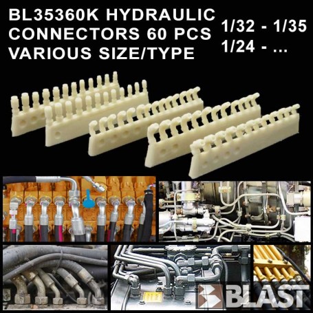
After going thru the instructions a couple of times, I came to the conclusion that I will be doing this build in 4 major sub-assemblies, the engine/hull, cab, out riggers and back hoe, and the bucket with arms. I will be adding a majority of the missing hydraulic hoses and adding more and/or missing detail from the cab since you have two big windows you can see through.
Upon opening the box, I could see right away that there is a lot of punch marks and yes, a lot of them can be seen. The first glance through the instruction booklet, I noticed a couple of major missing items other than the hydraulic hoses. In the cab, there is no roof or wall detail, no AC unit and instrument cluster located on the right wall and no back hoe controls. This will be covered when I do the cab sub-assembly.
The cab sub-assembly looks like it is going to take more work than the others. So for know, I am going to start on the out riggers and back hoe.
Step 10 and 12 cover the out riggers and back hoe. The out riggers went together with out no issues, just filling punch marks and sanding seems.


As you can see from the pictures, I deviated from the instructions a bit to aid in the build. I added five pieces from the back hoe step to the out rigger step. Parts A27, A32, and A37 are supposed to be sandwiched between parts B28 and B31 and then attached to the out riggers. Because of the ugly seem and possibly gluing the pins of the back hoe to parts B28 and B31, I chose to leave them off the back hoe and drill out the pins. I will add pins with Evergreen rod stock.

There is one instruction correction for step 12. Part A32 is not labeled in the instructions, but it is shown in it's correct position. Start with putting B31 and B28 together along with hydraulic tube D52. Glue B50 and B51 together and before moving on, fill and sand the large seem. After gluing B55 and B56, again, fill and sand the big seem. To have parts B60, A23, and A22 kept moving, just snap in place and do not glue. The instructions have you not place glue on three locations of these parts, but to make workable, glue is NOT to be used at all on these parts.


Remember, careful gluing and the out riggers and back hoe will move.
Next update will be adding the hydraulic hoses to the out riggers and back hoe. After that I will be moving on the the bucket sub-assembly.