Hi All!
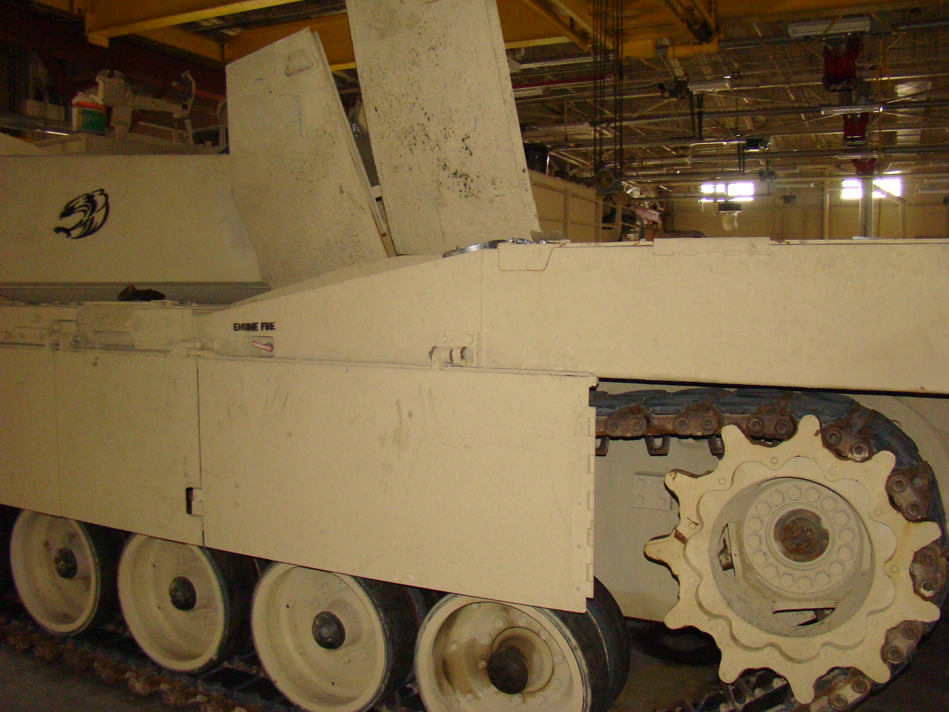
Sorry, this may be a little bit obvious but I wanted to make sure... The Drive Wheel for the Dragon Abrams I am working on looks like this:
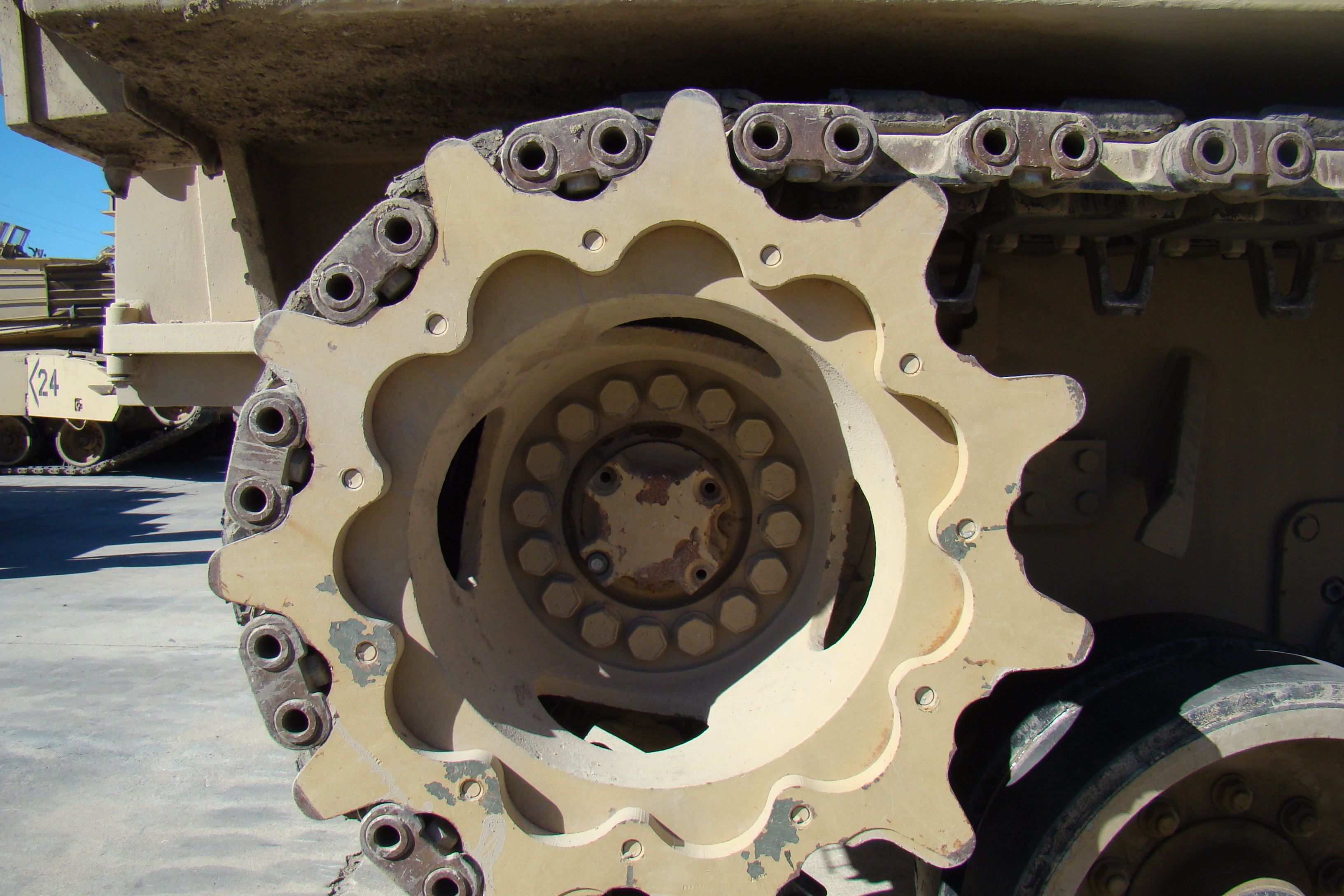
Looking online I have found the following photo of the drive sprocket:
I am assuming that dragon has the wrong shape around the mud clearing holes and I need to correct it, right? I just want to make sure that Dragon doesn't know something that I don't before I get into the work of fixing it up.
Thanks guys
Mike
Hosted by Darren Baker
Abrams Drive Wheel - Help Please
mmarchioli
Florida, United States
Joined: March 18, 2008
KitMaker: 173 posts
Armorama: 168 posts
Joined: March 18, 2008
KitMaker: 173 posts
Armorama: 168 posts
Posted: Sunday, July 05, 2020 - 12:19 PM UTC
18Bravo
Colorado, United States
Joined: January 20, 2005
KitMaker: 7,219 posts
Armorama: 6,097 posts
Joined: January 20, 2005
KitMaker: 7,219 posts
Armorama: 6,097 posts
Posted: Sunday, July 05, 2020 - 03:00 PM UTC
Here's another you can look at. The back edge of each hole appears almost straight.
And one of the ones I sent to MENG several years ago:
mmarchioli
Florida, United States
Joined: March 18, 2008
KitMaker: 173 posts
Armorama: 168 posts
Joined: March 18, 2008
KitMaker: 173 posts
Armorama: 168 posts
Posted: Monday, July 06, 2020 - 06:03 AM UTC
Thanks Robert.
I updated the picture a little, I'm not sure if I was clear in my original post. I'm curious if these "cutouts" (red arrows) are really present on some tanks, or do I need to fill these in and re-contour the parts?
I assume I need to fix these as I can't really find an example of a drive sprocket anywhere that looks like this. Just looking for a consensus.
Thanks
Mike
Frenchy
Rhone, France
Joined: December 02, 2002
KitMaker: 12,719 posts
Armorama: 12,507 posts
Joined: December 02, 2002
KitMaker: 12,719 posts
Armorama: 12,507 posts
Posted: Monday, July 06, 2020 - 06:45 AM UTC
I guess Pawel Krupowicz's article should help with your question...
https://vodnik.net/pages/M1A2comp/m1a2comp_02.htm
H.P.
https://vodnik.net/pages/M1A2comp/m1a2comp_02.htm
H.P.
tnker101
New York, United States
Joined: November 30, 2007
KitMaker: 117 posts
Armorama: 115 posts
Joined: November 30, 2007
KitMaker: 117 posts
Armorama: 115 posts
Posted: Monday, July 06, 2020 - 07:21 AM UTC
To be continued arrggh..lol was into the article because I'm build a MENG M1A2 Tusk.
TankManNick
California, United States
Joined: February 01, 2010
KitMaker: 551 posts
Armorama: 543 posts
Joined: February 01, 2010
KitMaker: 551 posts
Armorama: 543 posts
Posted: Monday, July 06, 2020 - 07:27 AM UTC
To me it looks like Dragon went with what would work in a regular 2-part mold (i.e. not slide-molded). They could have gone multi-part, but they didn't. Break out the putty!
RobinNilsson
TOS Moderator
Stockholm, Sweden
Joined: November 29, 2006
KitMaker: 6,693 posts
Armorama: 5,562 posts
Joined: November 29, 2006
KitMaker: 6,693 posts
Armorama: 5,562 posts
Posted: Monday, July 06, 2020 - 08:04 AM UTC
Molding restrictions.
Set the outer part on a table, bolt ring downwards and then view it from straight above.
The lower mold (the table) comes up inside the holes and the upper mold (your view) comes down from above and meets the lower mold in the holes.
The lower mold slides out nicely since the inside of the hub is smooth, the upper mold needs these coutouts to avoid getting caught by the holes.
Look at the edges left behind around the holes by the edges where the molds meet.
This has nothing to do with slide molds, just plain simple two part molds which require suitable release angles. The holes would be undercuts and trap the mold.
Withe slide molds it would require one sliding pin for each hole (i.e 4 pins) and the hubs would need to be on their own little sprue for that.
Plasticard and some putty will solve this.
HeavyArty
Florida, United States
Joined: May 16, 2002
KitMaker: 17,694 posts
Armorama: 13,742 posts
Joined: May 16, 2002
KitMaker: 17,694 posts
Armorama: 13,742 posts
Posted: Monday, July 06, 2020 - 12:41 PM UTC
Short answer, yes, they need to filled in and reshaped. It is due to the mold design and not present on the actual drive sprockets.
mmarchioli
Florida, United States
Joined: March 18, 2008
KitMaker: 173 posts
Armorama: 168 posts
Joined: March 18, 2008
KitMaker: 173 posts
Armorama: 168 posts
Posted: Monday, July 06, 2020 - 03:15 PM UTC
You all pretty much confirmed what I thought. Thanks very much for the help!
Thanks
Mike
Thanks
Mike