Following up on the inbox review of Vespid's new A34 Comet tank here, this will show the build. The instructions and sprue shots can be viewed on the review page.
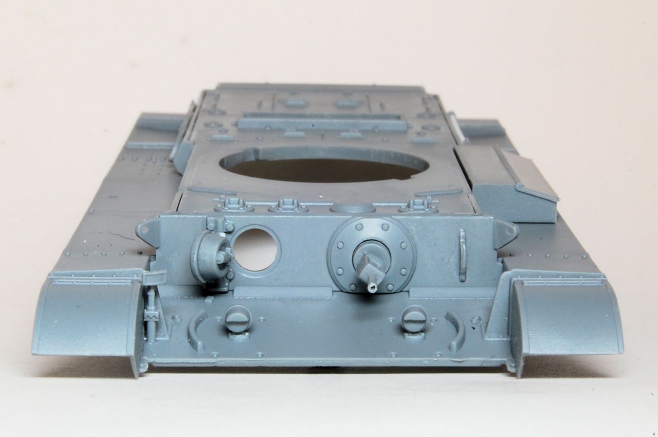
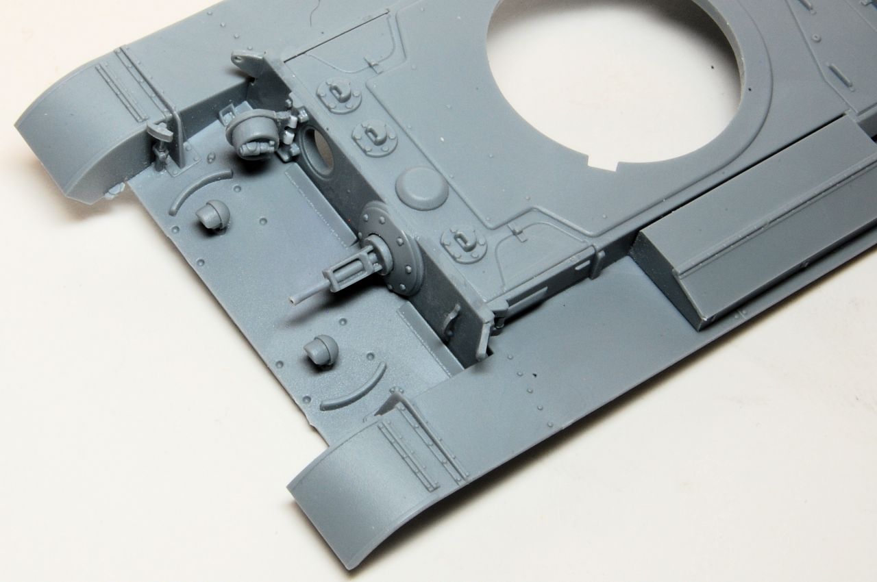
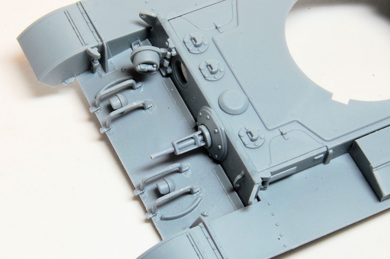
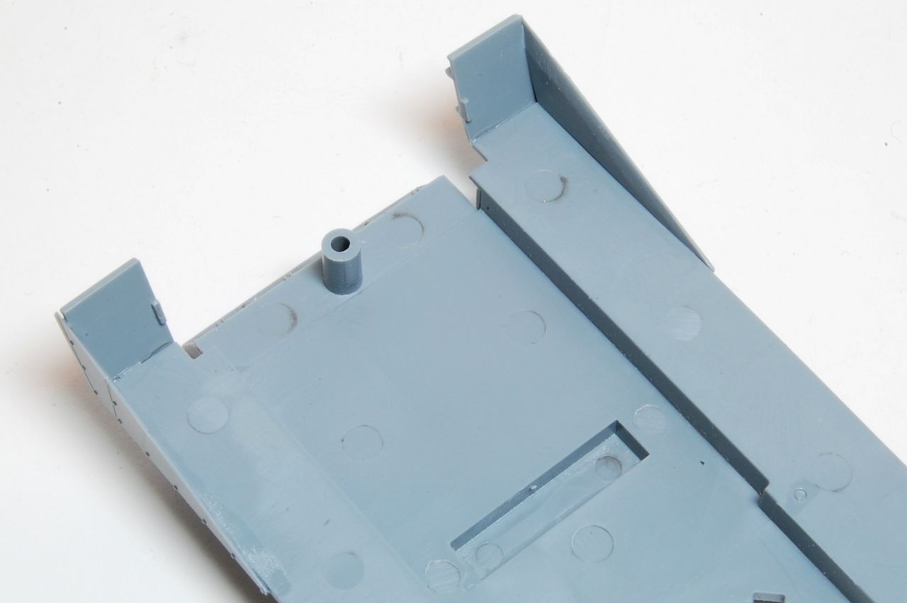
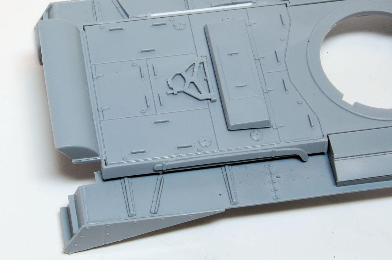
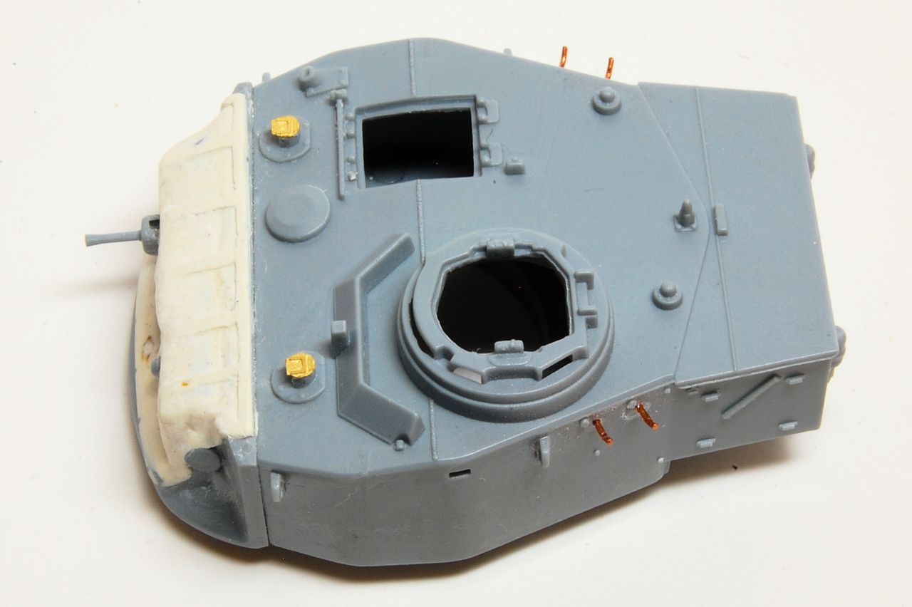
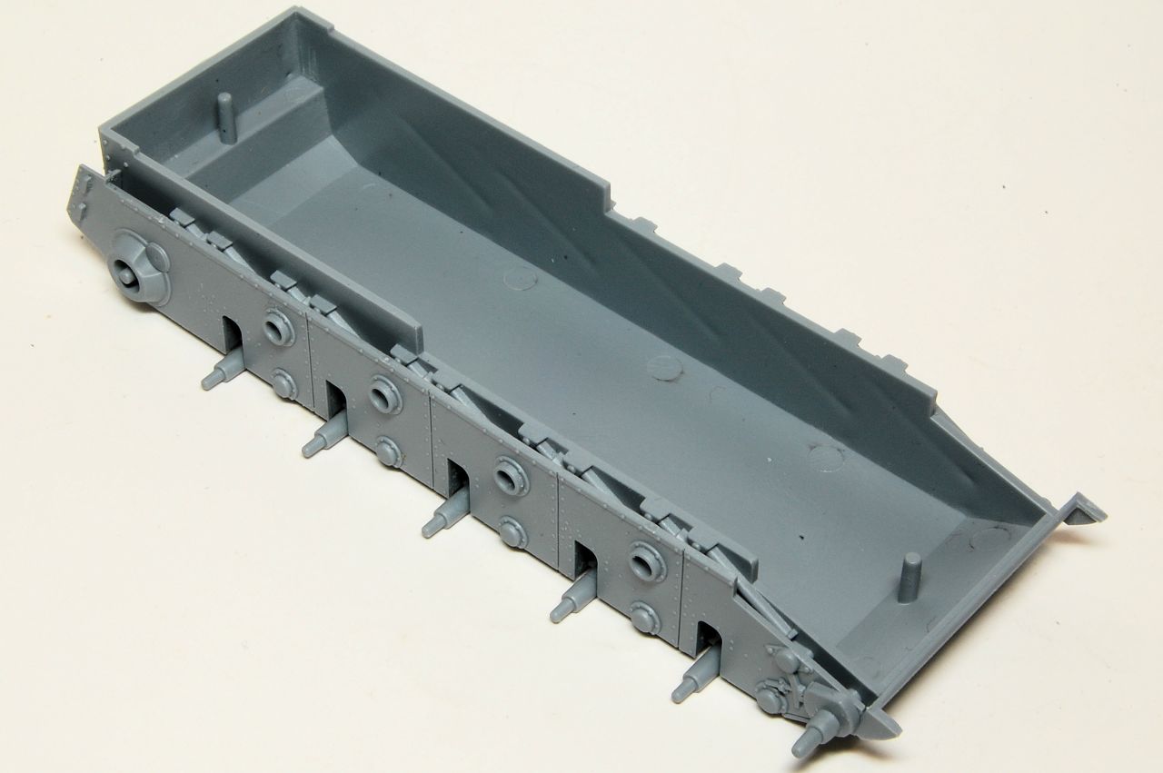
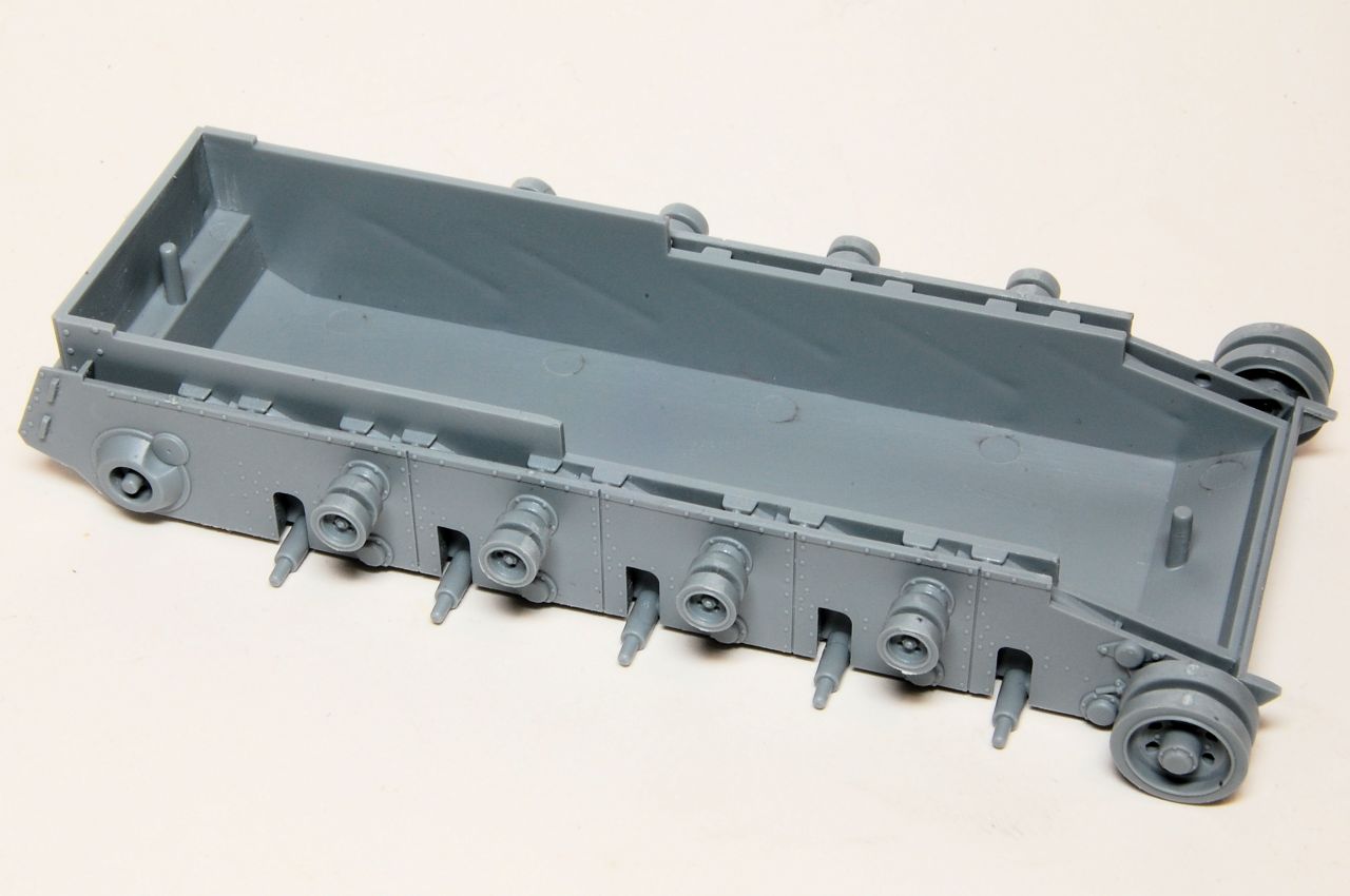
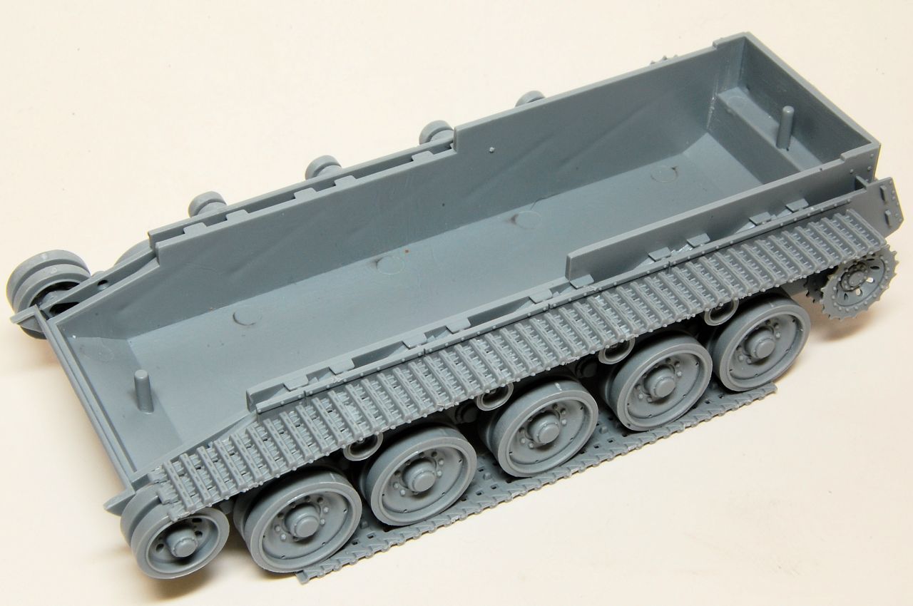
Starting with the hull, the outer side walls are added over the internal Christie shocks and axles. This is a nice authentic design touch, though I suspect none of it will be visible if the model is fully built as an intact tank. Fit is perfect, needed a few dots of cement to make sure it is securely fixed all the way along.
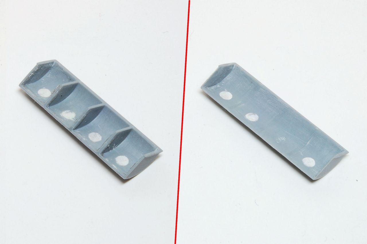
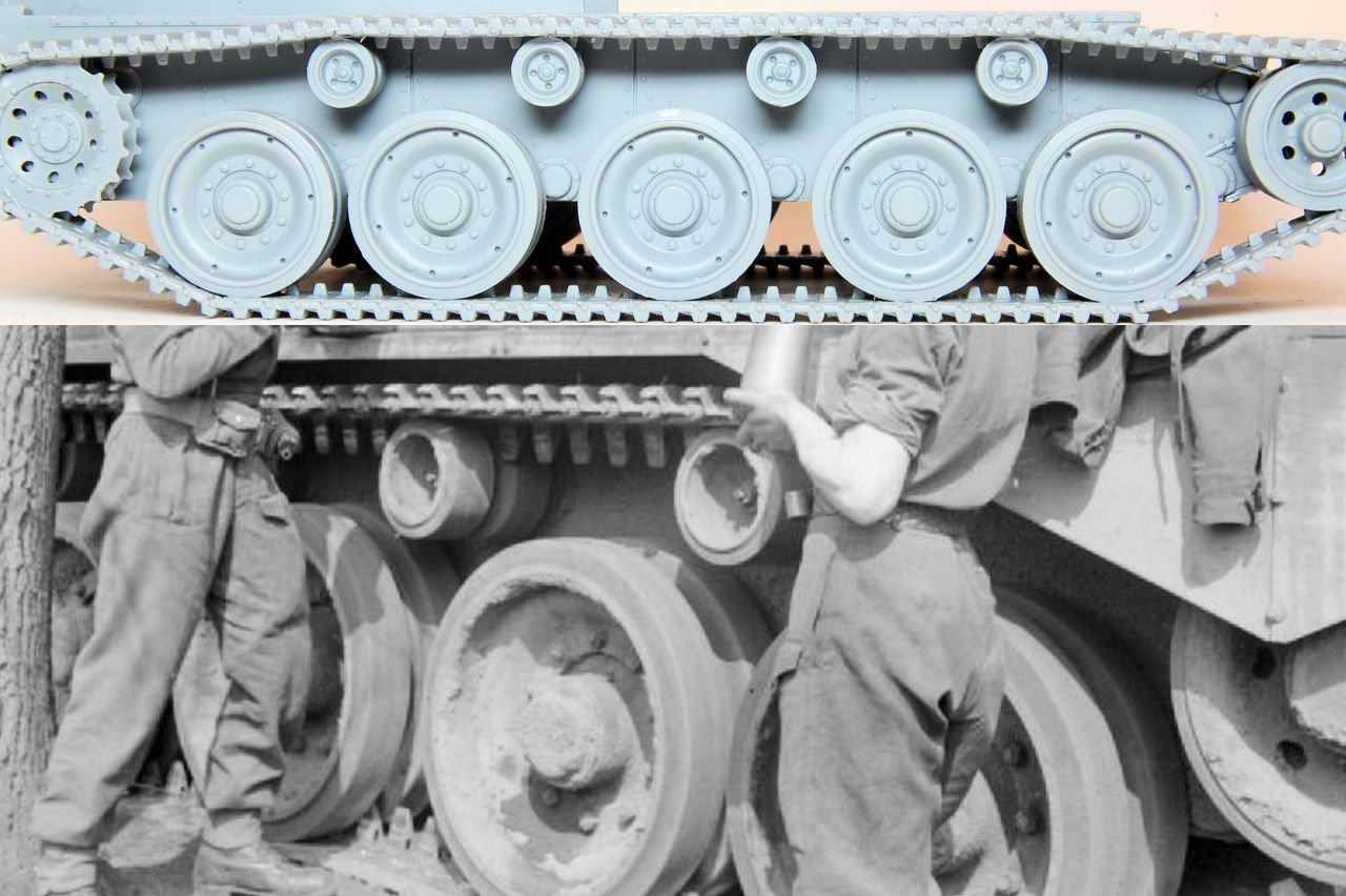
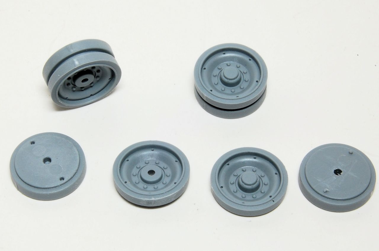
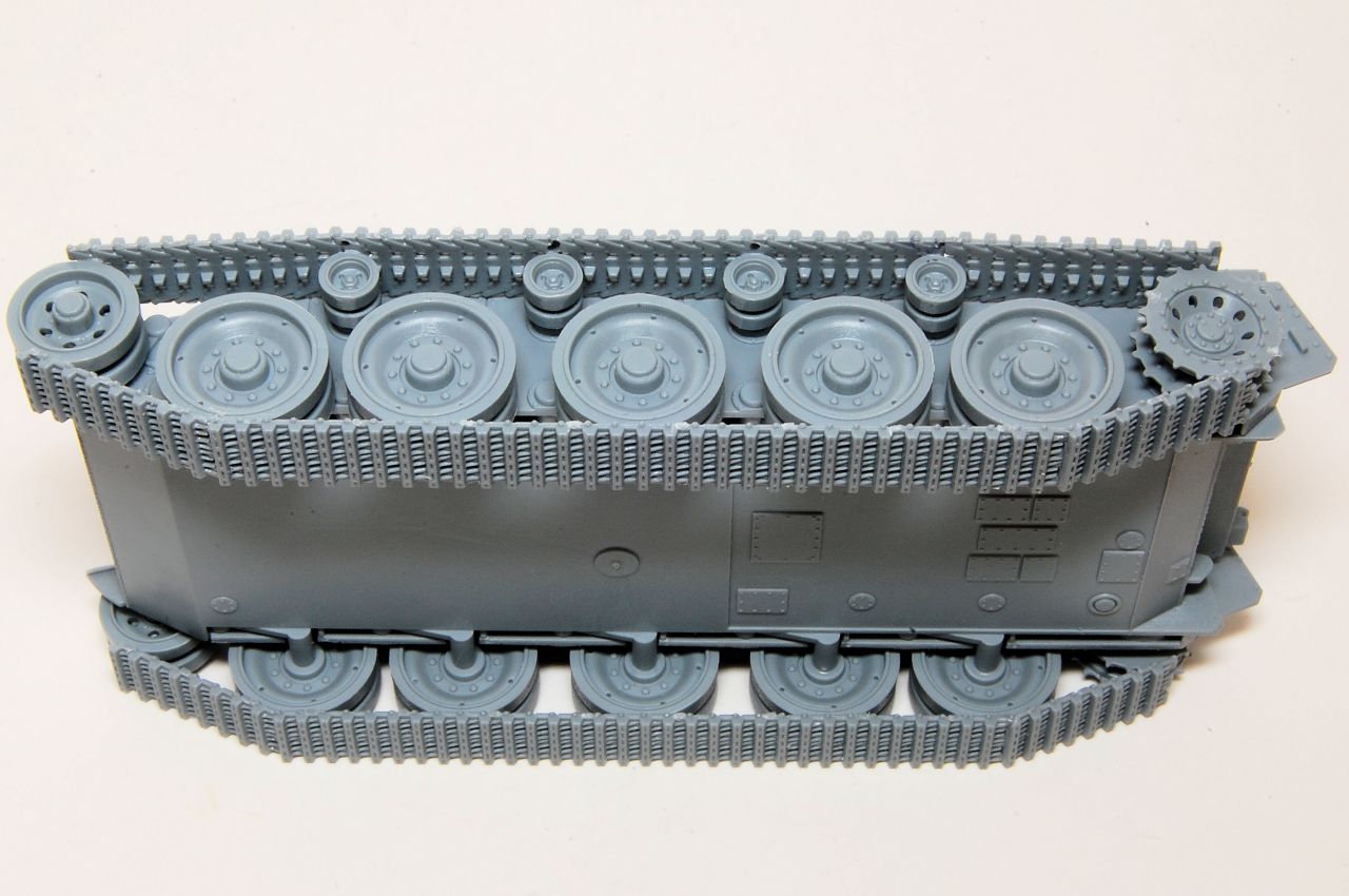
The road wheels go together without any fuss being quite chunky, just the normal cleaning up of sprue tags and a small amount of ejector mark on the mating face. Only five per side as well - a nice change from some of the piddly fiddly wheels I've had to deal with recently.
Return rollers went on easily enough, helped by the sprue attachment being the axle end.
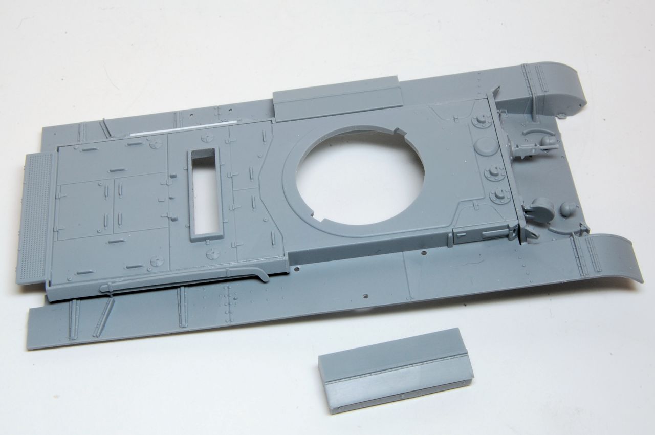
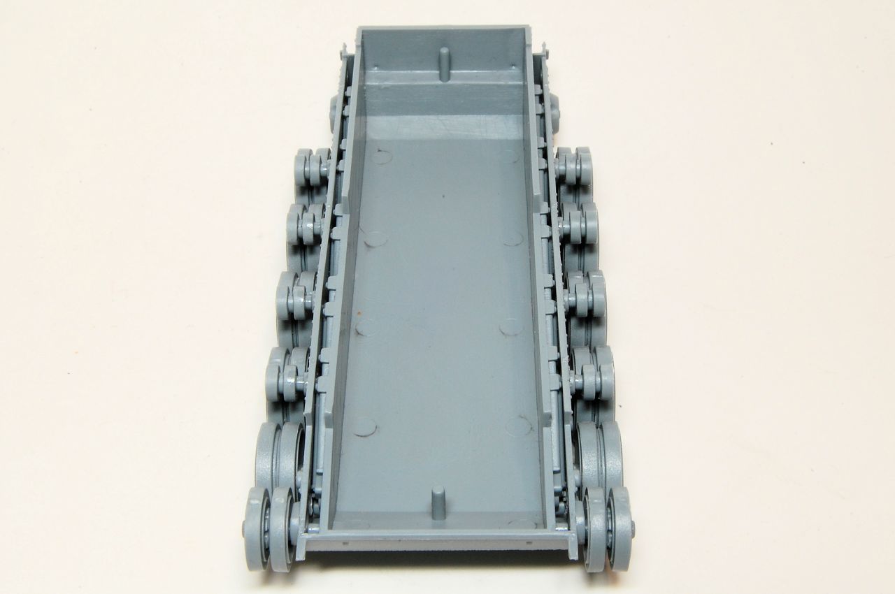
Then the roadwheels, and the idler:

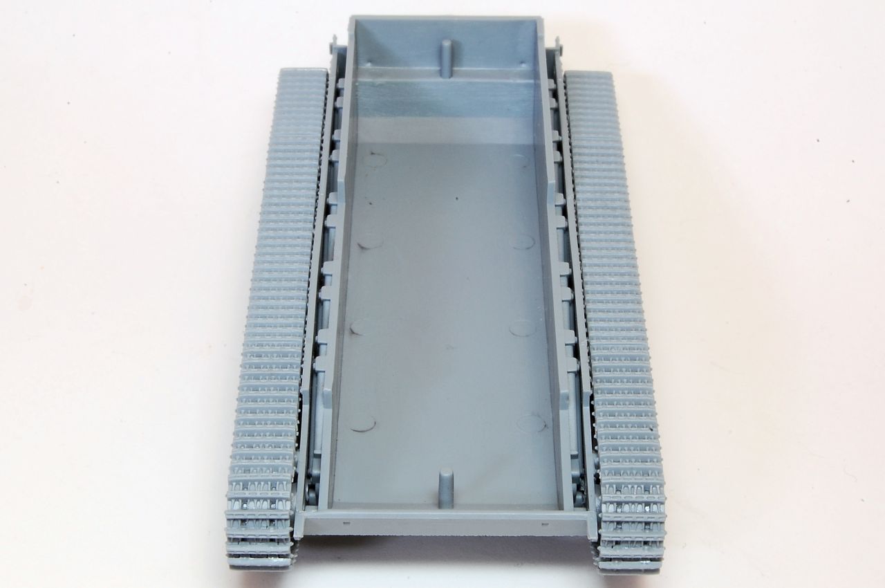
Main thing required is to make sure they all line up straight:
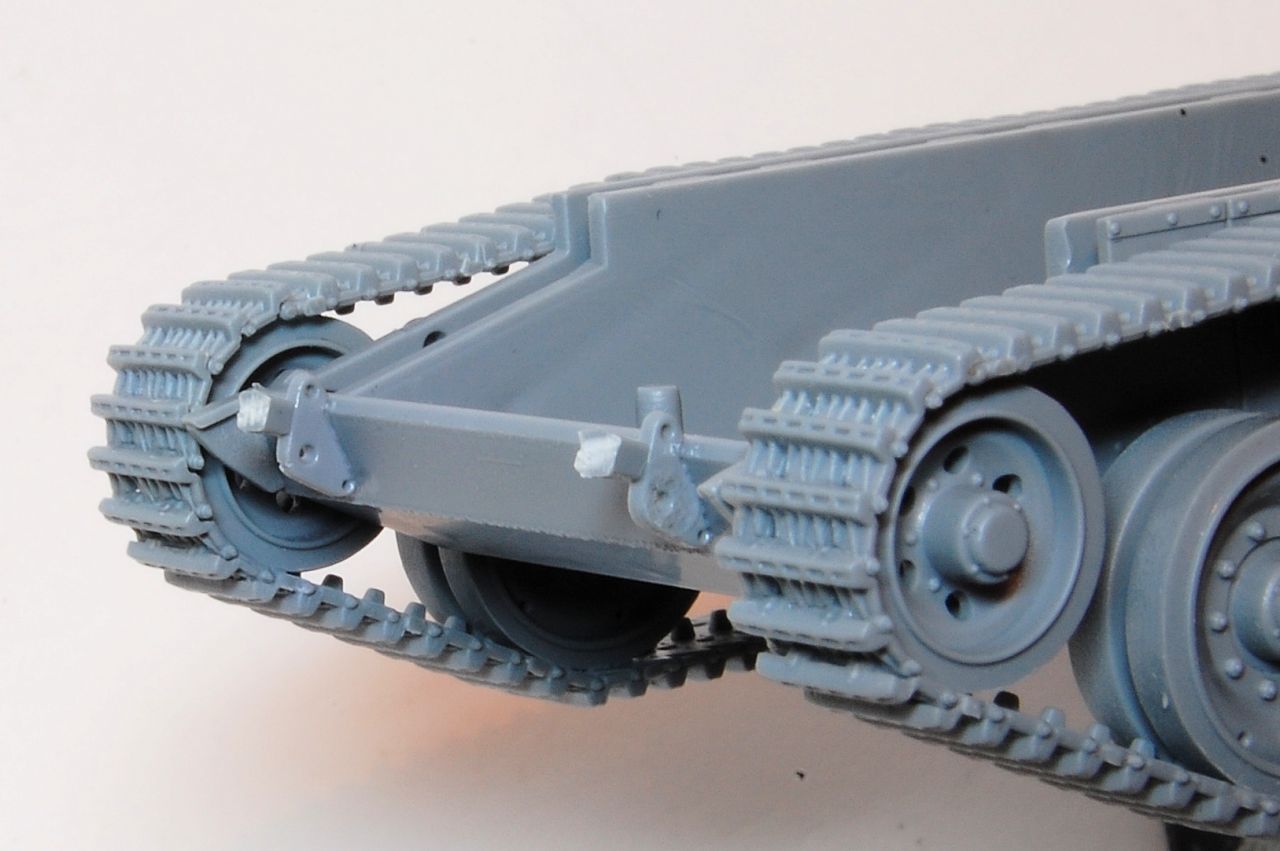
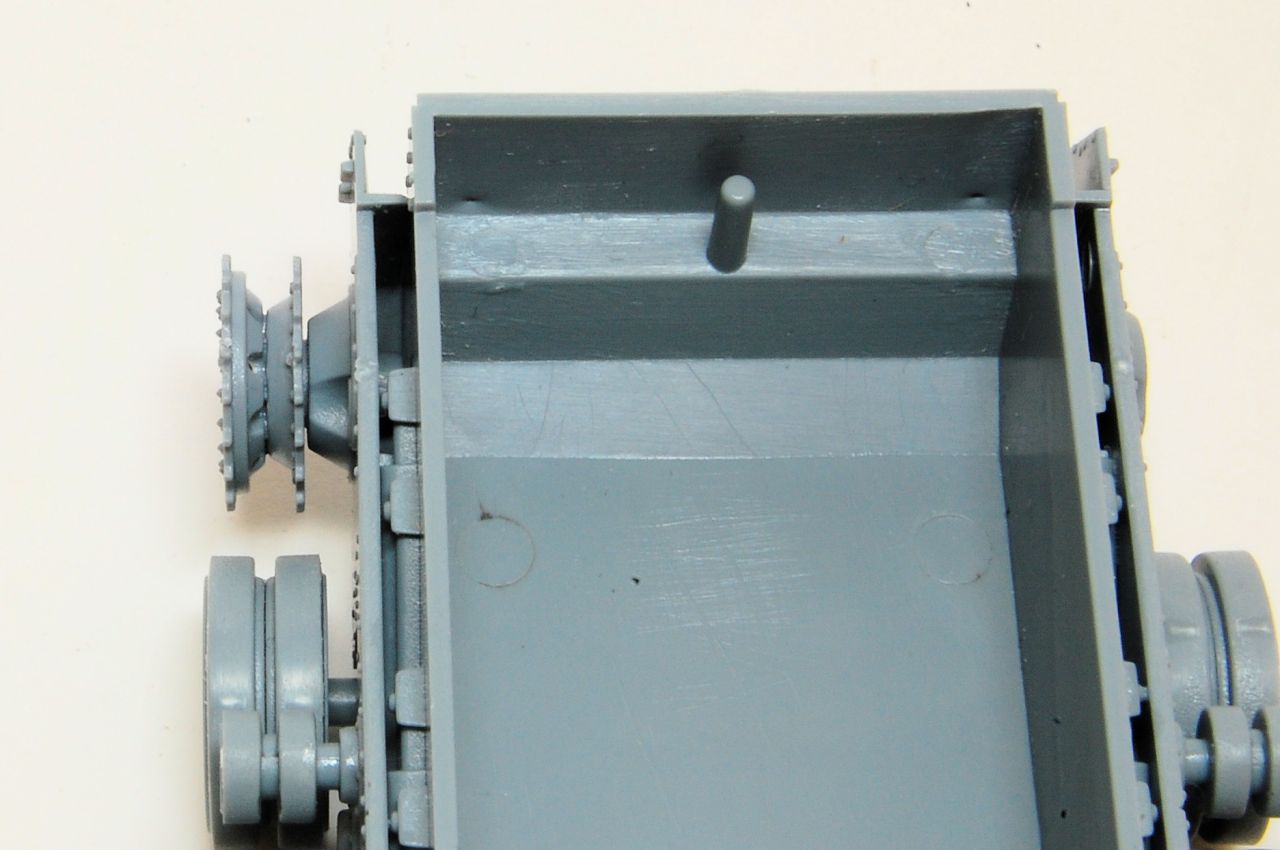
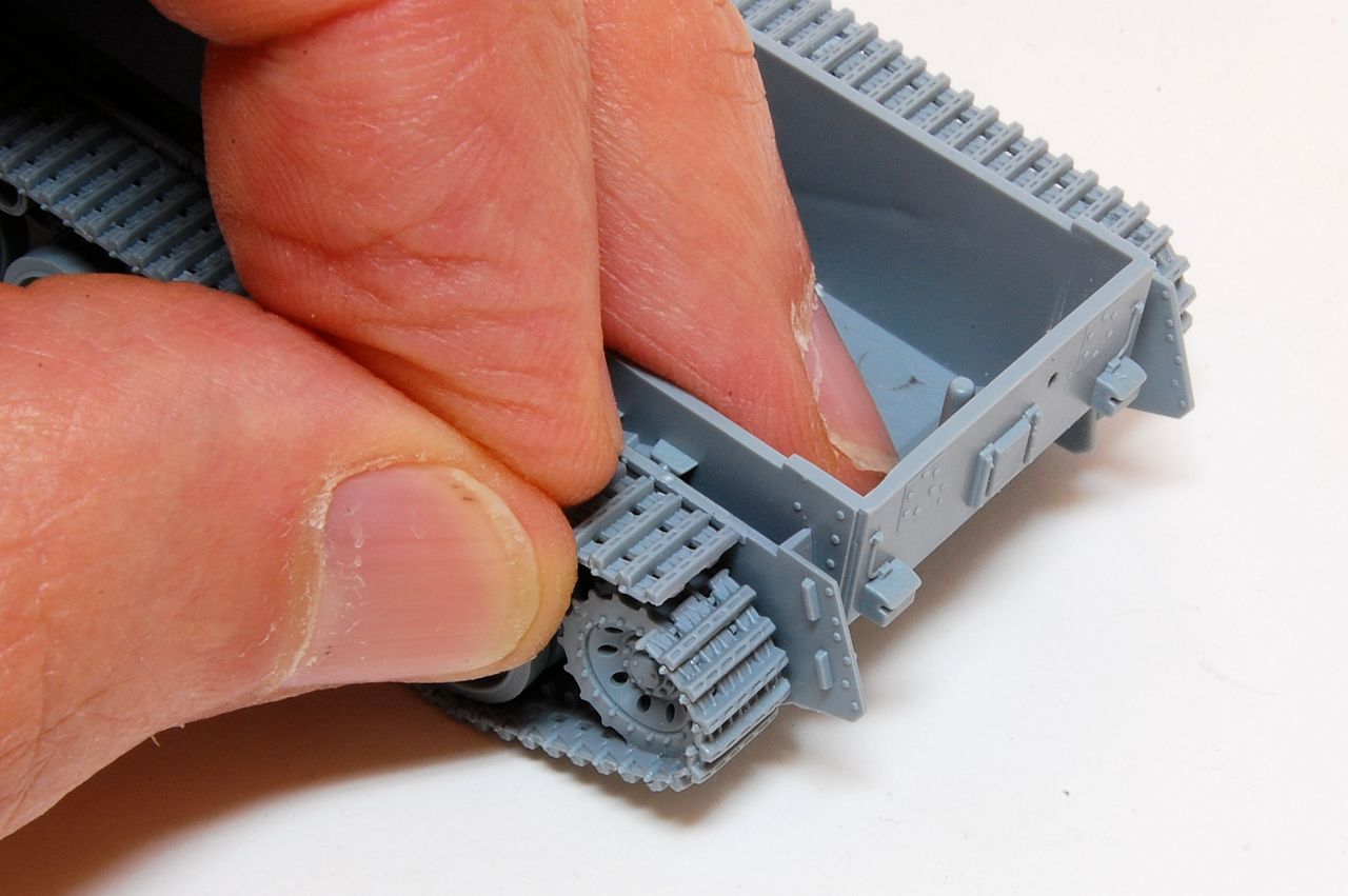
Sprockets join together easily, and the attachment point to the hull is very solid, allowing it to stay in place without cement, so it can be rotated to align with the tracks. At first the idler stood away from the hull:
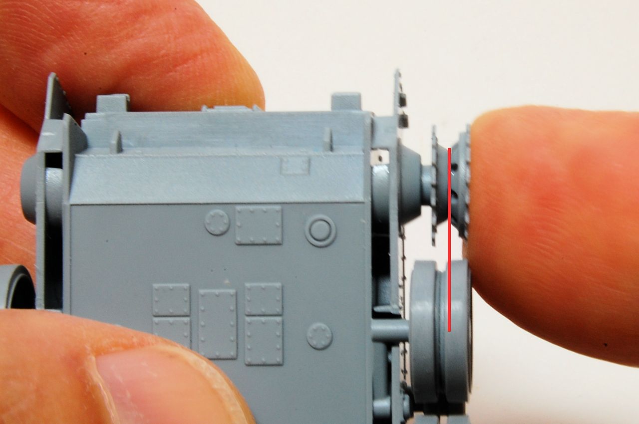
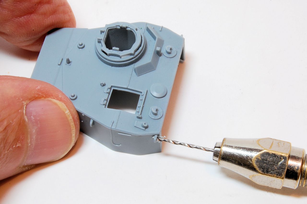
A combination of drilling the hole on the wheel, expanding the location point on the hull and shortening the axle stub resulted in it being possible to align with the roadwheels:
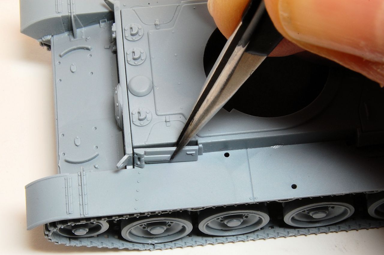
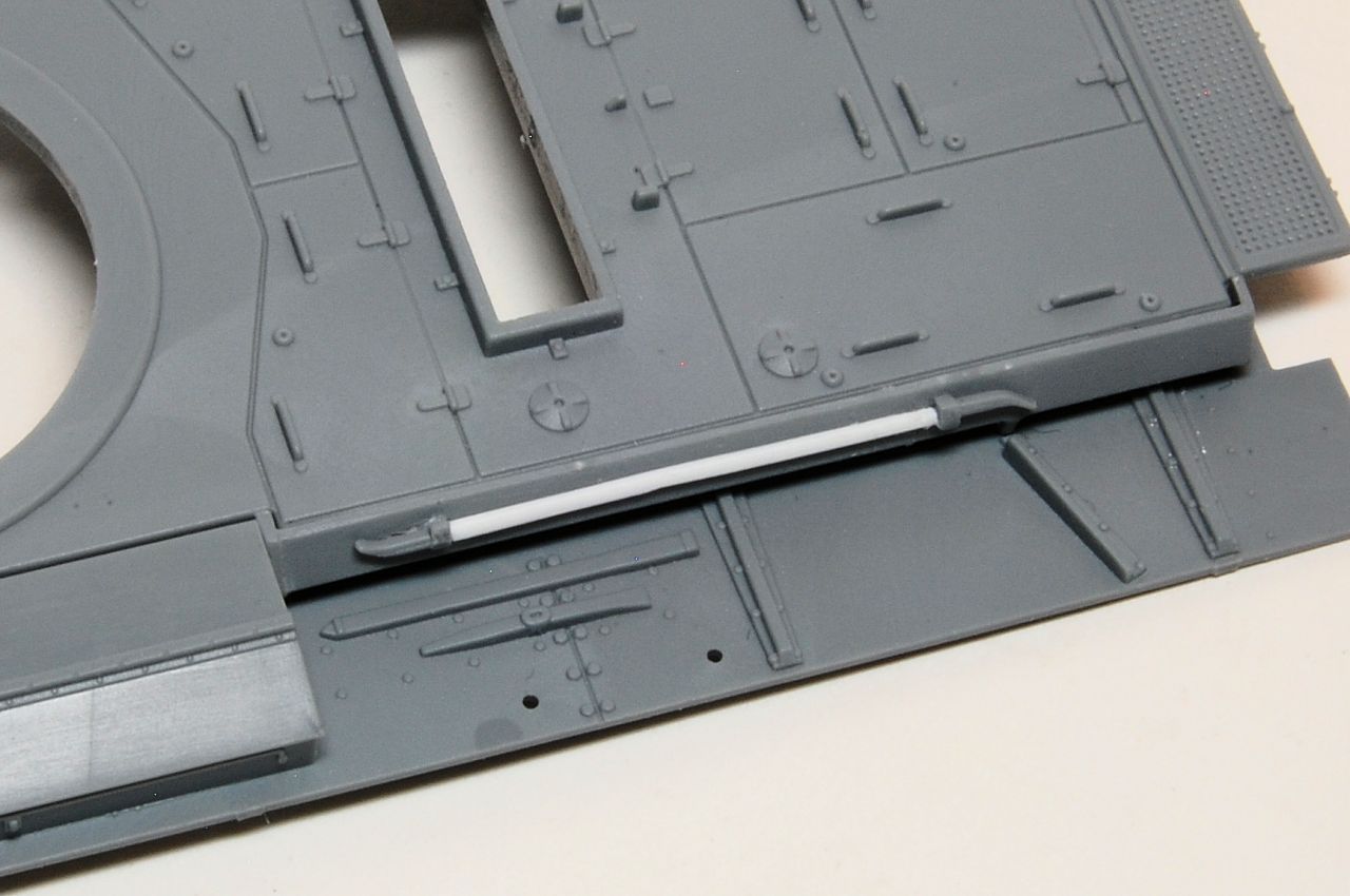
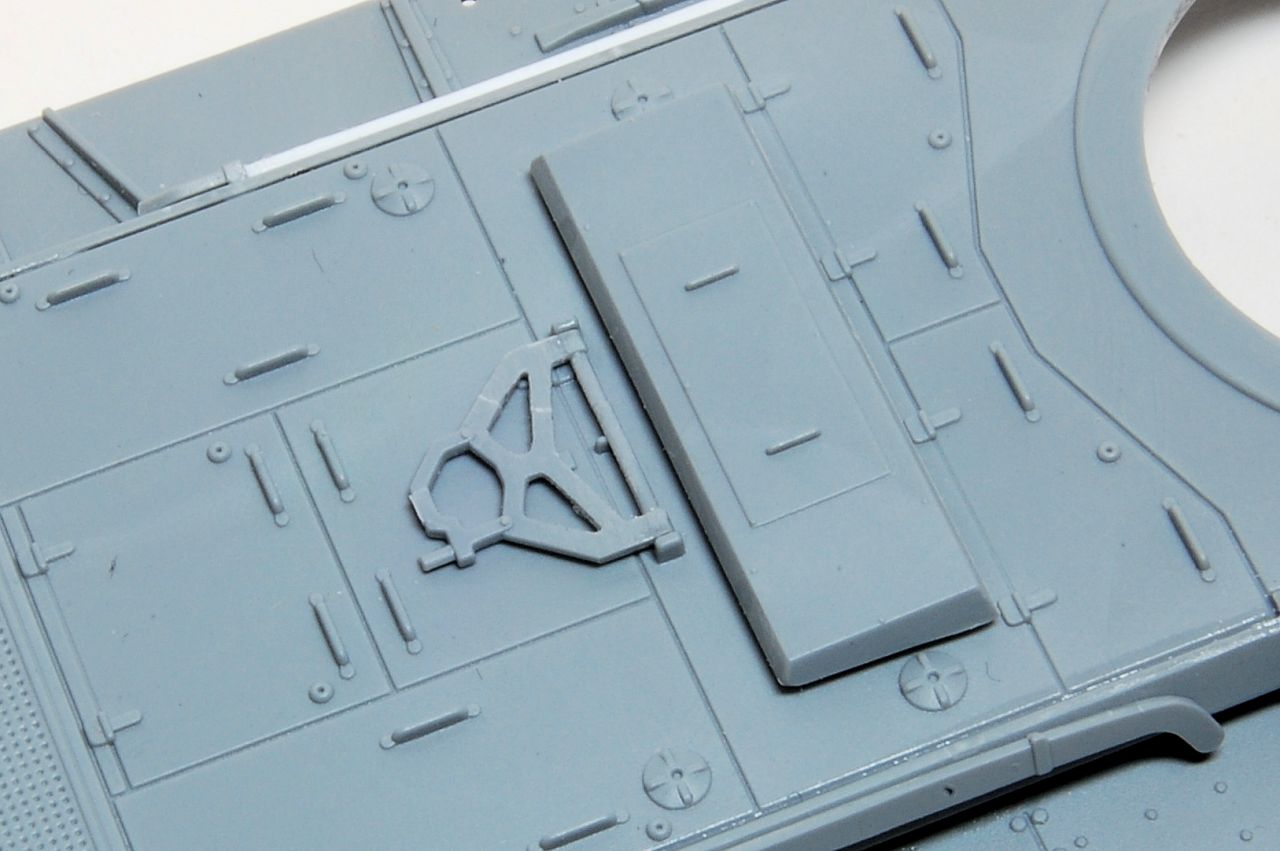
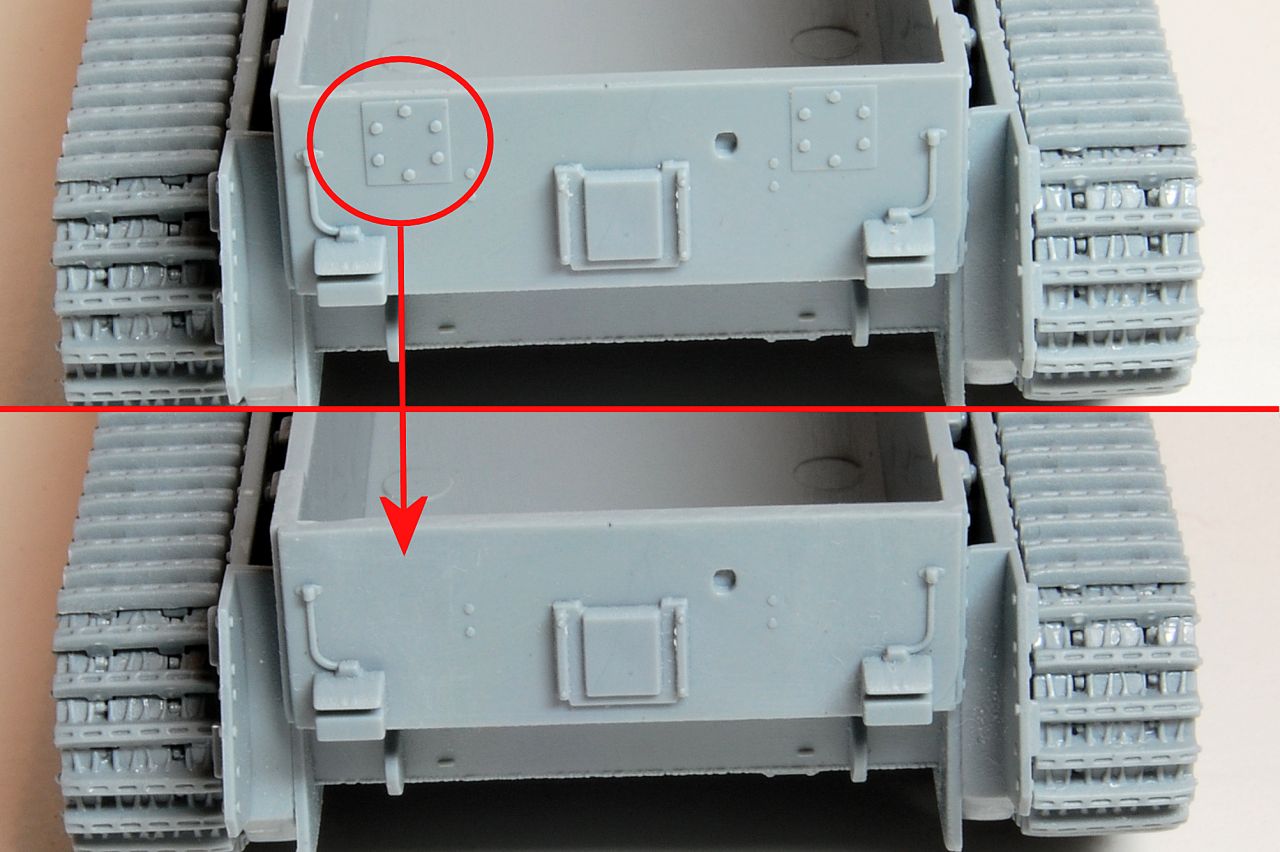
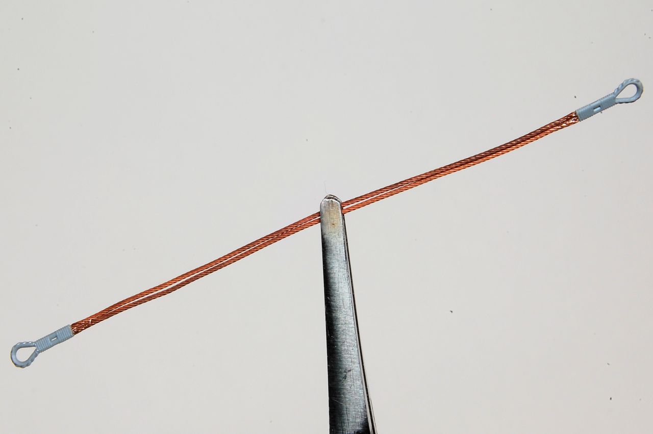
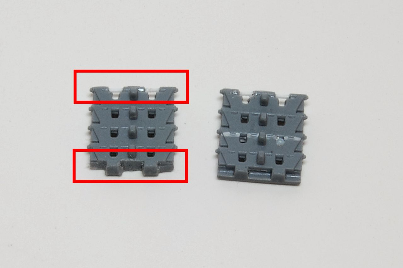
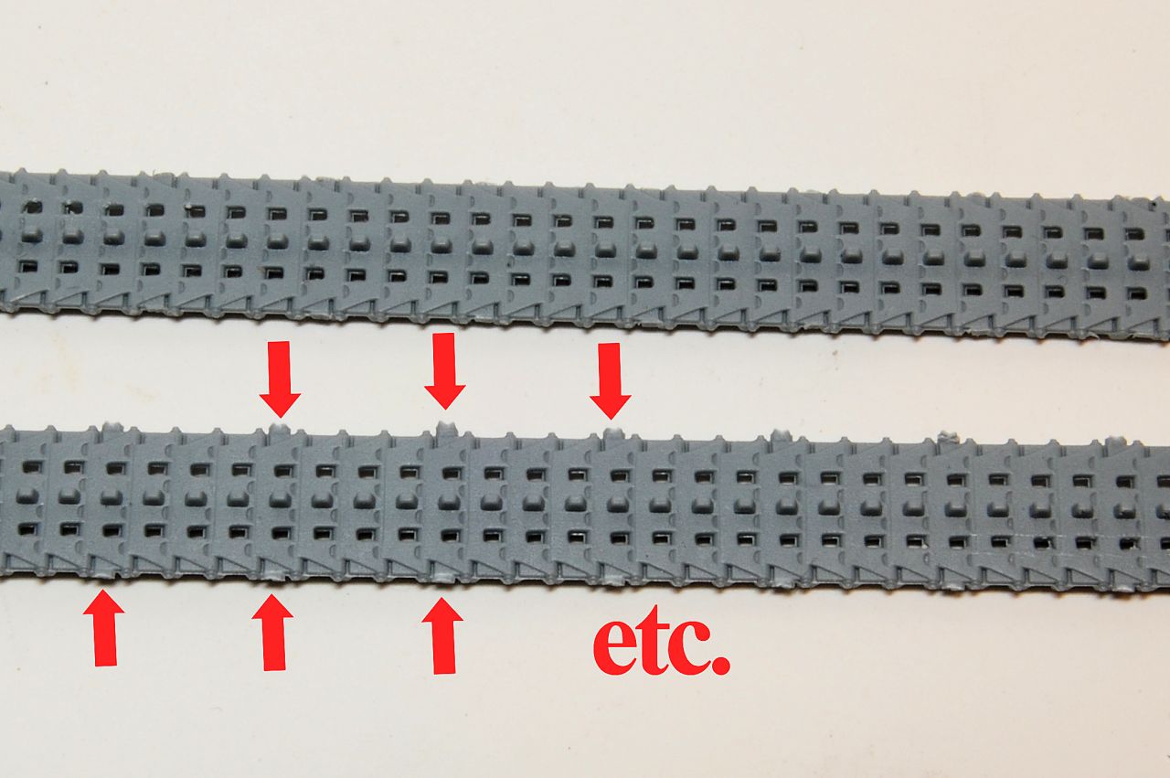
Slightly more clean up effort is required with the link and length tracks. The sprue attachments are quite numerous and are in between the track pins. That's good but makes removing the sprue tags quite tricky. I used a newish pointed blade inserted almost vertically down between the track pin and the tag, the blade would hit the cutting mat before it could go too far and risk slicing right through the adjacent track pin. I did manage to lose a couple
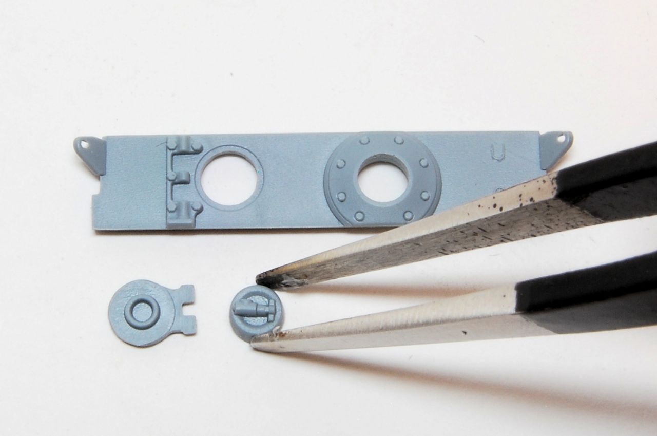
however before I sussed that method. Photo shows before (below) and after (above) that initial trim:
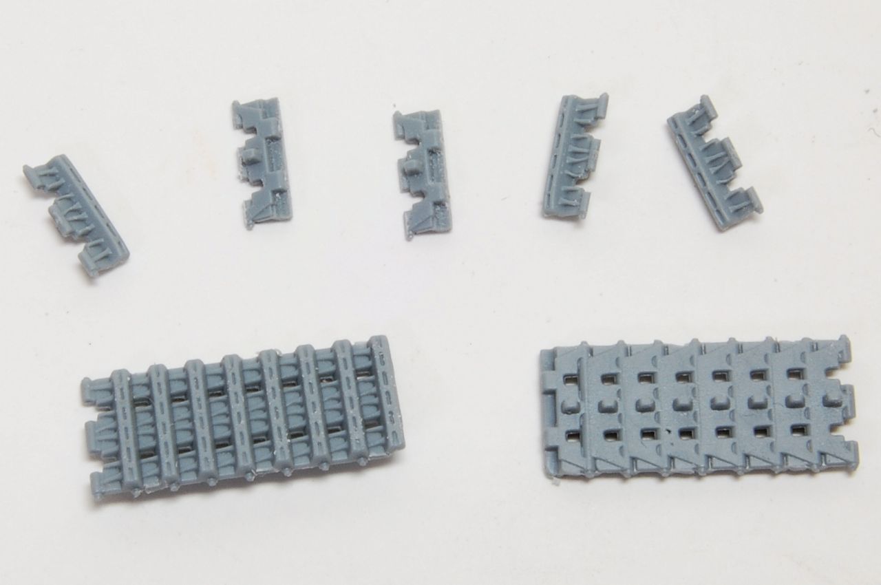
There are some single links as well, which are easier to deal with as the attachment is on the long sides:
The instructions don't specify the assembly order and I went ahead with all the long sections, which on reflection was a mistake. I suggest starting with the bottom section, then the shorter lengths between the road wheels and the idler and sprocket, then the single links, starting at the bottom, then finally adding the top length. This will avoid the situation where the final single link either doesn't span the final gap, or is too big to squeeze in.
Anyway, here are the bottom and top runs in place:
Then the lengths up to the idler and sprocket:
I got away with it on the left track and the final link fitted exactly (tick), but on the right track the gap wasn't correct (cross).
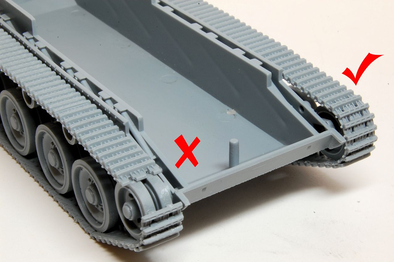
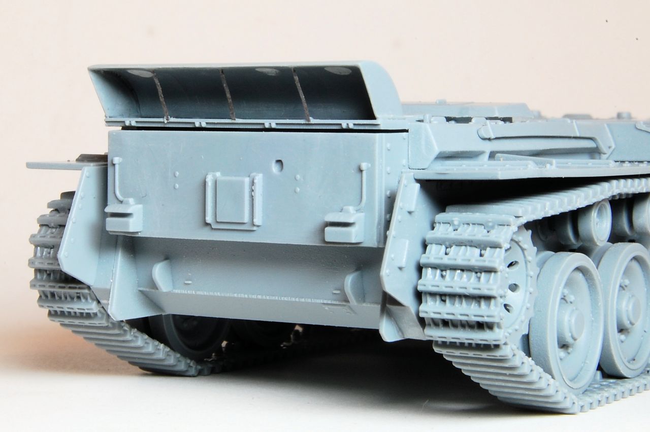
However, the small gap that was left would be completely hidden by the front side track guard, and there is a similar guard at the back if the same siuation arises.
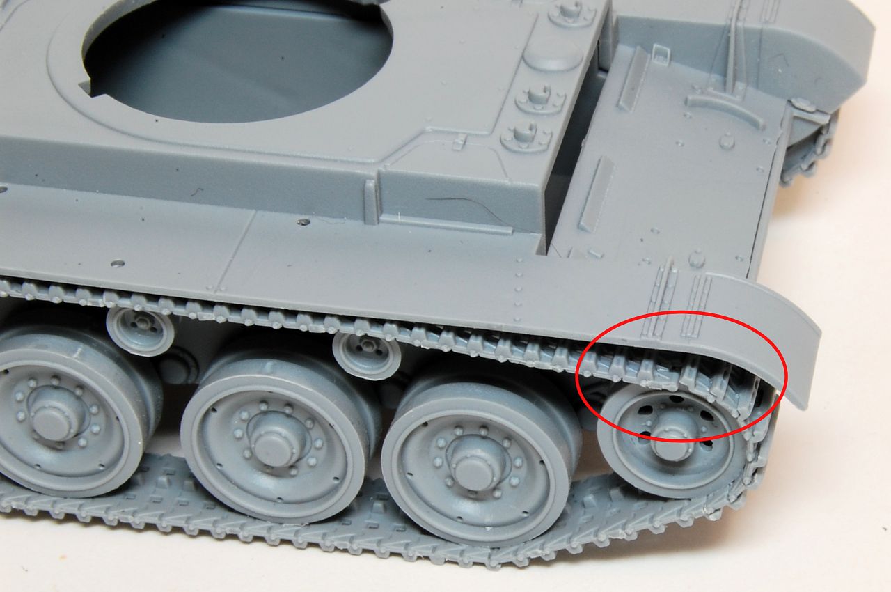
In fact I was able to remove the top run and reposition it without too much difficulty, and the final link then fitted in place exactly, the end of the top run being cemented in place only after the final single link (in this case at the back) :
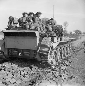
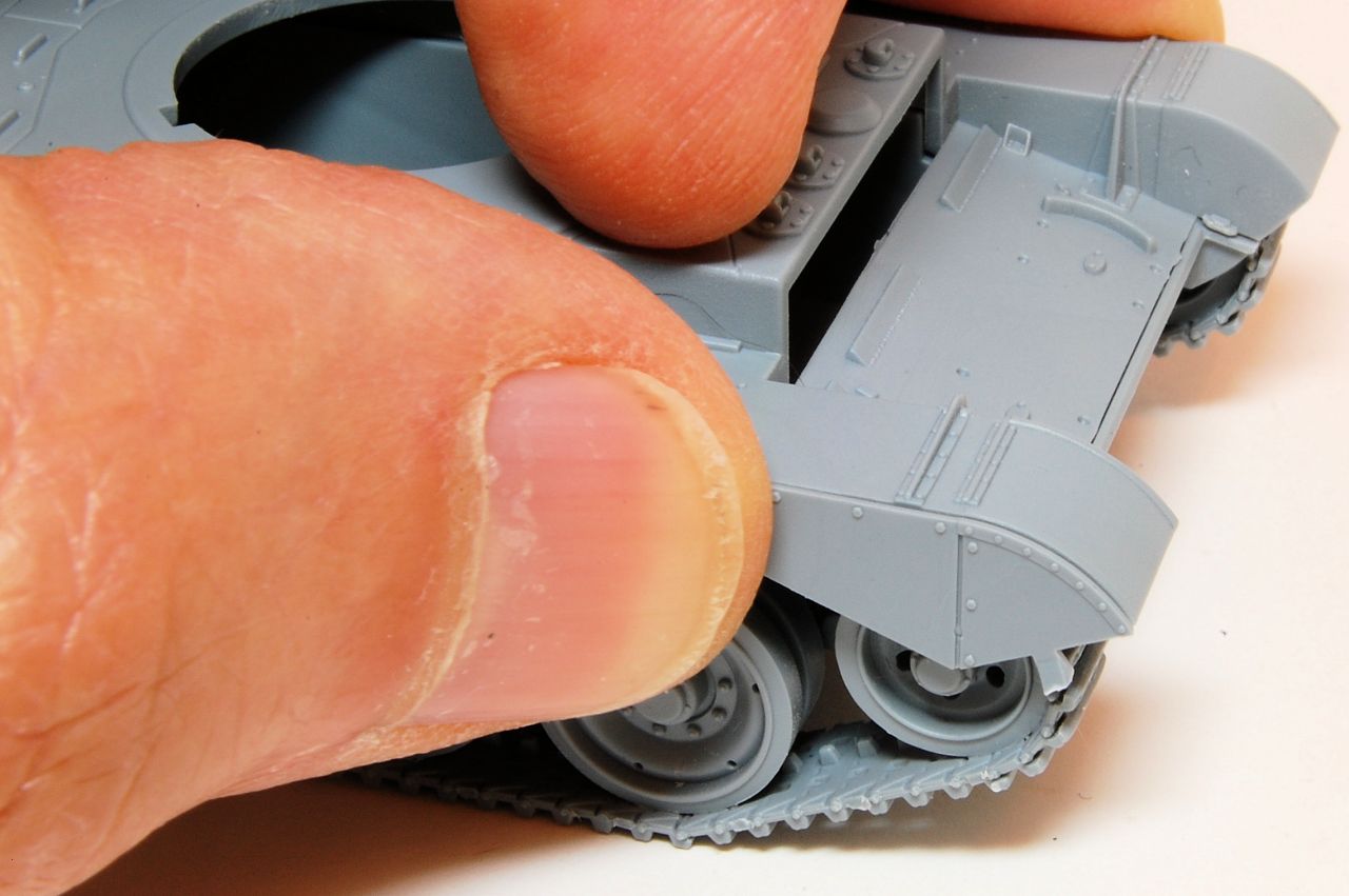
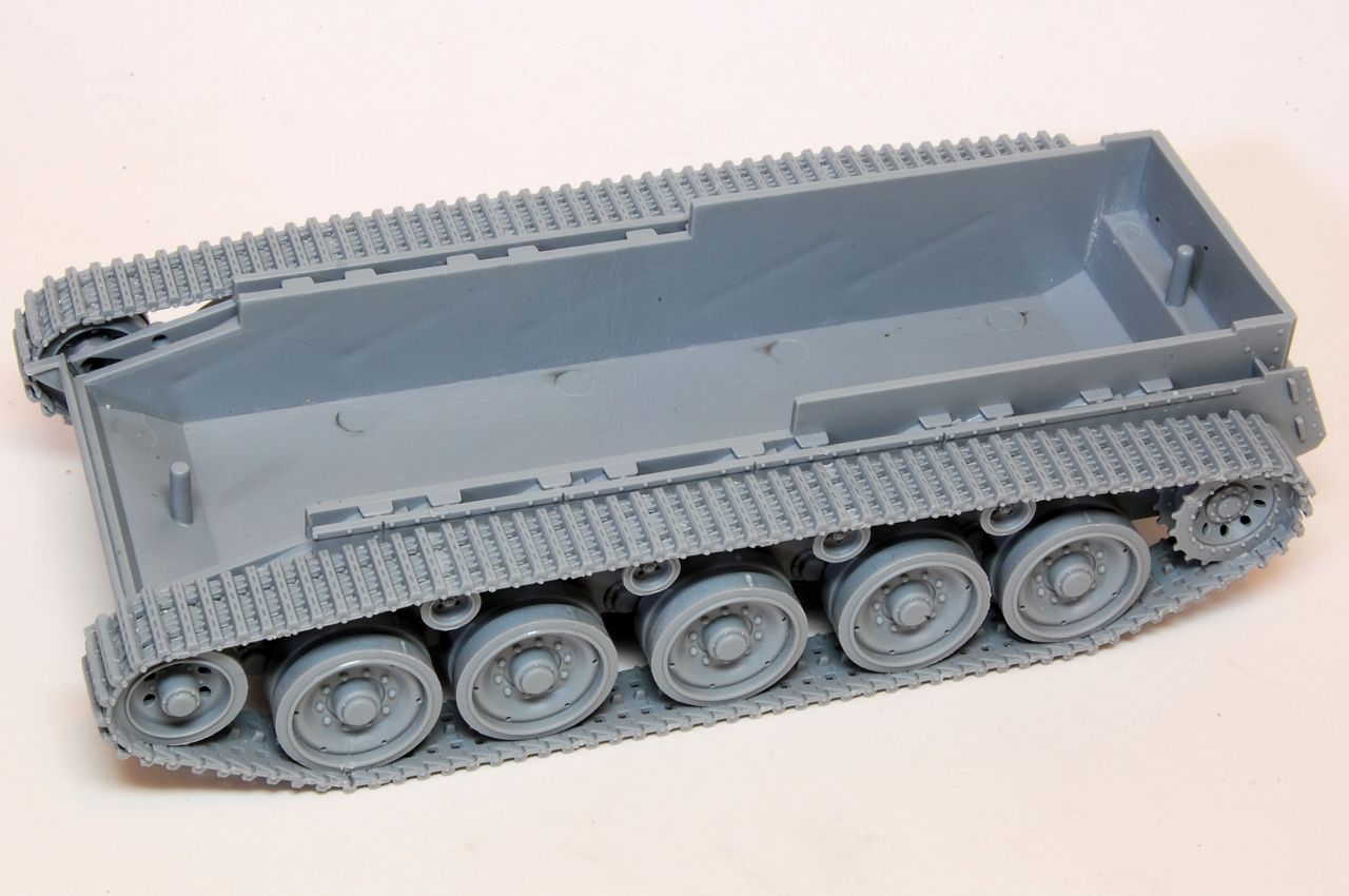
These two photos show that the tracks fit together well, the single links being easy to align with each other, and the amount of track is exactly right. The top length can be fitted in place, and a very minimal sag can be
introduced, as appears to have been the case with tanks in service. Having built a fair number of small scale tanks with link and length tracks over the last few years, I'd say these were the easiest to get right.
Thanks, more later if you're interested.