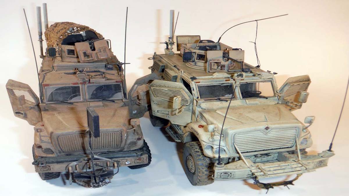
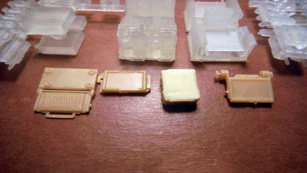
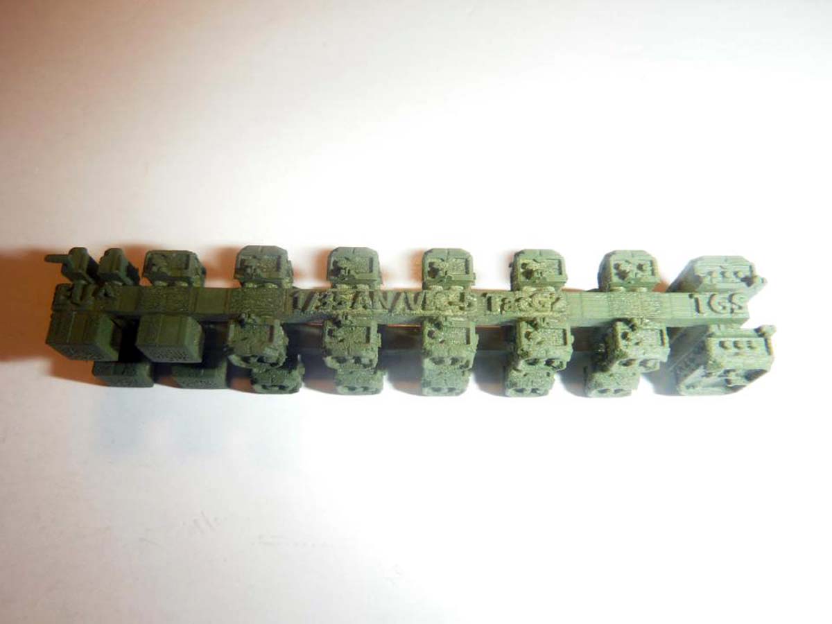
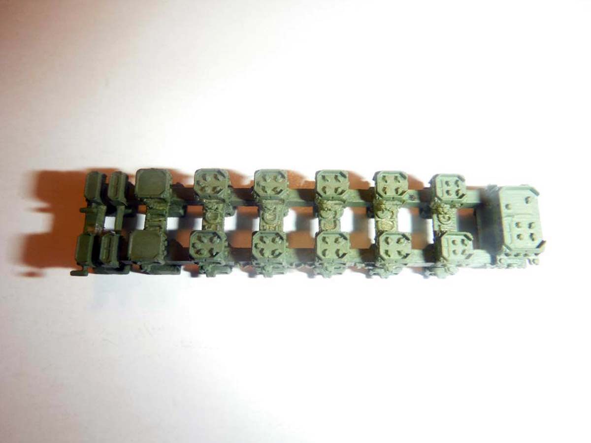
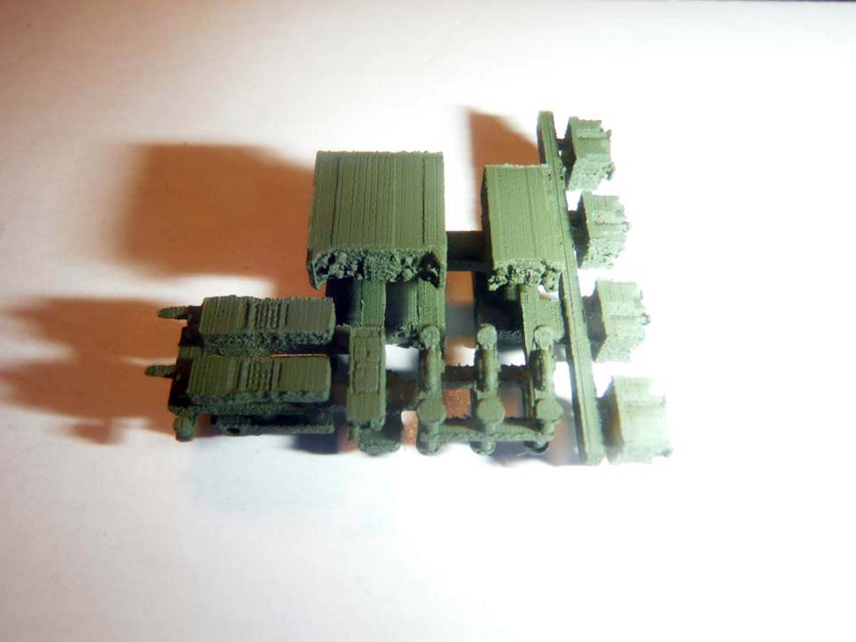
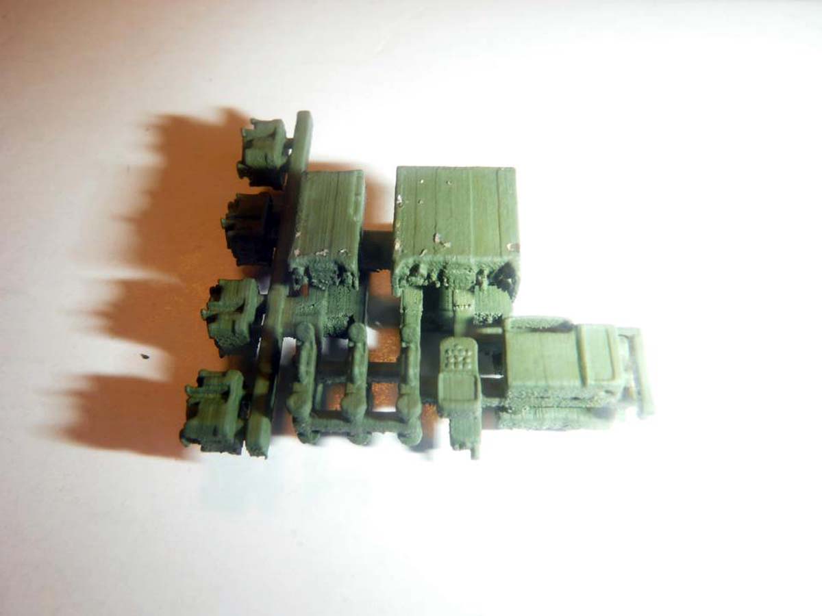
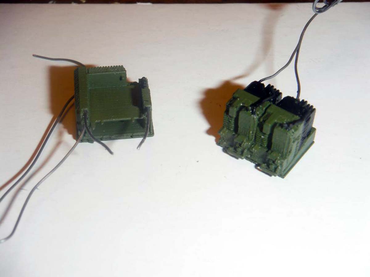
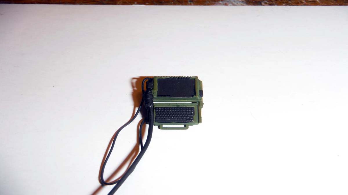
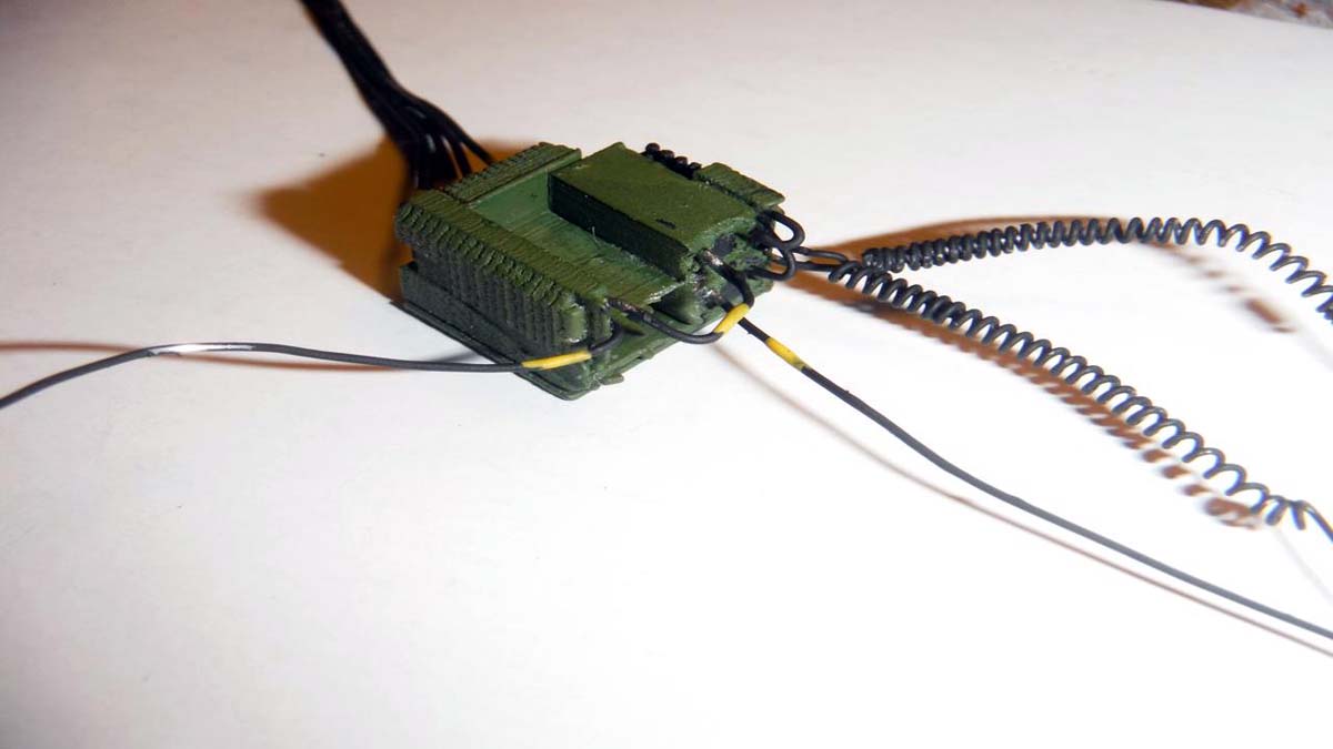
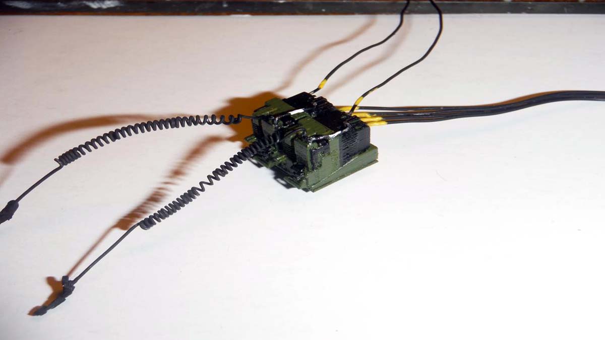
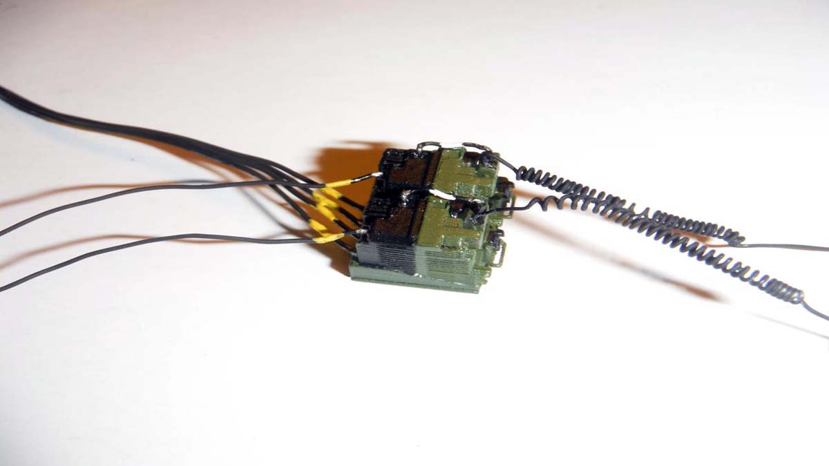
Next feature build/review for Armorama is the recently released Panda Models M1235A1 Maxxpro DASH DXM. Along with the Maxxpro, I got to go inside the interior, the Harris and SINCGAR radio sets and AN/VIC-5 Intercom Set from Mike's MS Productions by Michael Goldberg via Shapeways.
While building and reviewing the kit, I did a side tutorial for the communication equipment and anti-IED system on how to wire them correctly. As with Pandas past MRAP kits, the communications equipment inside was either lacking or completely wrong, hence the tutorial.
The Kit
There is already a video here on Armorama showing the contents of the box, so I won't bore you with all that stuff again and get to the nitty gritty. Just like the other Panda Models MRAP kits, the one is not short of flaws. The major flaw in this kit was the INTERIOR. For those of us who have been on this vehicle or do the research before building know that this is not a Maxxpro DASH DXM due to the interior. The interior is from the first addition of the Maxxpro. Differences between the basic Maxxpro and DASH DXM will be called out in the text.
The Build
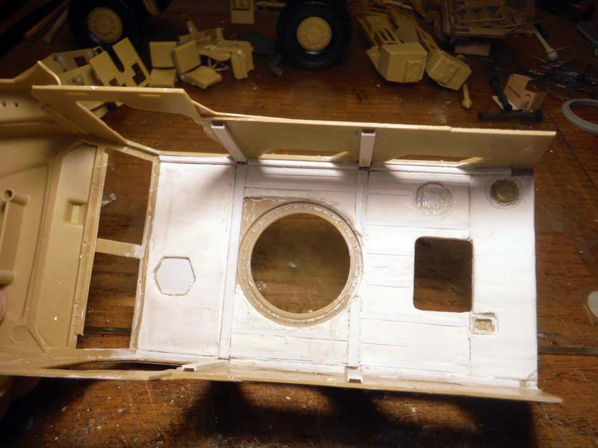
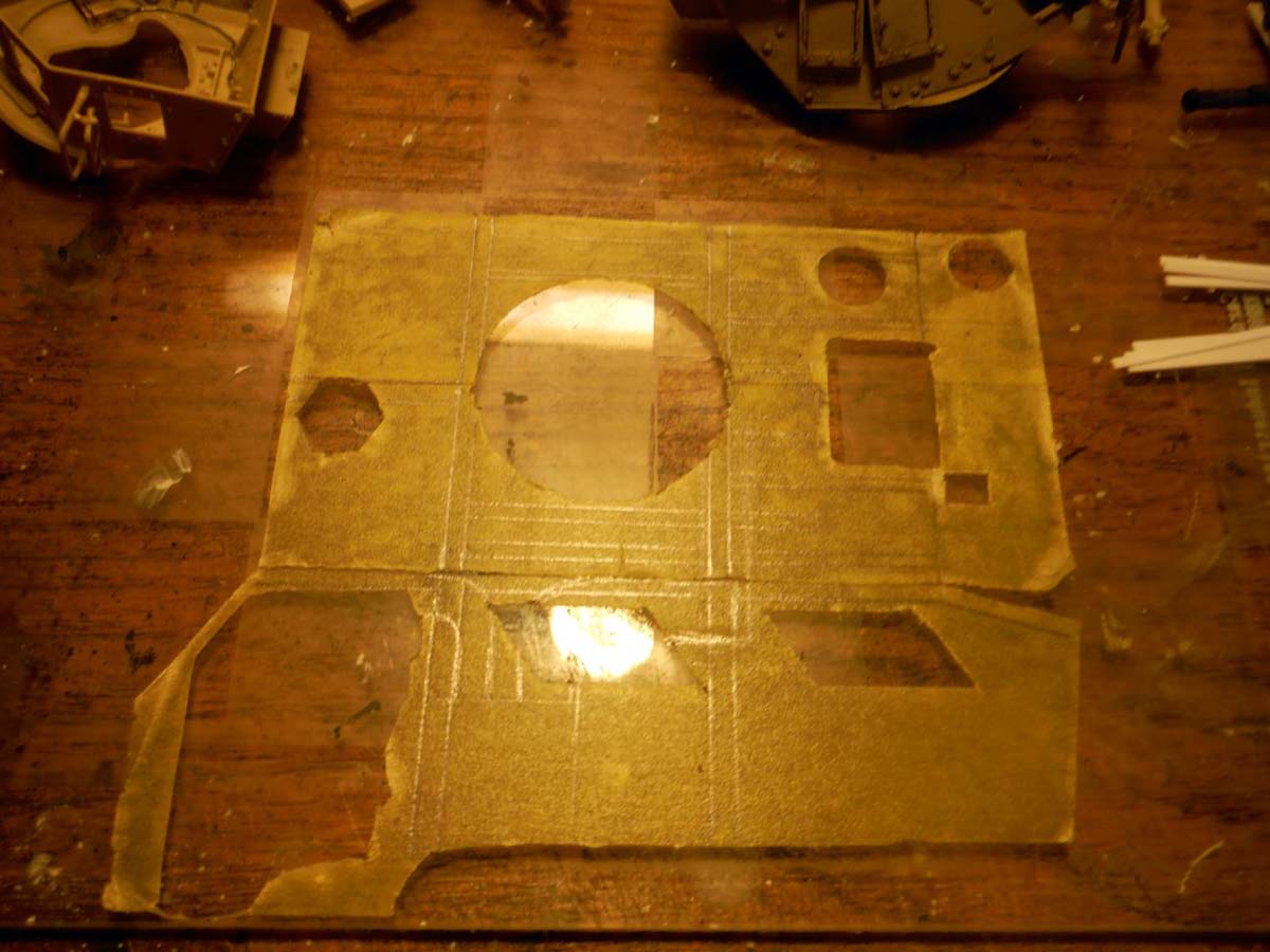
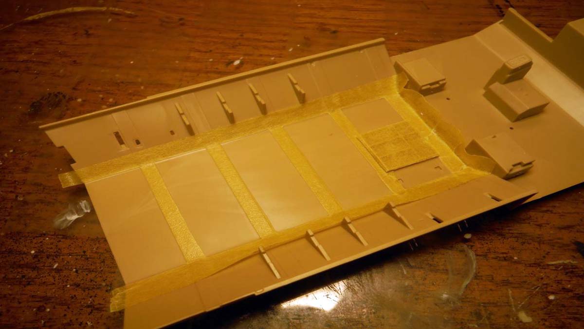
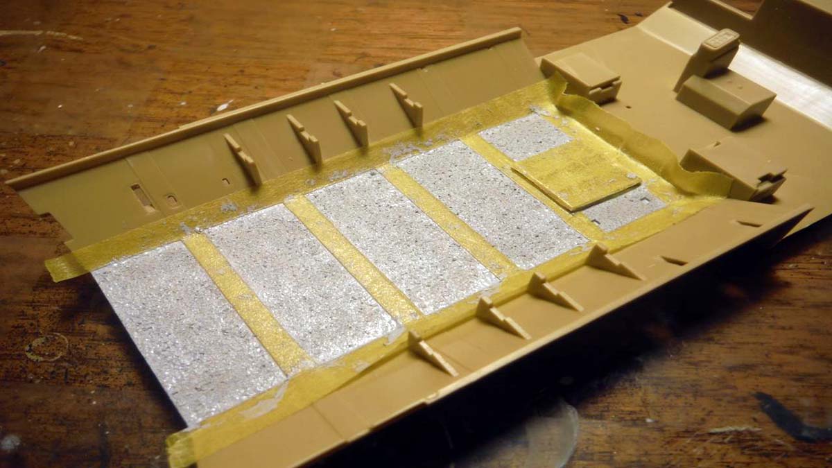
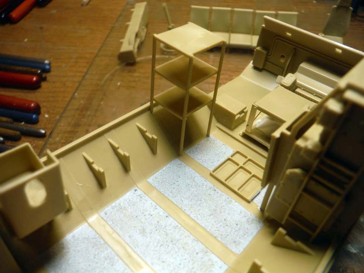
Starting off with STEP 1 by adding the non-slip material to the floor by stippling Mr. Surfacer 500 to it. Tamiya tape was used to mask of the area where the coating is supposed to be.
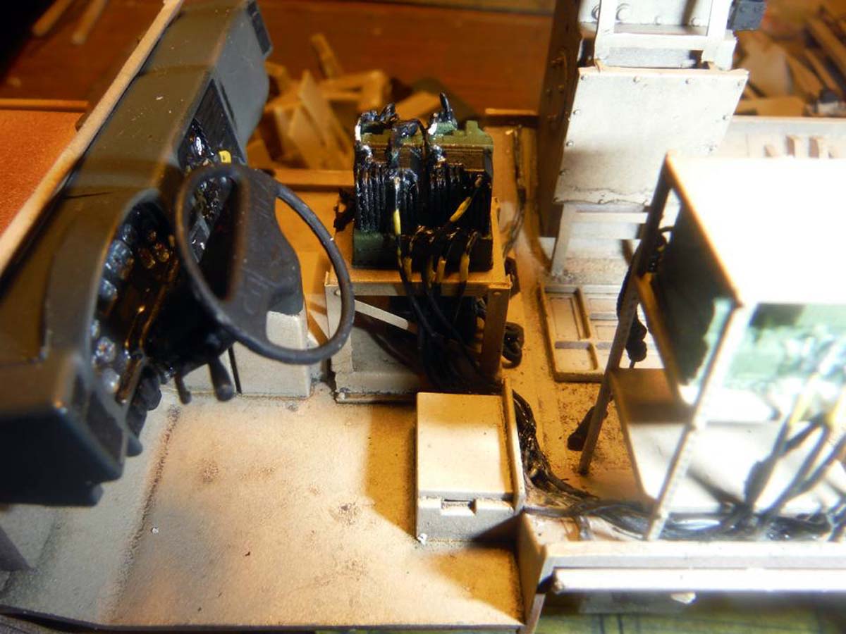
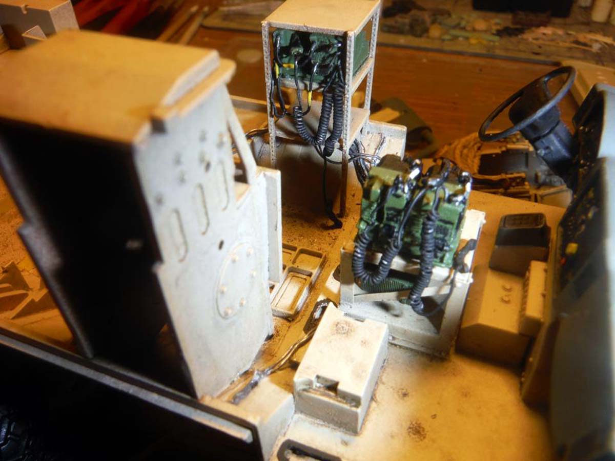
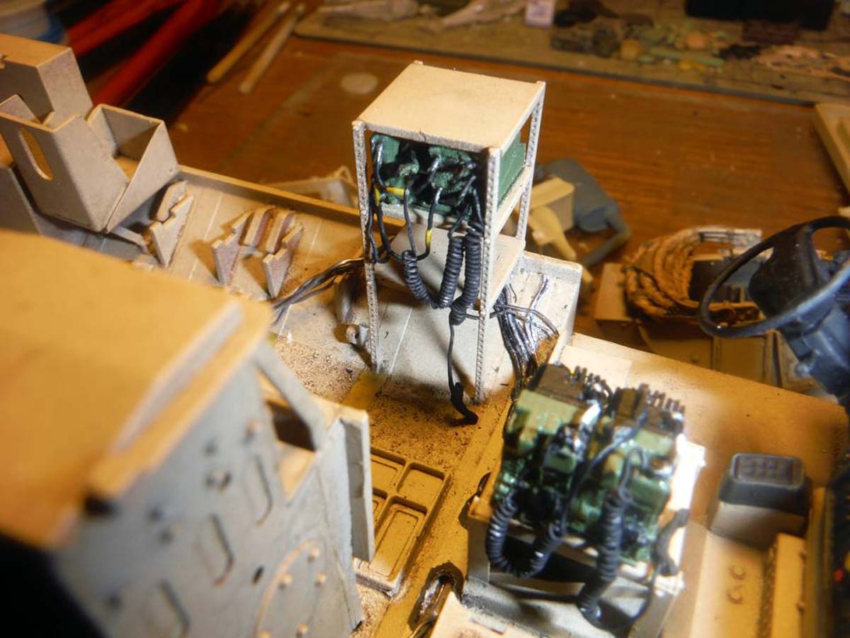
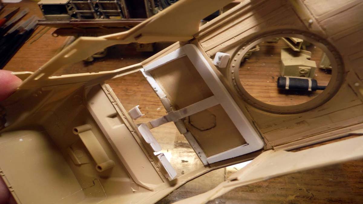
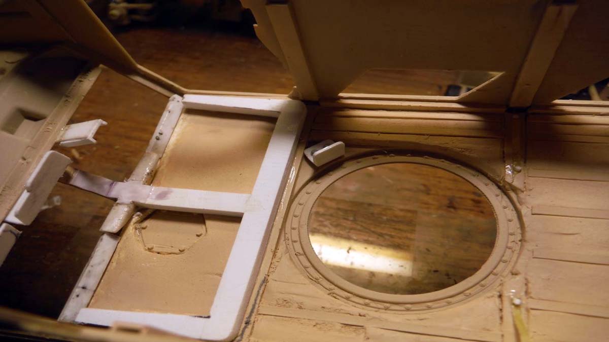
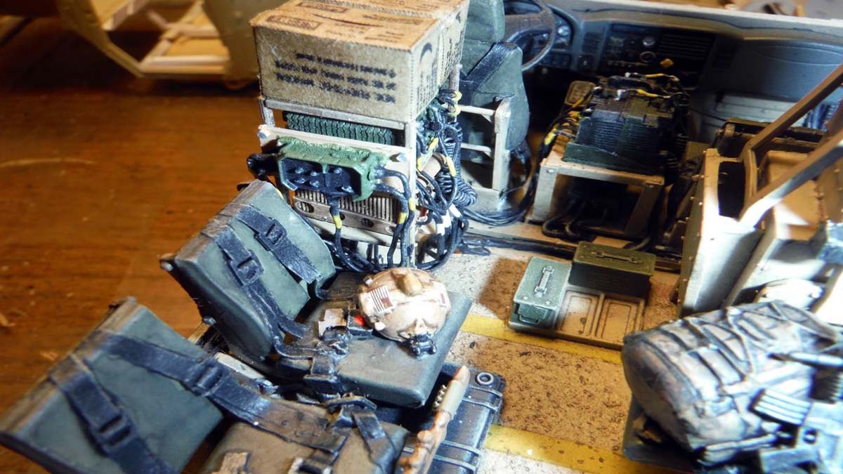
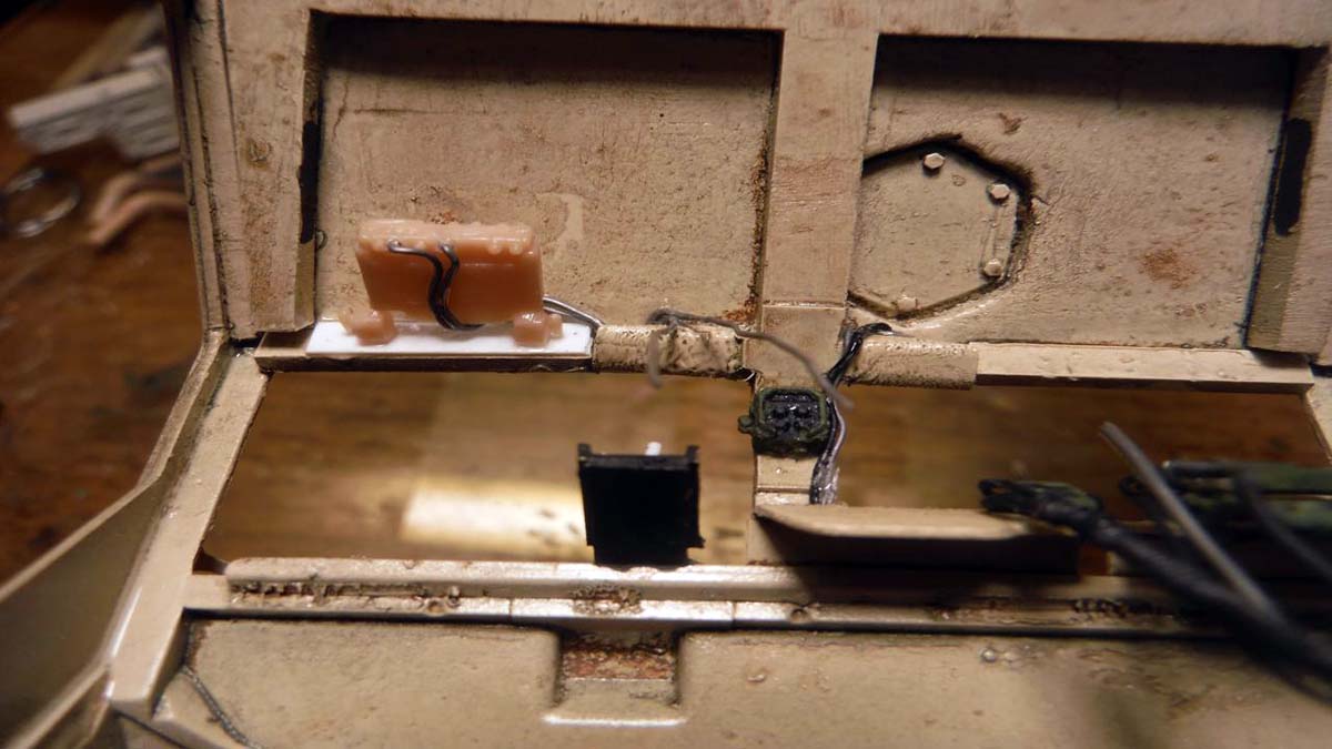
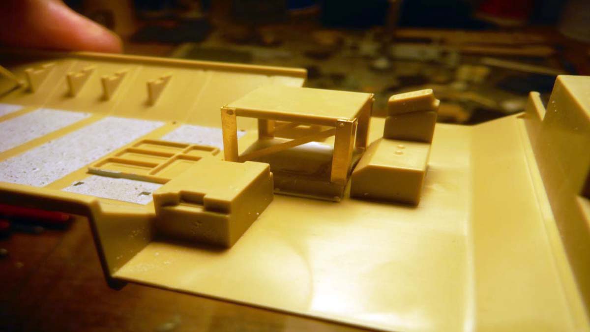
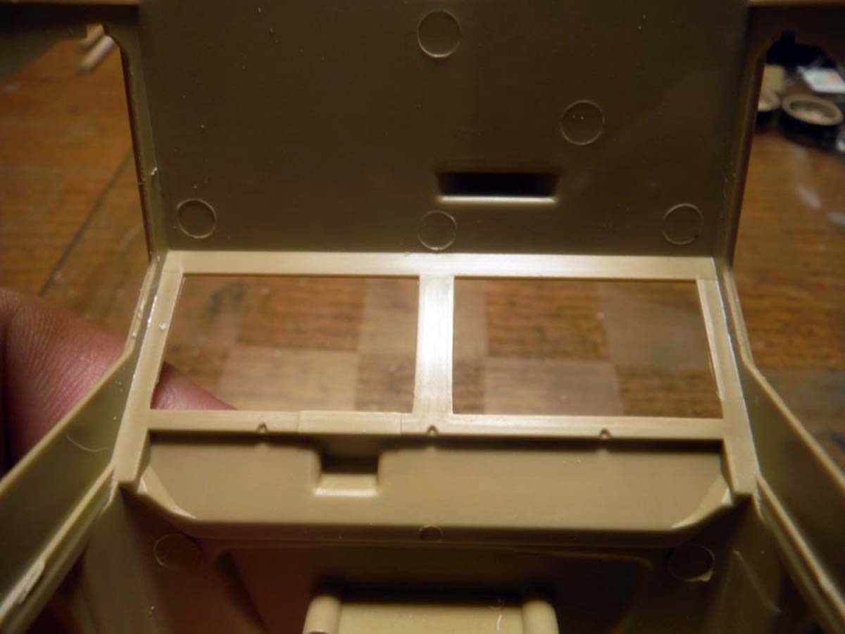
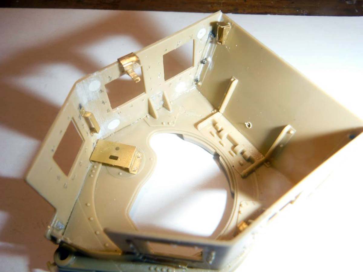
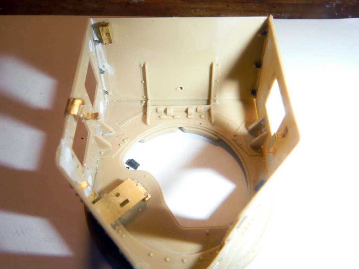
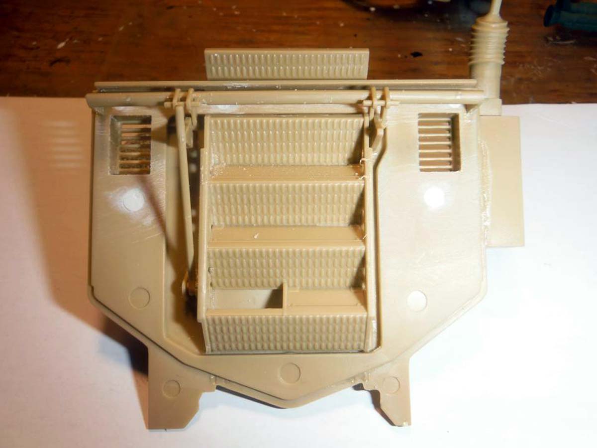
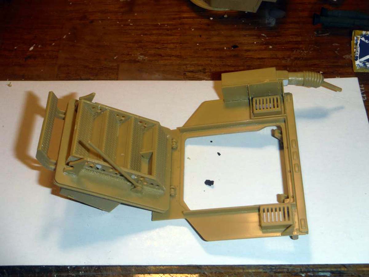
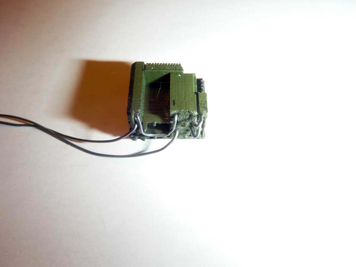
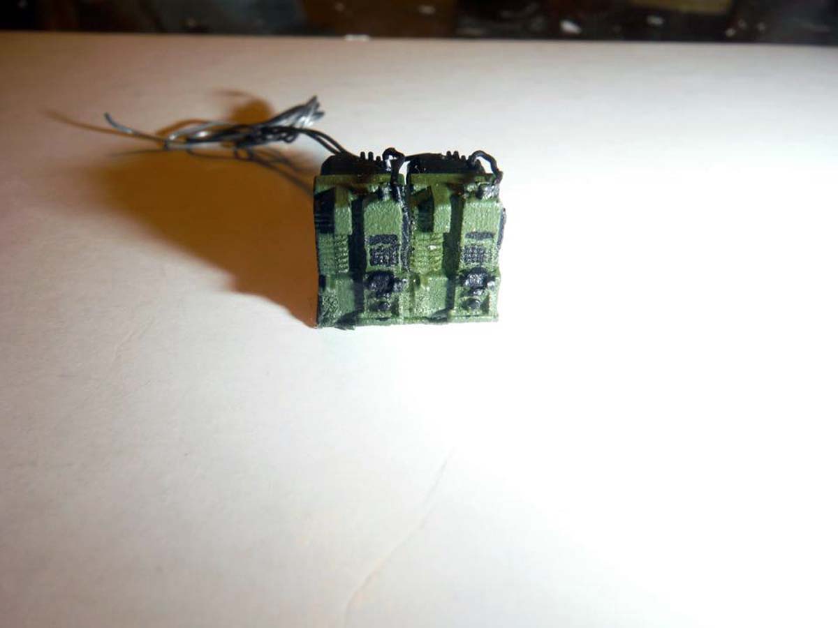
The rack between the drivers and passengers' seat was next. The photoetch bent easy and fit well. The HARRIS radio set will be on top and the FBCB2 CPU will be on the bottom of the rack. Panda Models has something molded to the bottom of the rack but I dont know what it is supposed to be, so I removed it and filled in the hole with thin plastic sheet and Squadron White putty.
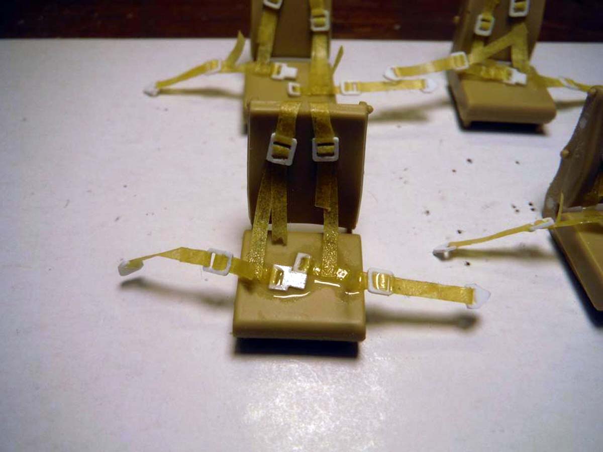
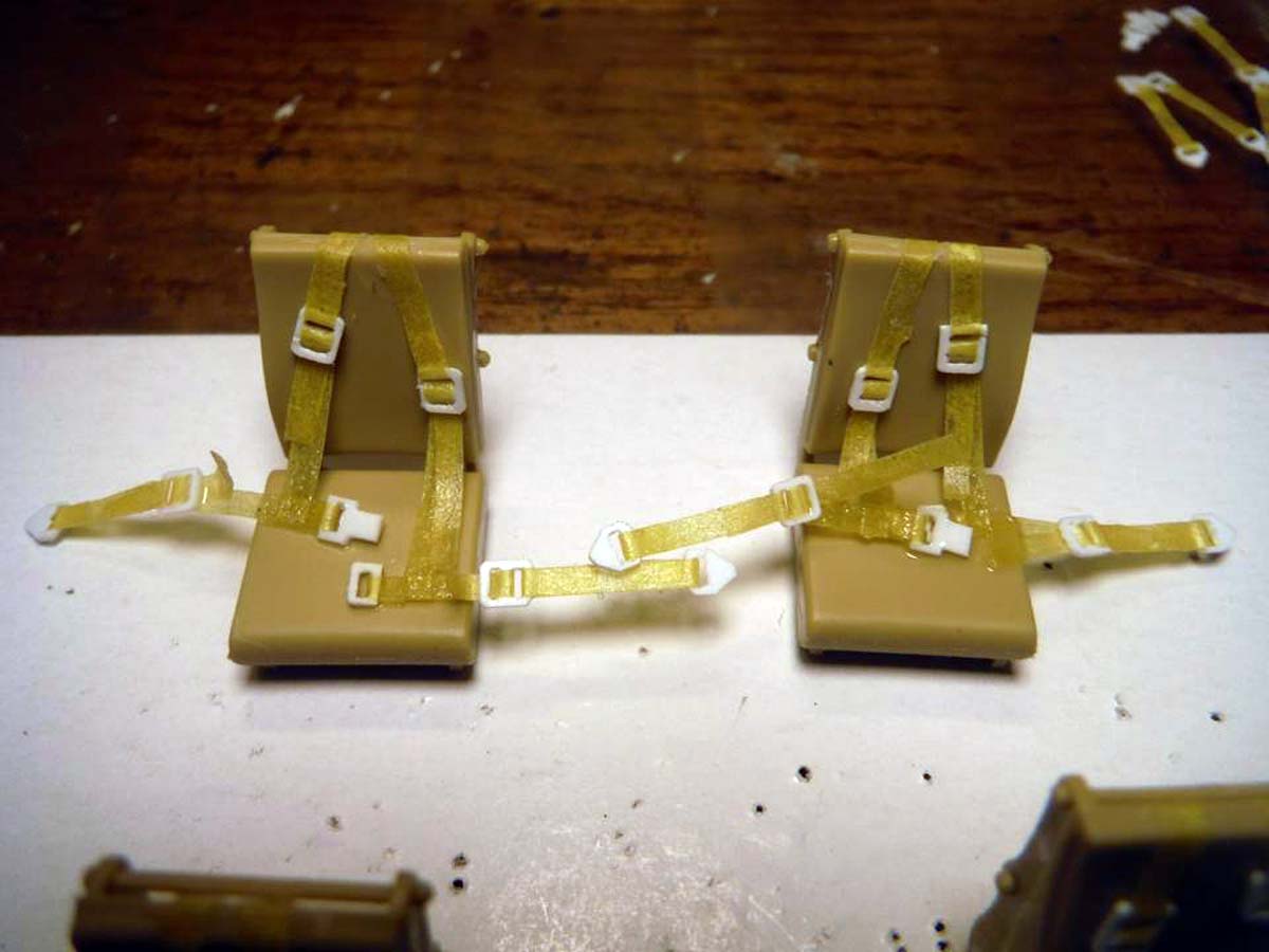
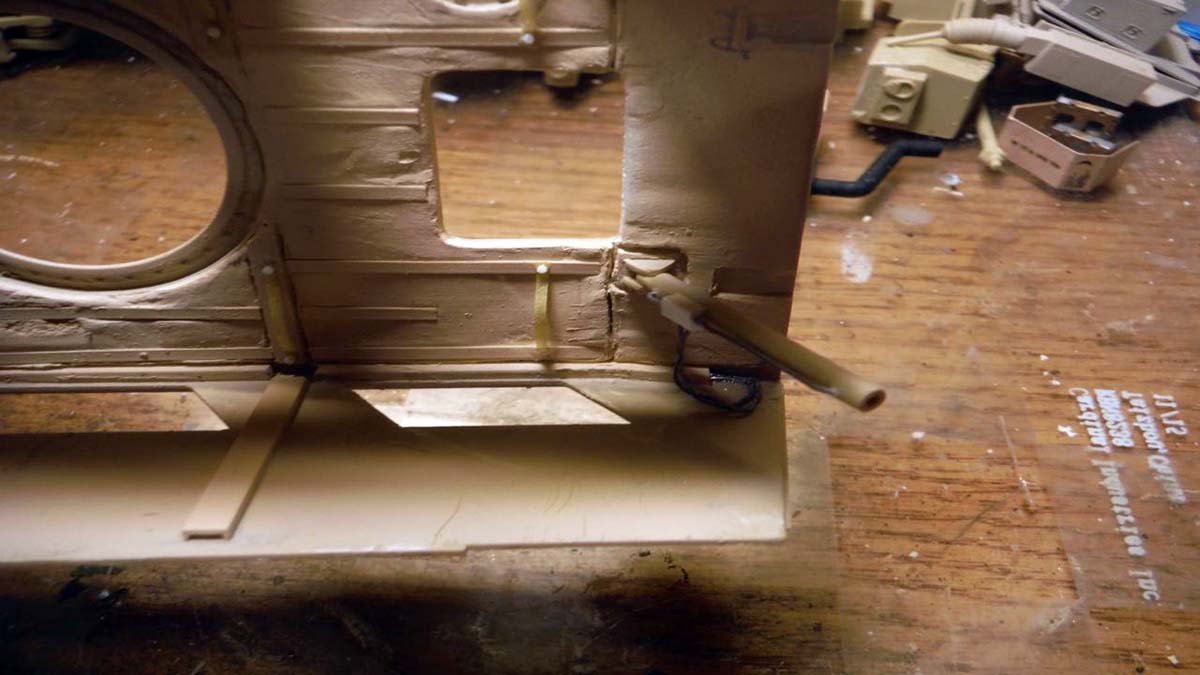
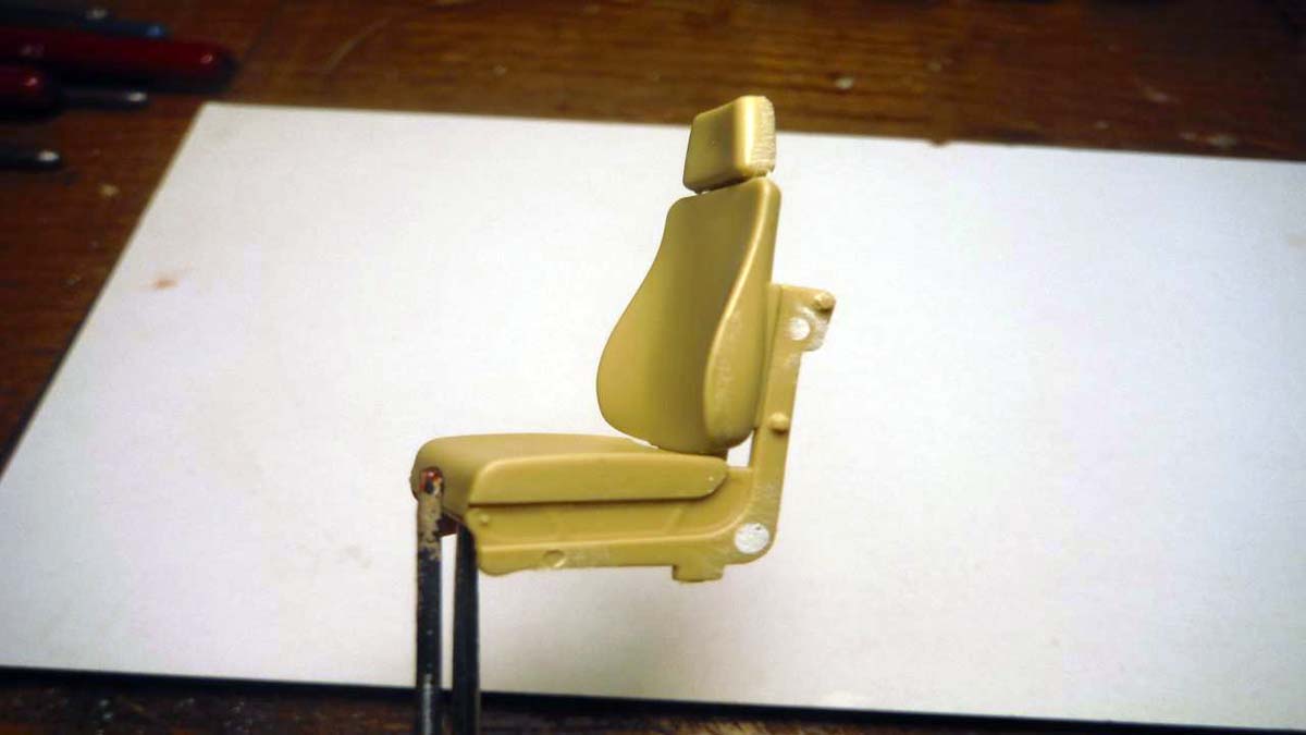
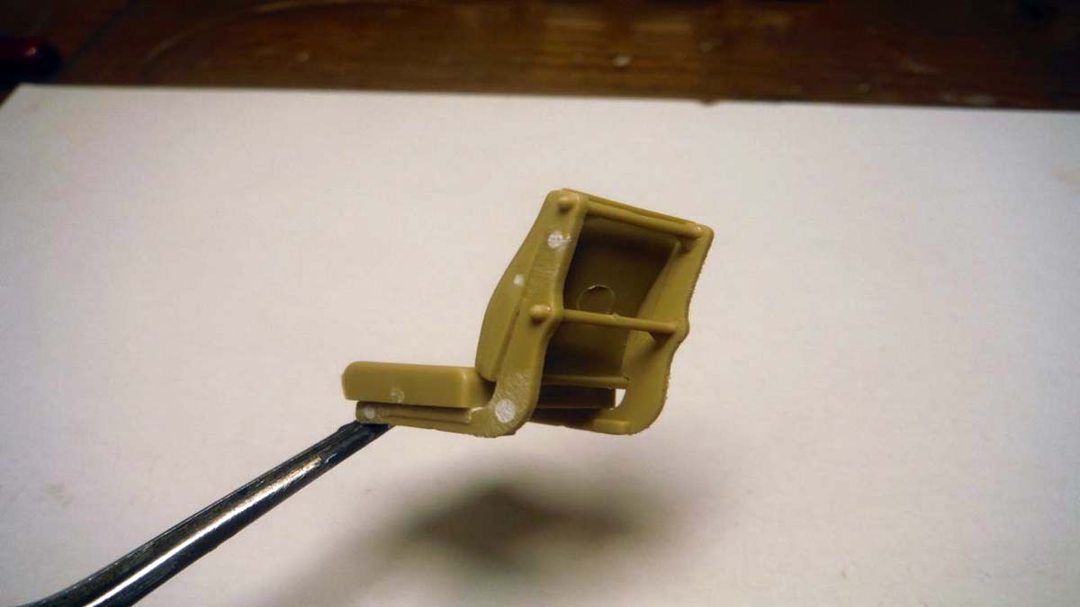
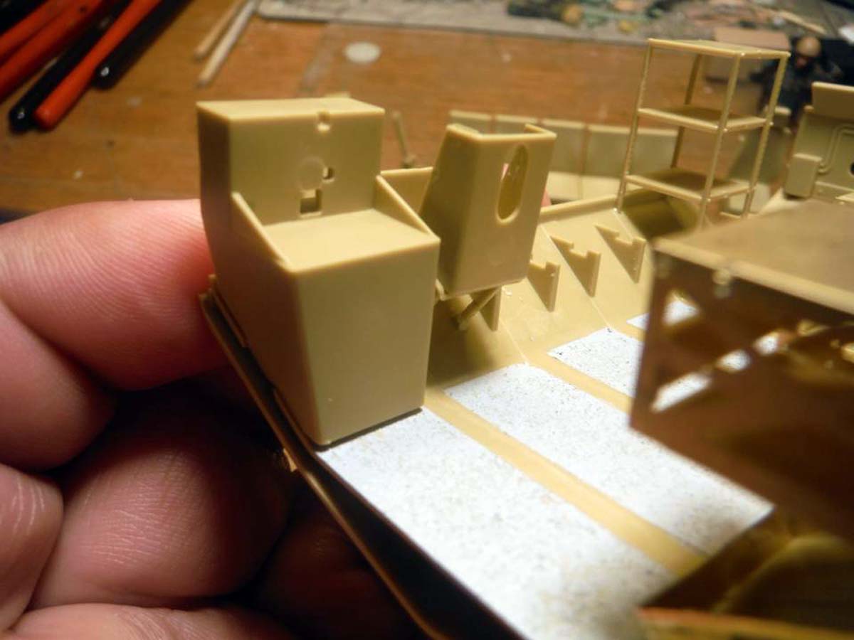
On the real vehicle, there is a cable conduit between the drivers and passengers' seat and runs along the right of the passenger seat. There is nothing on here between the seats on the Panda kit. I will add what I can before we add the seats using plastic stock. The lack of the proper space behind the seats will be the issue in adding the whole conduit. The seats where next, but there is one minor and two major issues with them. As far as the seats themselves are concerned, they are nice. The minor issue is that they lack seats belts. I was thinking about using the seat belts from Eduard MRAP set, but those are 3-point harnesses. I used Tamiya tape for belts and plastic stock for the buckles. The two major issues with the seats are that the lack the rope and mesh ratchet system that holds the seats up and the attachment points for the seat belts and seats on the floor.
****NOTE: In my kit, Parts F56x2 where both short-shot, but it really didn't hinder the build.****
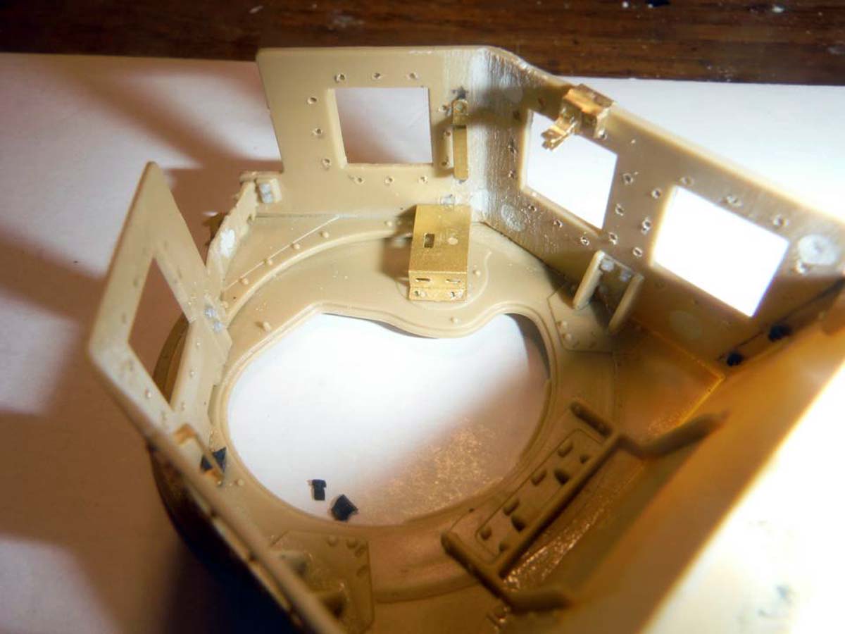
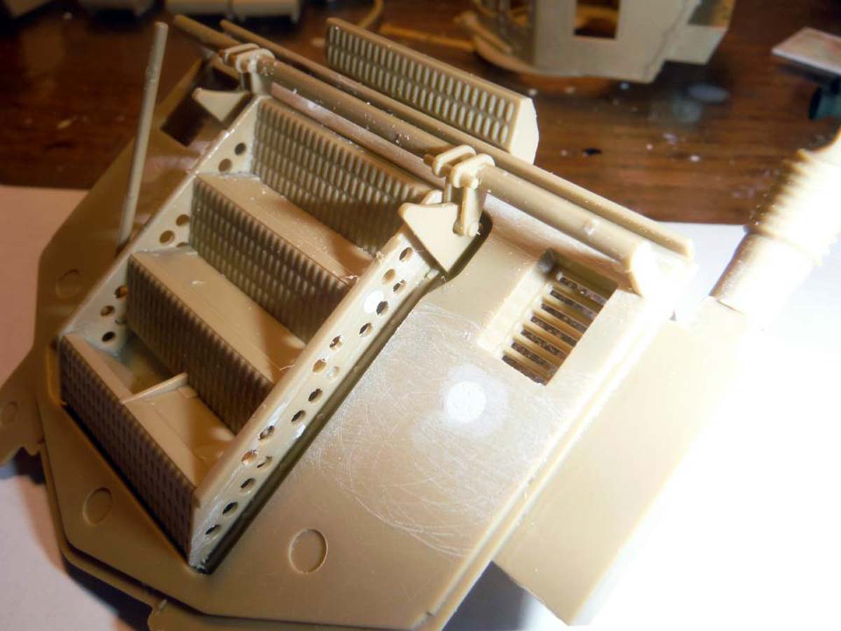
There was no issues as far as fit with step 2. The major issue I found here was with the photo etch. A couple of the parts where not etched all the way through in the lower right-hand corner, to include Part PE4. I'm not sure if this is just the set in this kit or in all the first run kits. Careful scoring along the lines of the part helped remove it, just don't use a new blade because it will dull it quick. Also, Part PE4 did not have any bend lines, so measure the part or use eyeball accuracy to bend it. Plus, glue it to the angled side wall first, then attach the completed rack and glue PE4 to that. Later I found out that this was an issue with a few kits only.
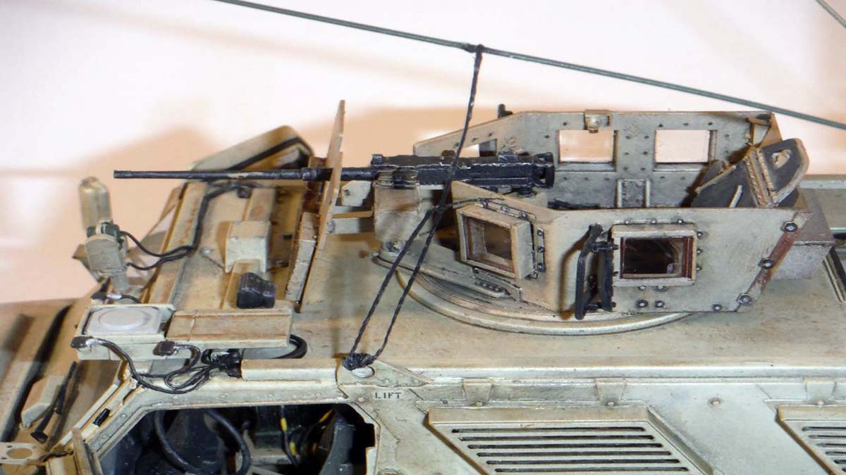
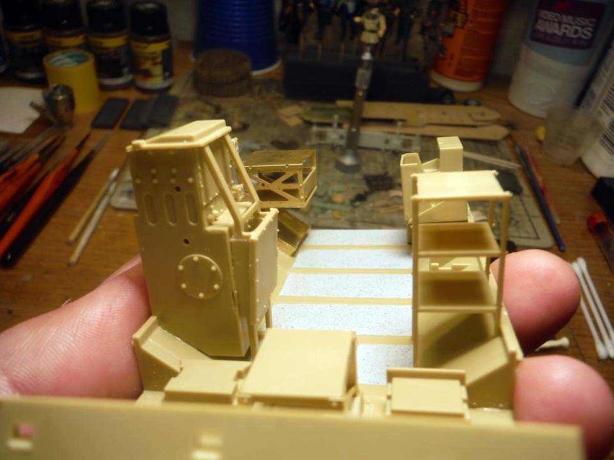
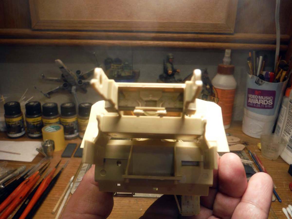
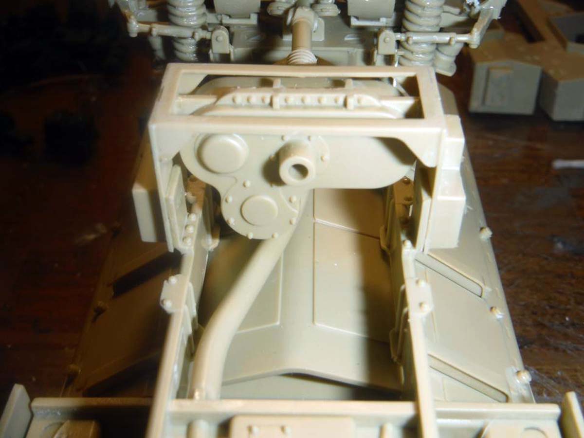
The radio rack and "AC" unit went together well with-out any filling needed. One problem here though, there is no option to have the gunners platform in the up position, so you can't add a gunner figure to the model. With careful cutting and lots of patience, it can be done.
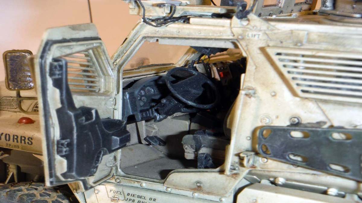
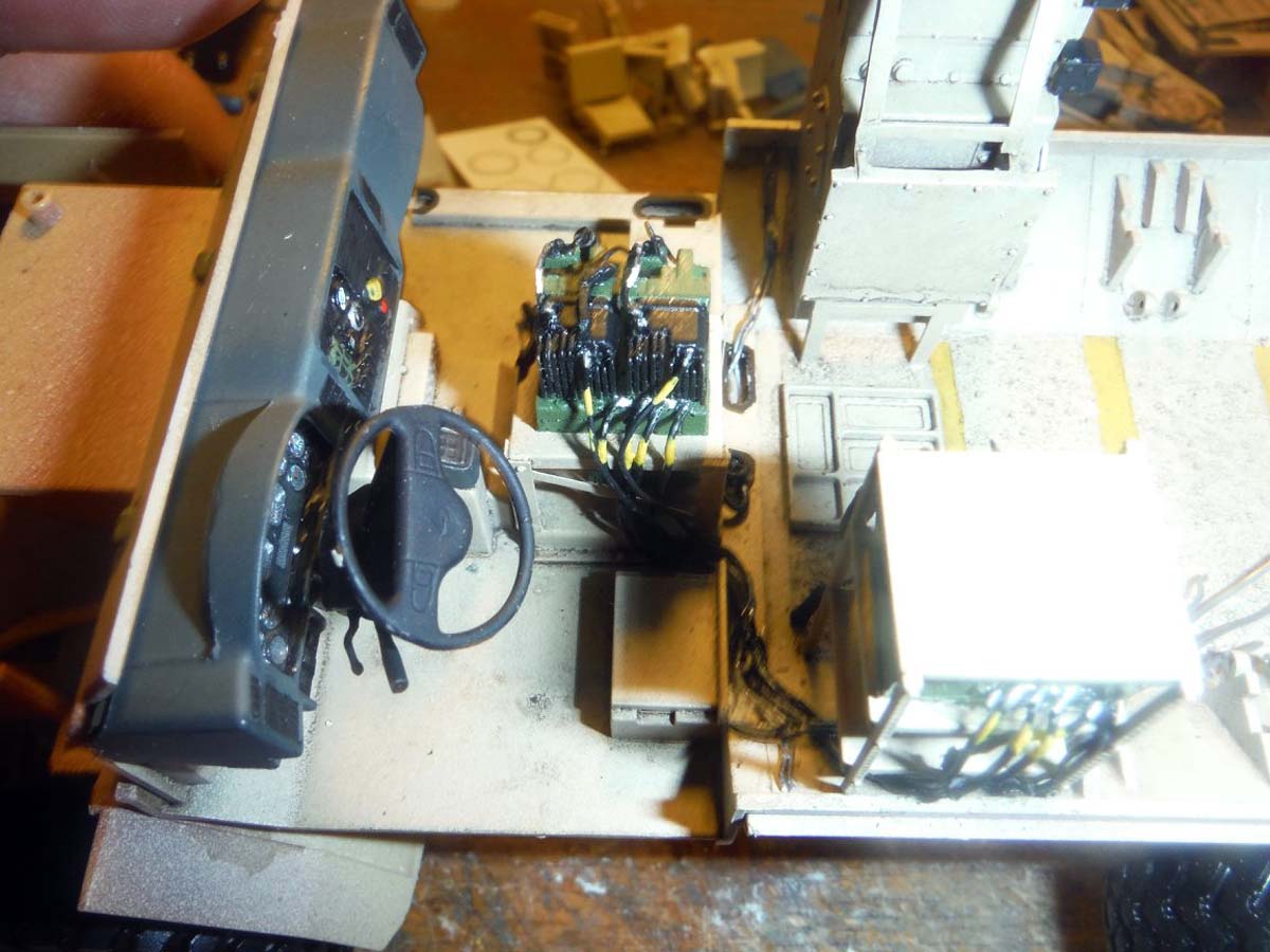
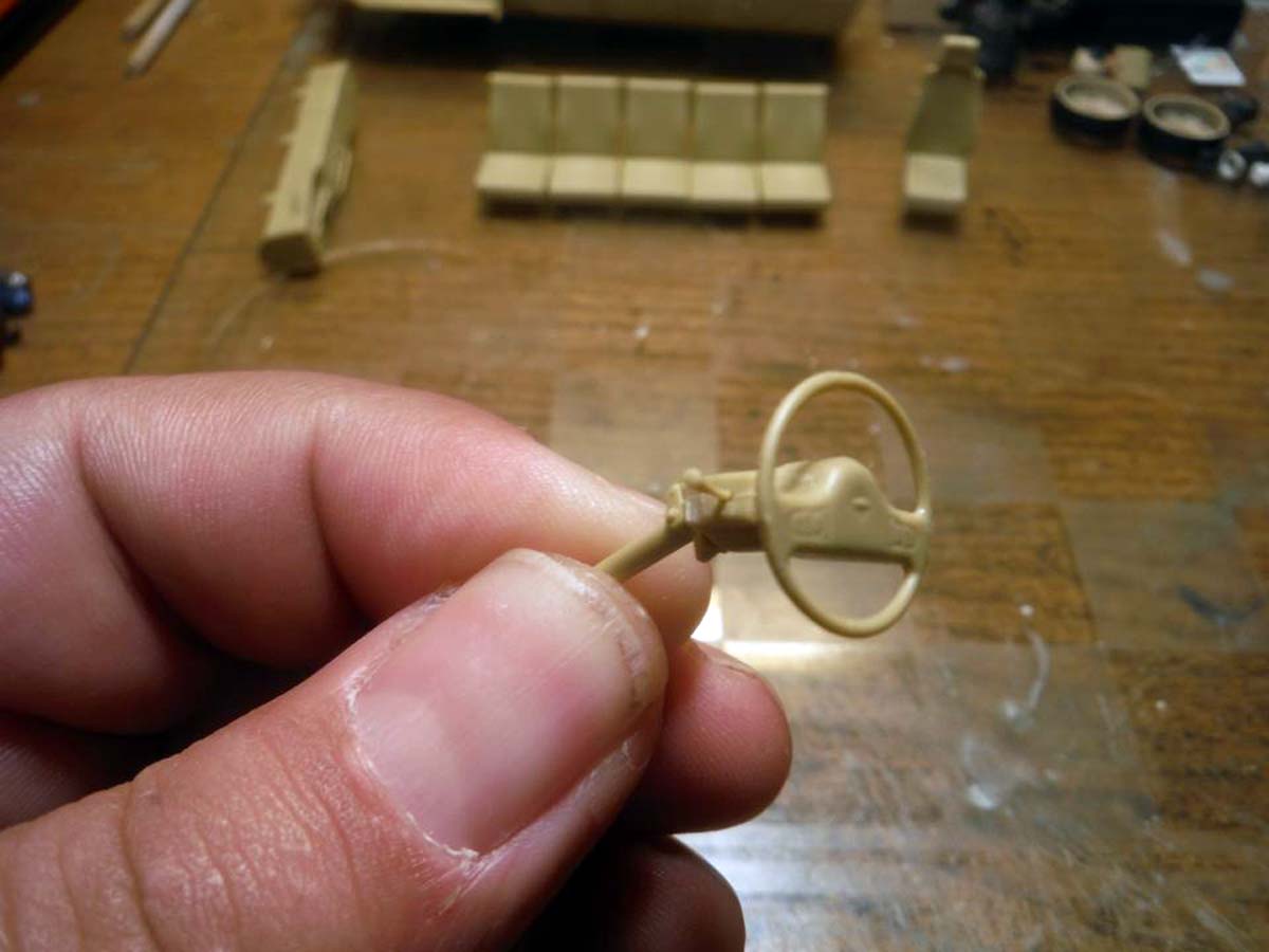
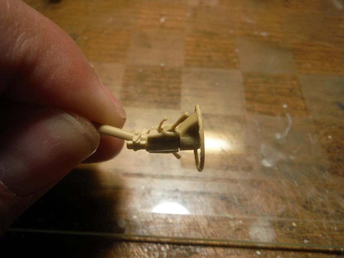
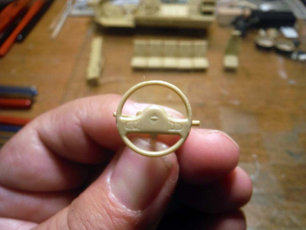
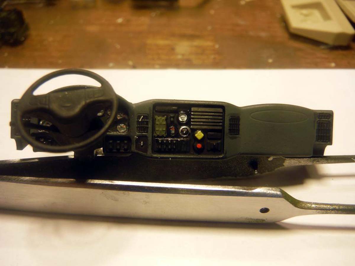
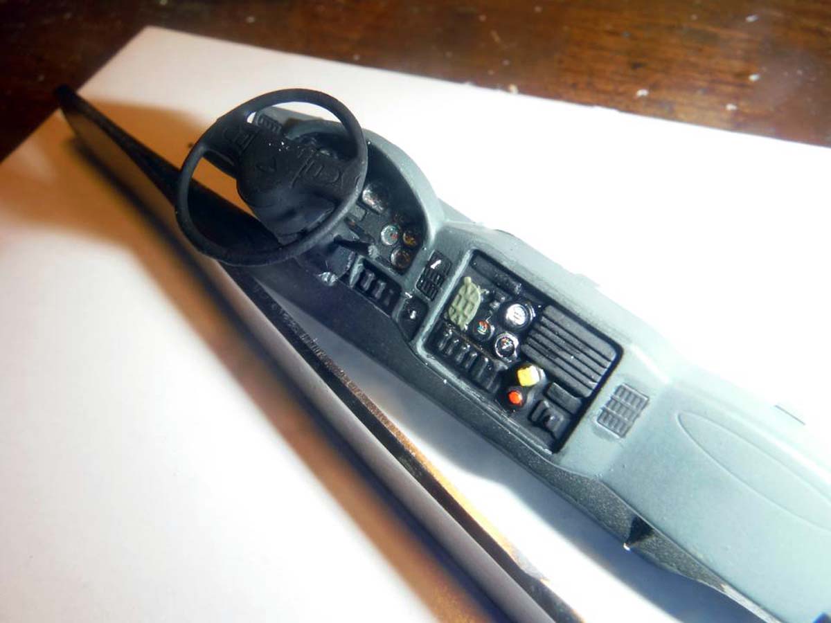
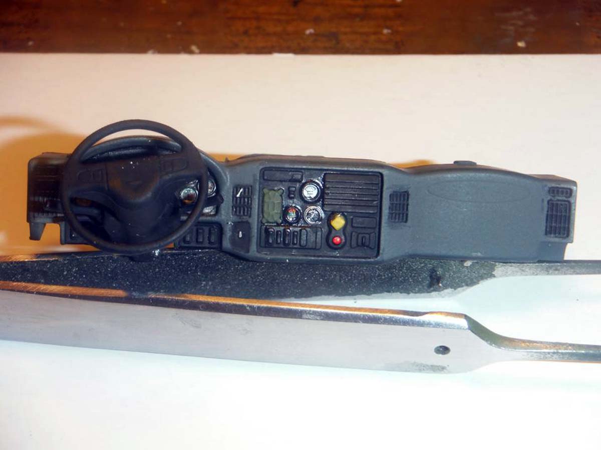
The dash board is really nice and detailed. I was going to add some lines and cables under the dash to the steering wheel column, but decided not to because I was running behind on the build. At this time, I do have the lower interior ready for cables and radios. The dash and seats are left off for ease of painting and to add missing stuff like seat belts.
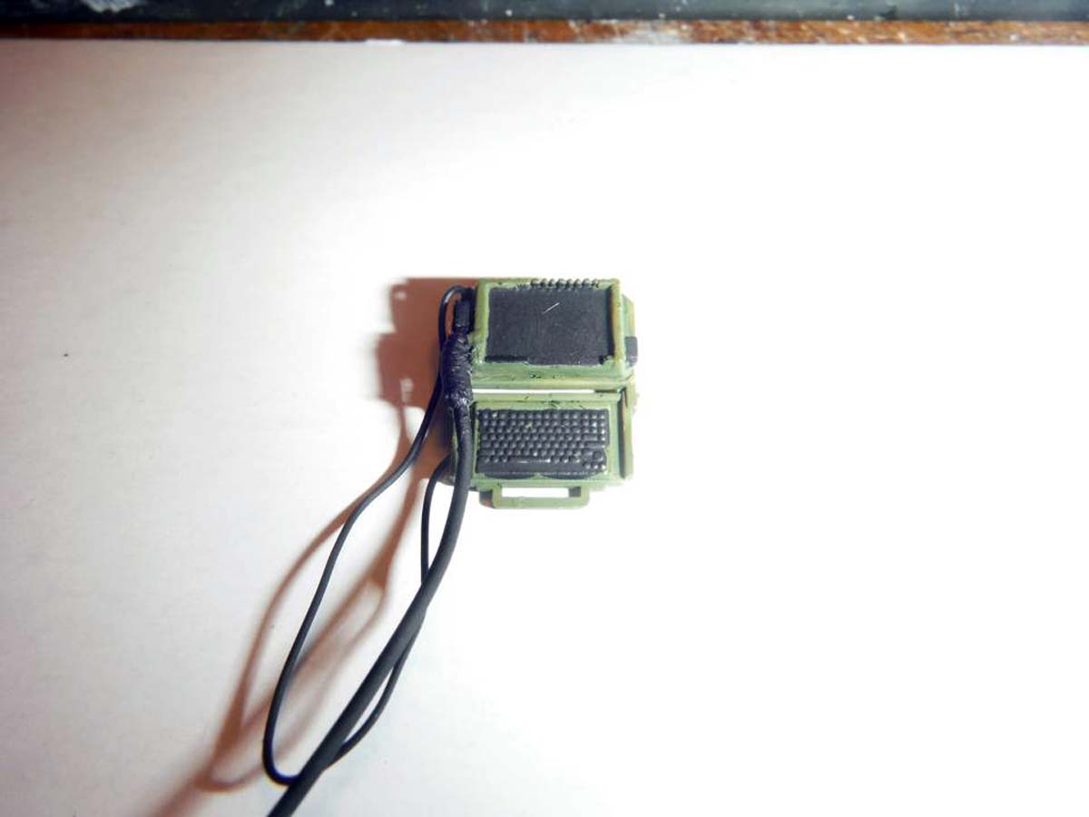
***Note: The PLGR. FBCB2 monitor and keyboard, and Fire Suppression system switches do not mount to the dash board, but instead to a bar that is welded right under the window frames. This will be added once I start on the inside upper hull.***
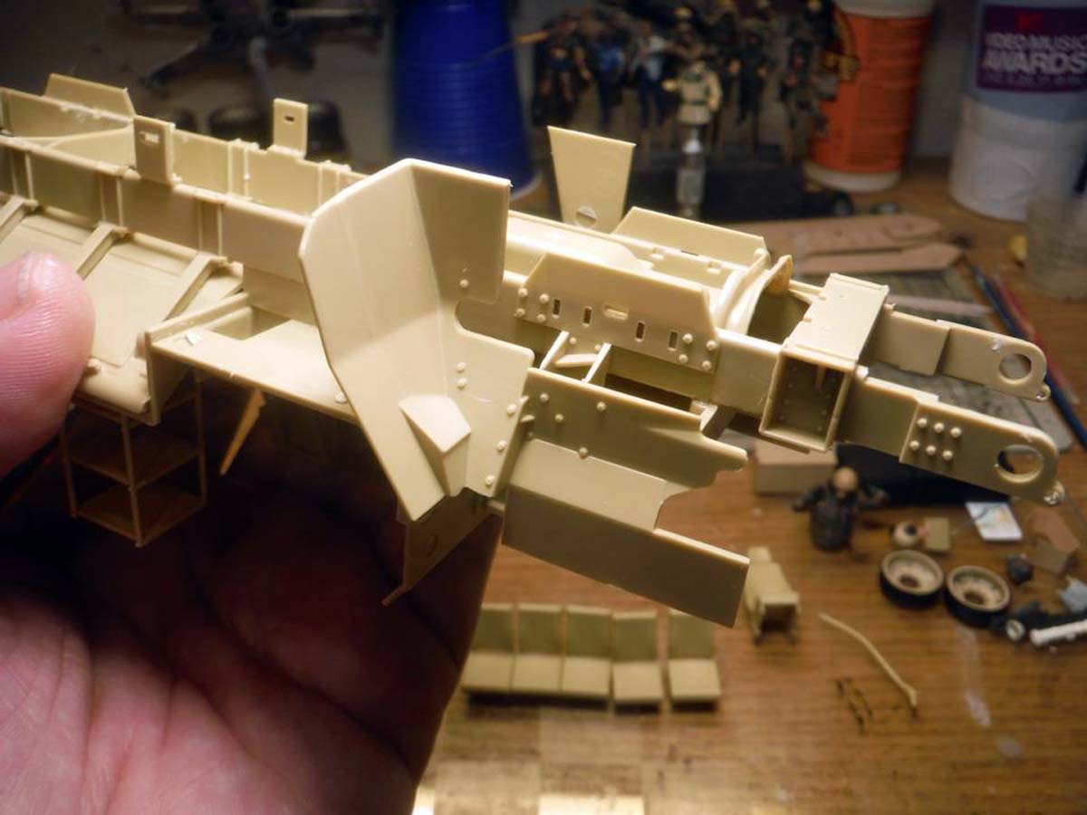
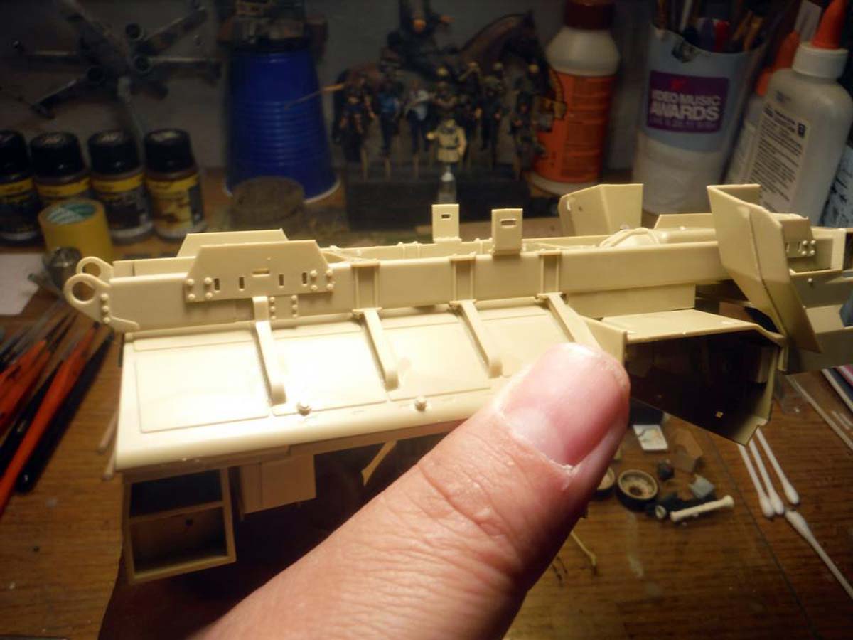
STEP 3 has you attaching the frame, lower body and upper body together. This is going to have to wait. The interior ceiling has several punch marks to deal with, 3 holes to fill, and is missing a lot of details. This will be done after I am finished with the lower interior. Since there needs to be a lot of work done to the inside of the upper hull, I decided to jump ahead to STEP 4, 5, and 6. In Step 3, all I did was attach the fender flares and part B43 to the frame. Then I went ahead attach the frame to the bottom of the lower hull.
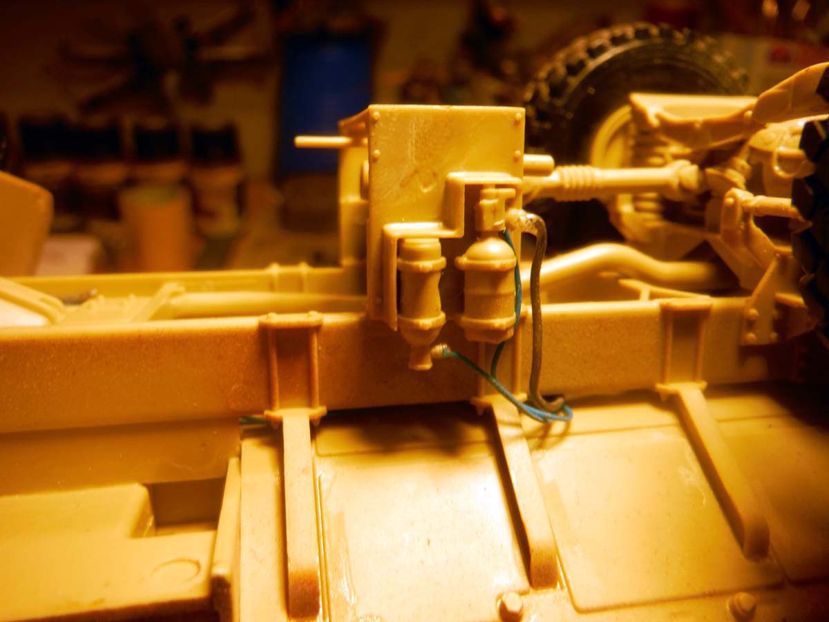
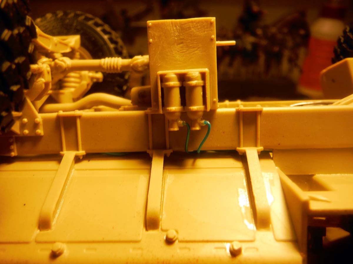
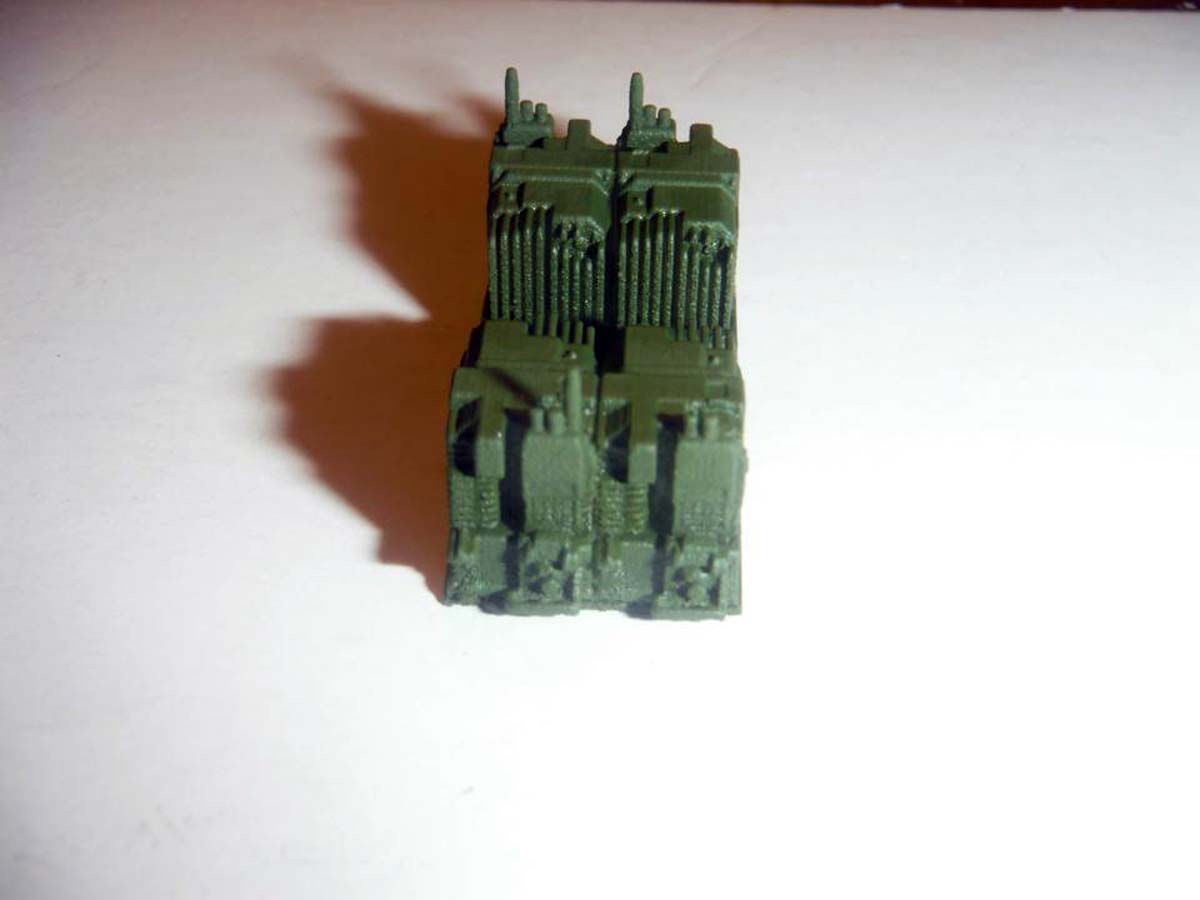
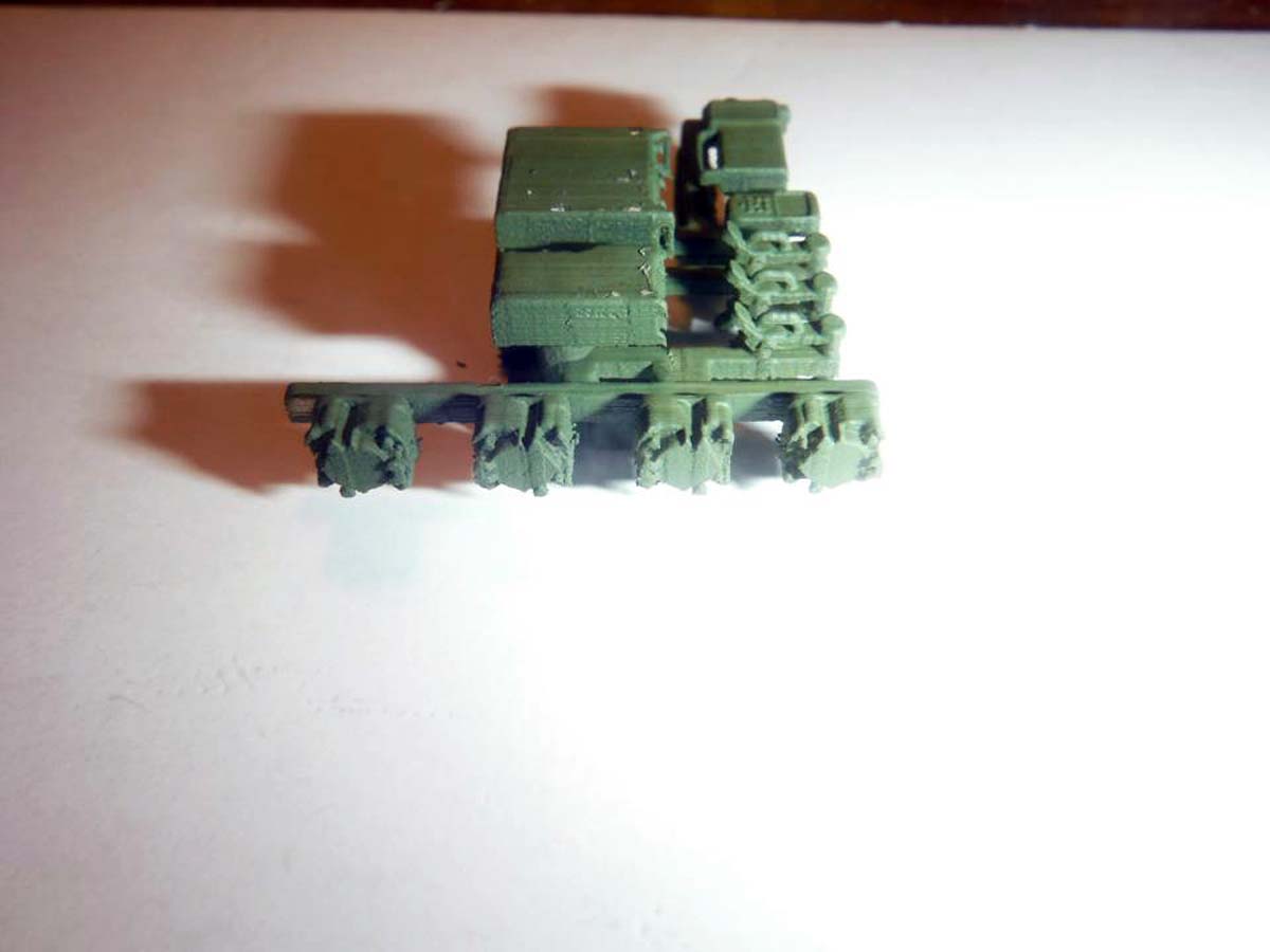
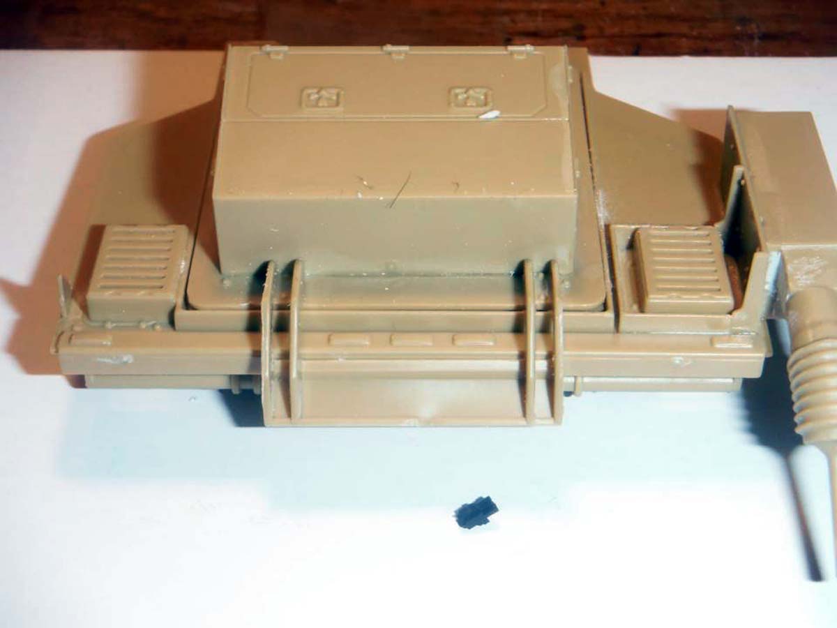
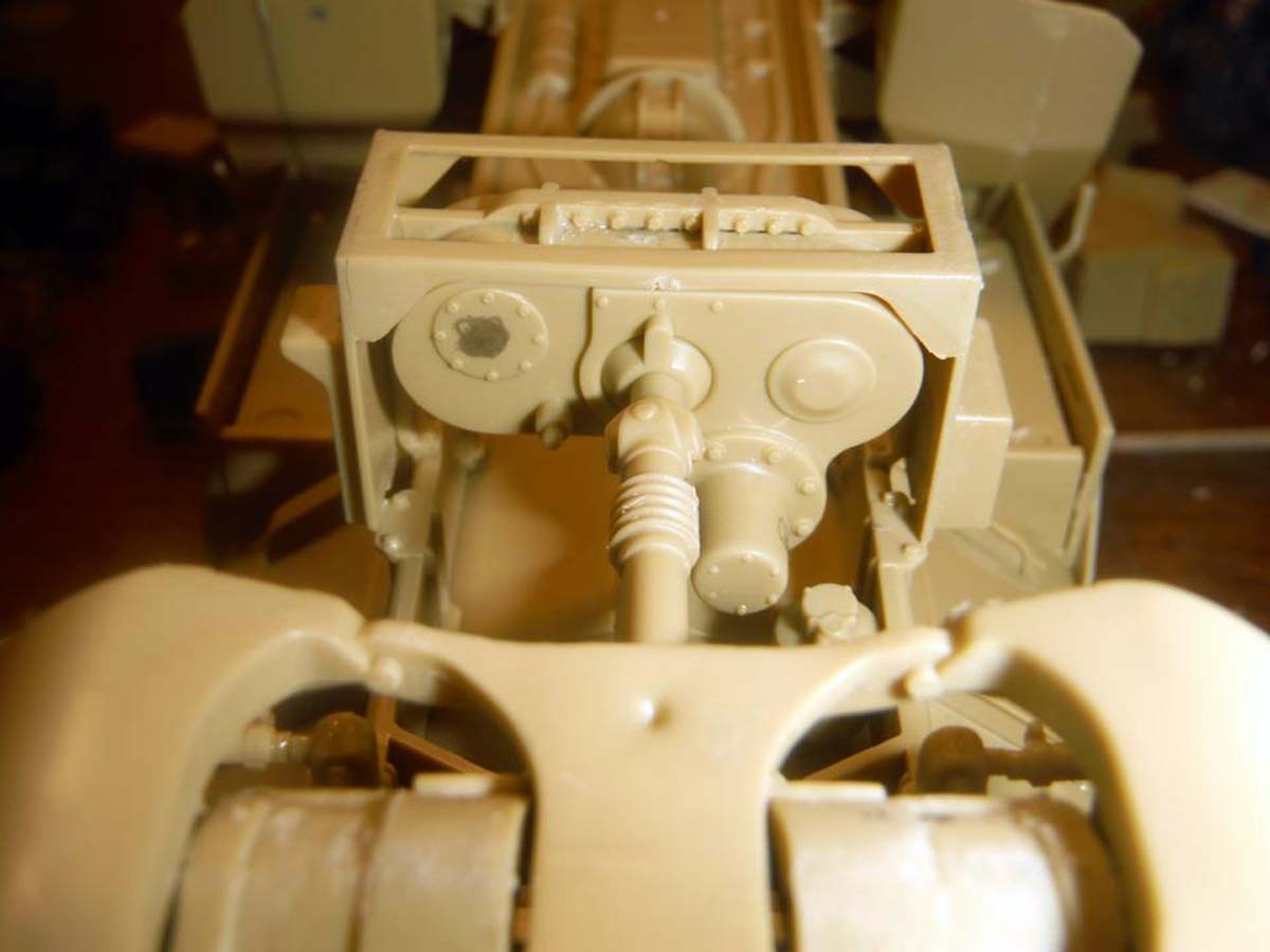
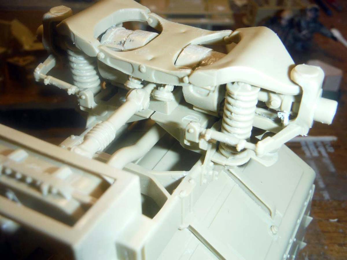
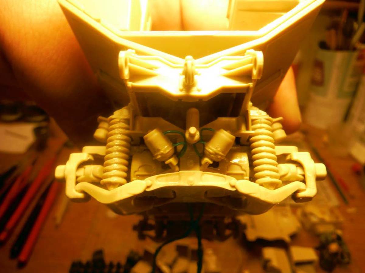
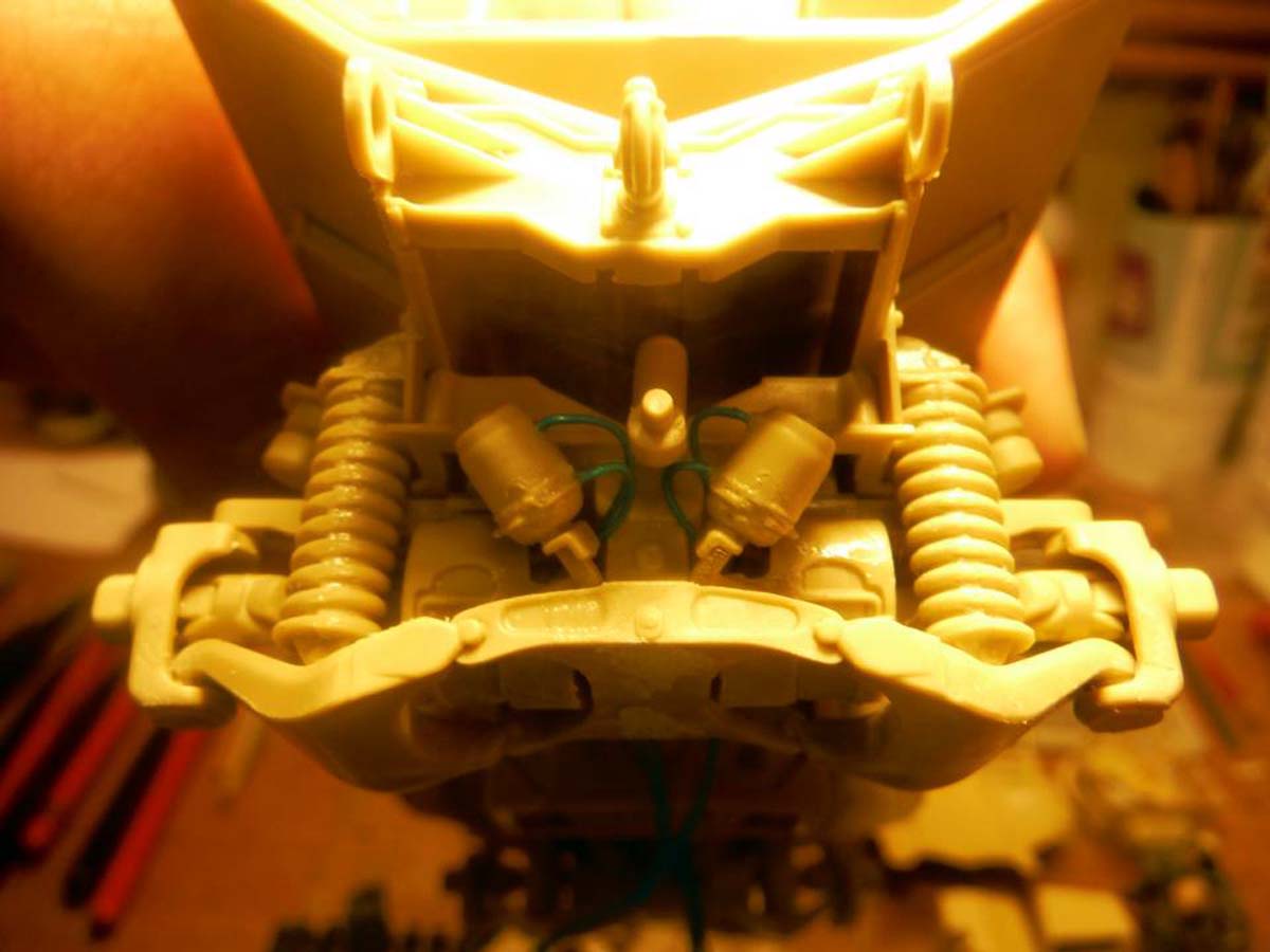
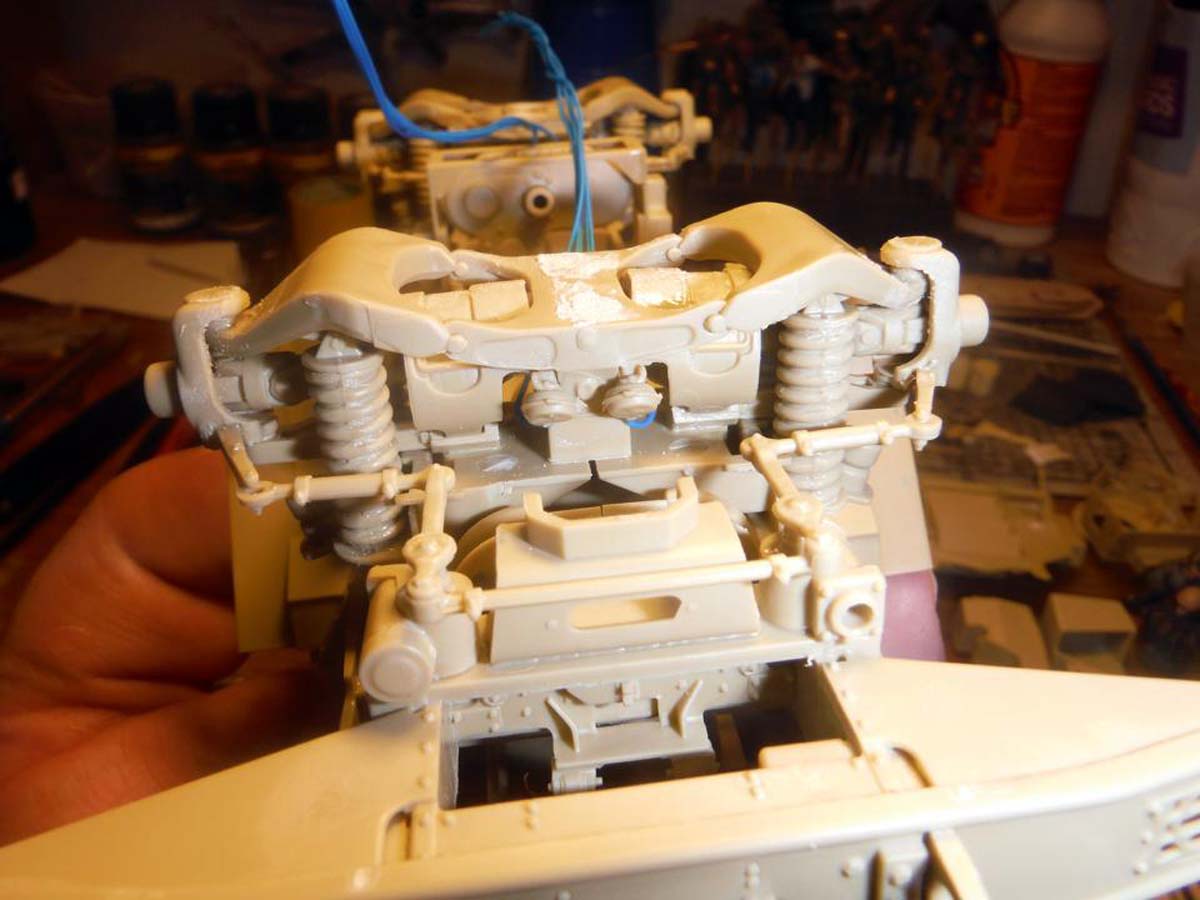
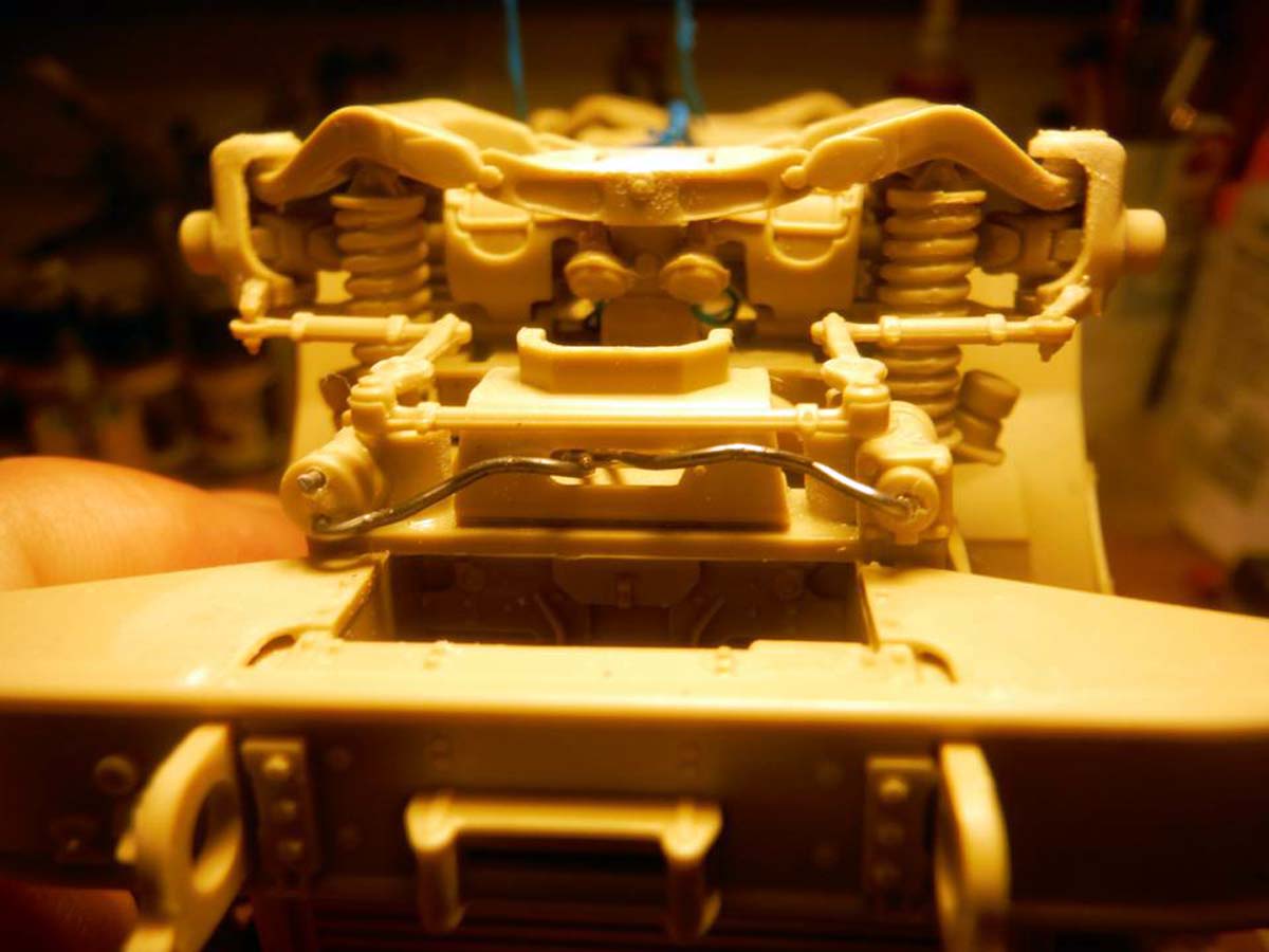
In Steps 4, 5, and 6, you are attaching all the parts to the frame such as suspension, axles, and muffler and such. I left some assemblies off for ease of painting and ease of adding hoses and cables. The muffler and bottles on both the left and right center were left off. Air hoses and brake lines will be added later along with other hoses and cables. In Step 5, I didn't add Parts B29, B30, and B36 because they attach to the upper hull, so that will be added after the upper and lower hull are mated.
****NOTE: There are NO differentials on the axles. Don't know how this can be fixed without some major scratch building and or surgery.****
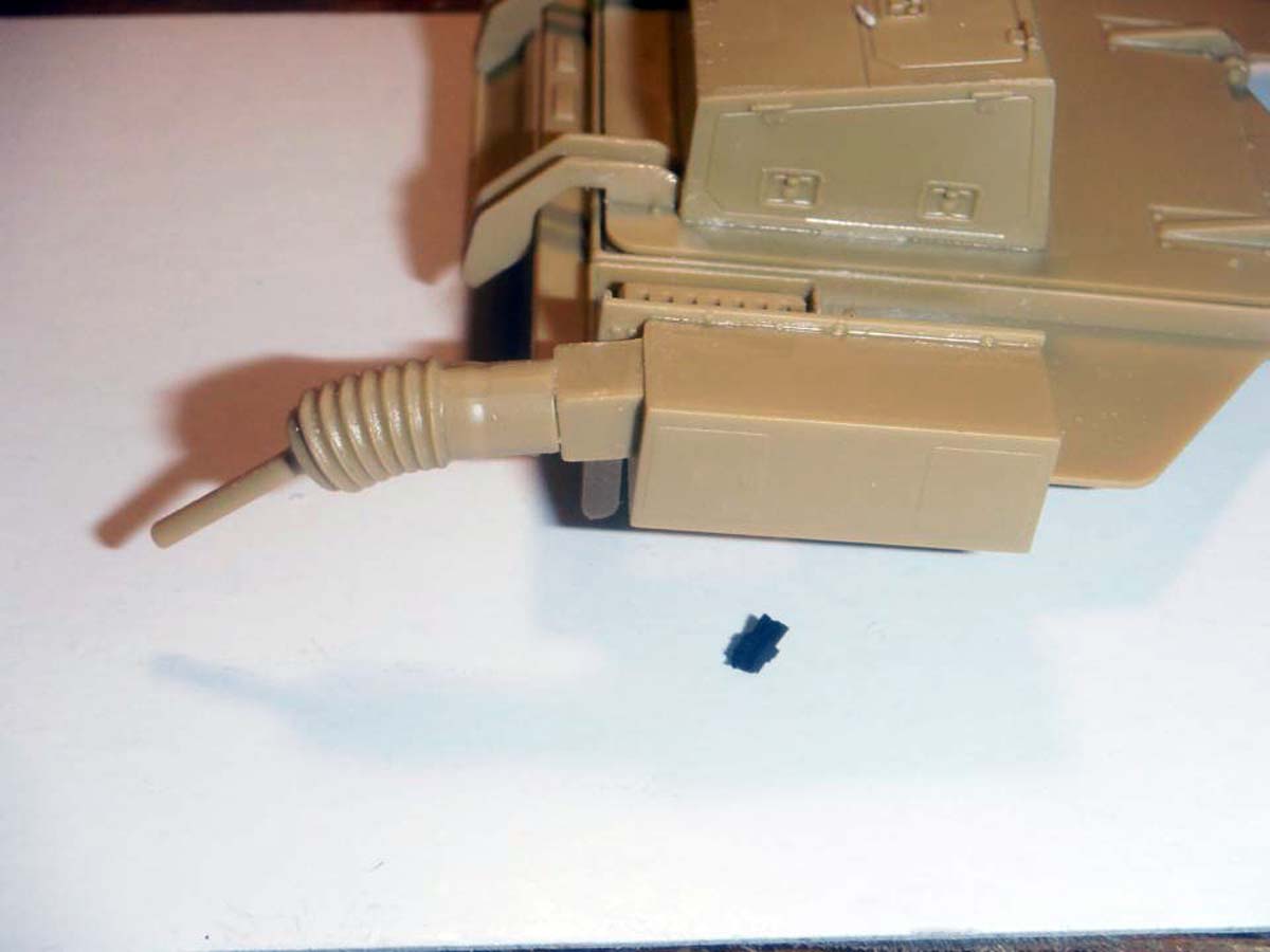
I went ahead and added the bumper in Step 7. I only left of Part C11 and C12 along with the clear parts GP6x2 for ease of painting the clear parts.
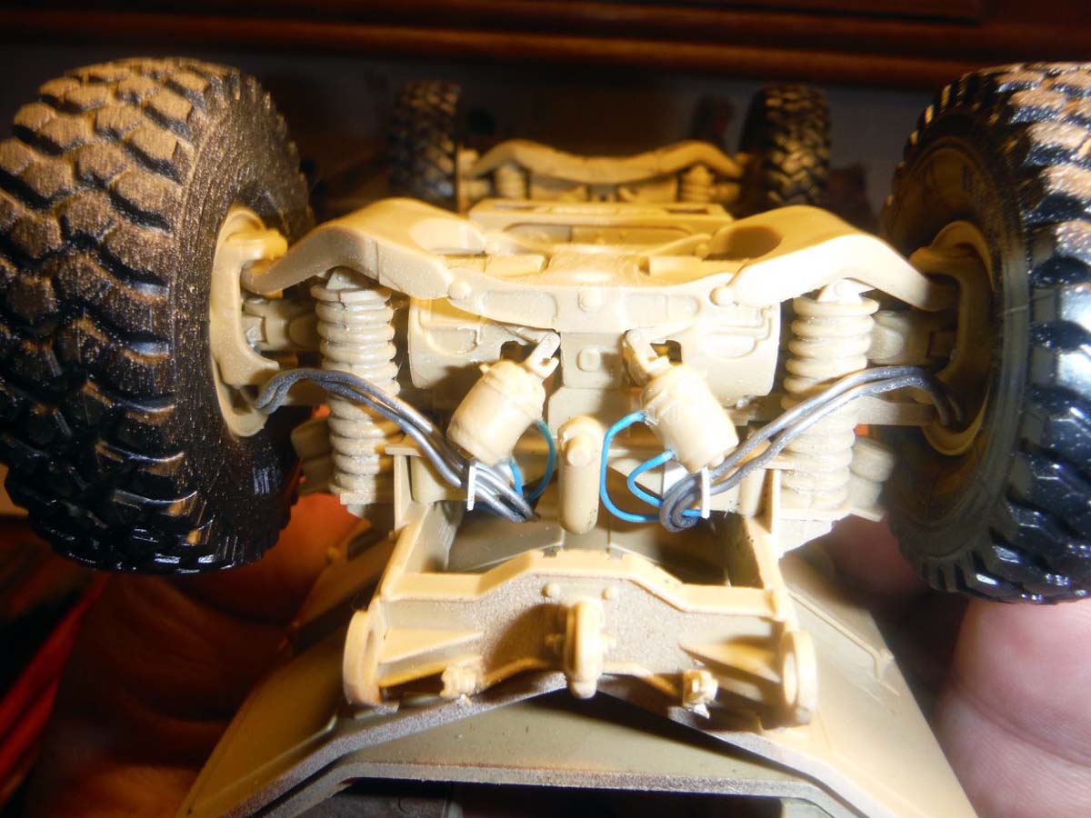
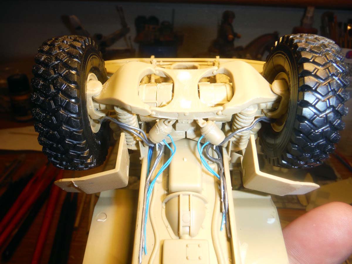
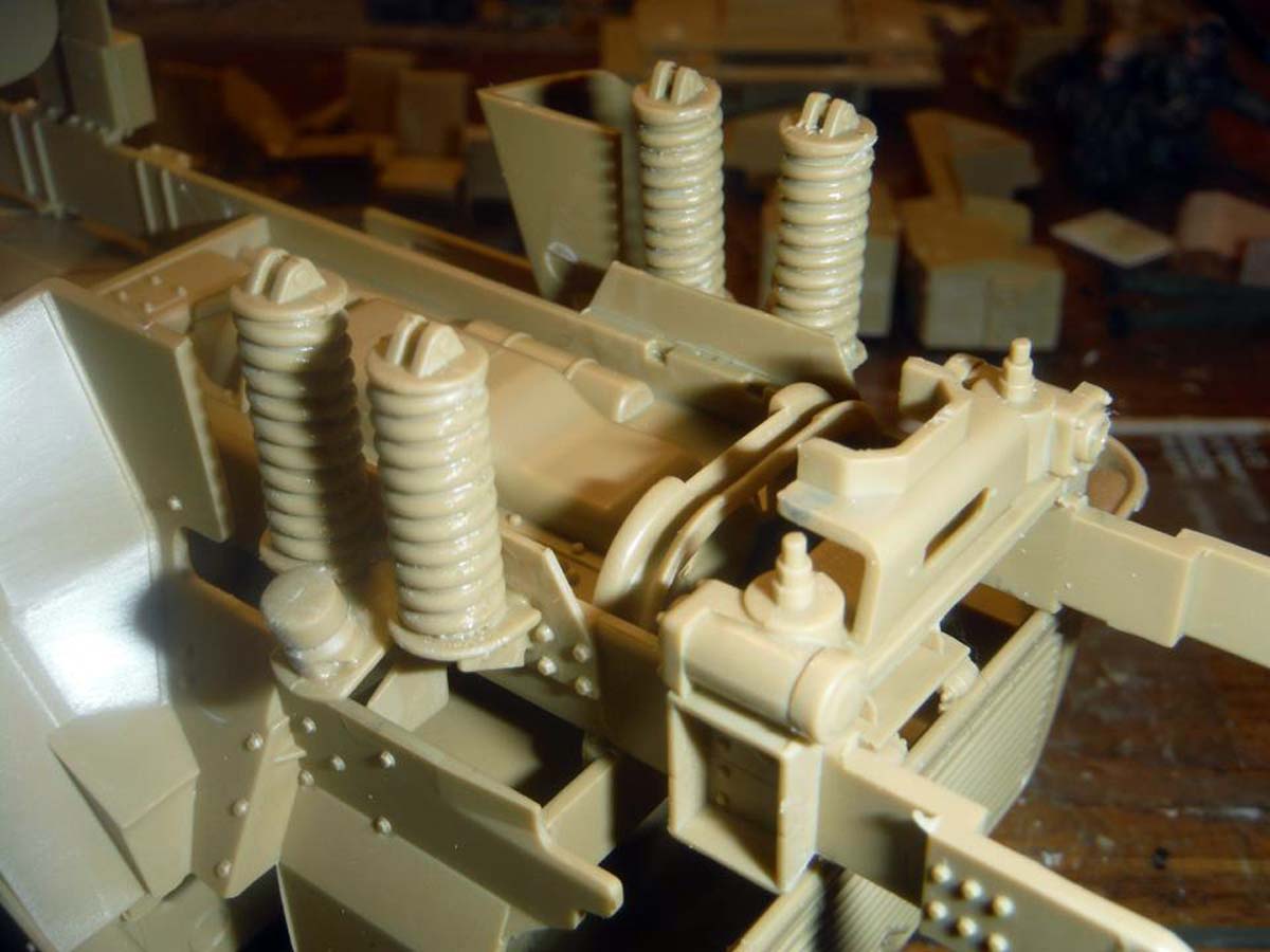
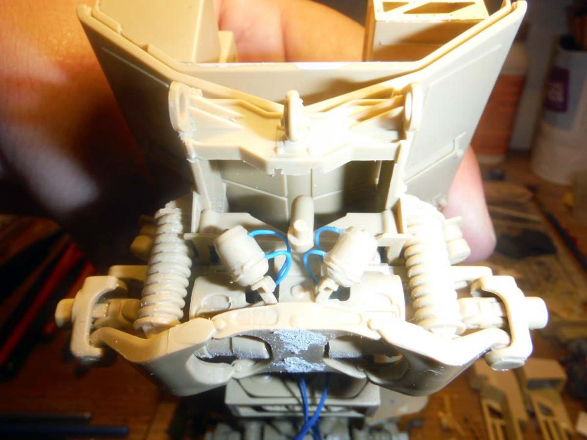
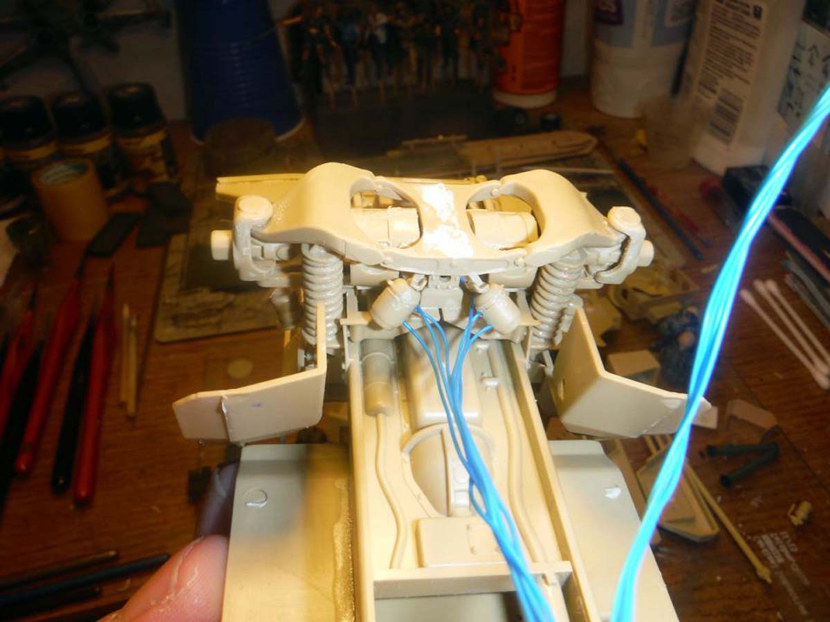
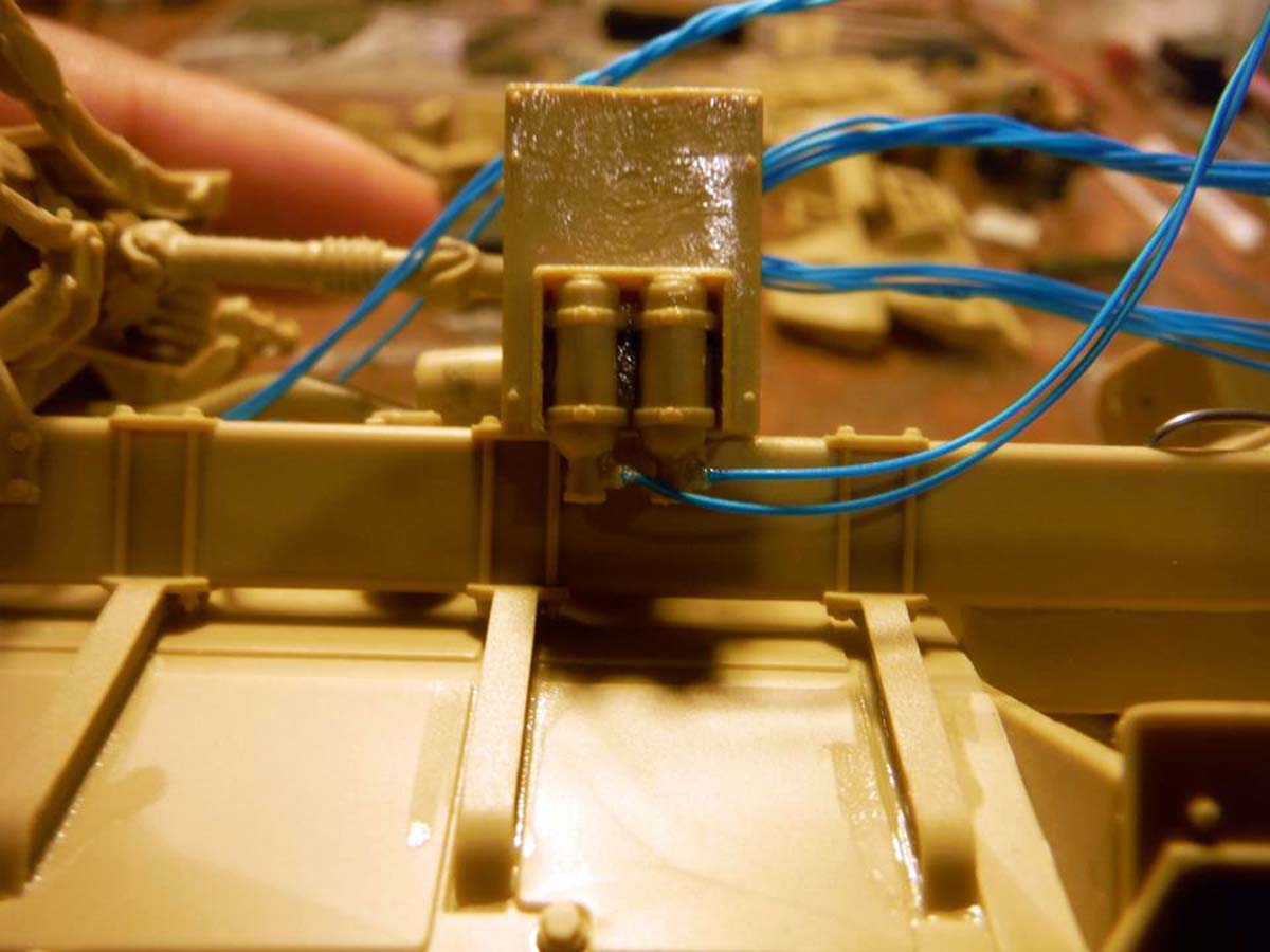
While trying to figure out how I am going to do the seat belts and the harness/mesh behind the seats, I decided to jump around a little bit on the instructions and get other stuff done. I added more hoses to the vehicle frame, this time to what I think is the fire suppression system bottles for the wheels. I also added the hoses that go to the steering modules. Next for the underside was the brake lines to the wheels and the fire suppression system hoses.
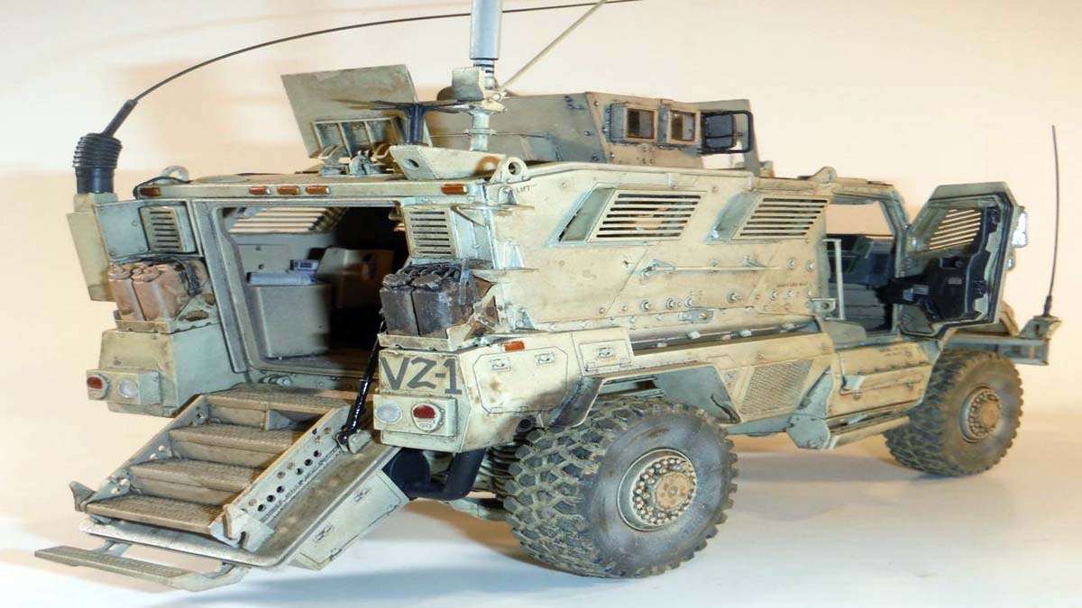
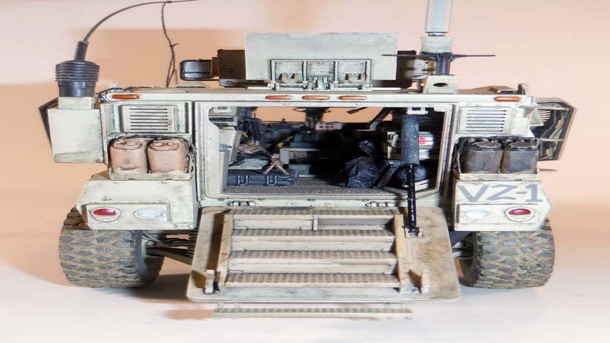
The rear ramp is movable, but it locks in place when closed. Parts B21 and B22 locks onto Part B17 when the ramp is closed. If you want to open the ramp from the closed position, you would have to reach in the rear roof hatch, and apply a little pressure up on part B17 to release the ramp. With a little work, you could make the locks on part B17 movable by cutting off the lock on B17 and drilling holes in them and sliding them onto round plastic stock.
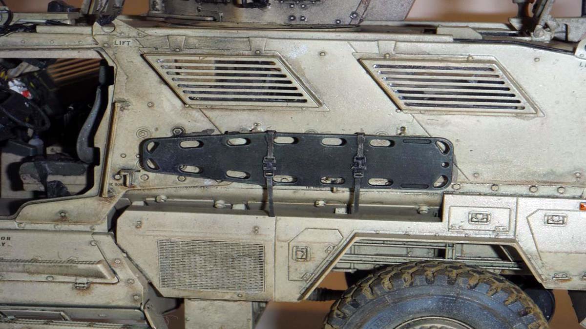
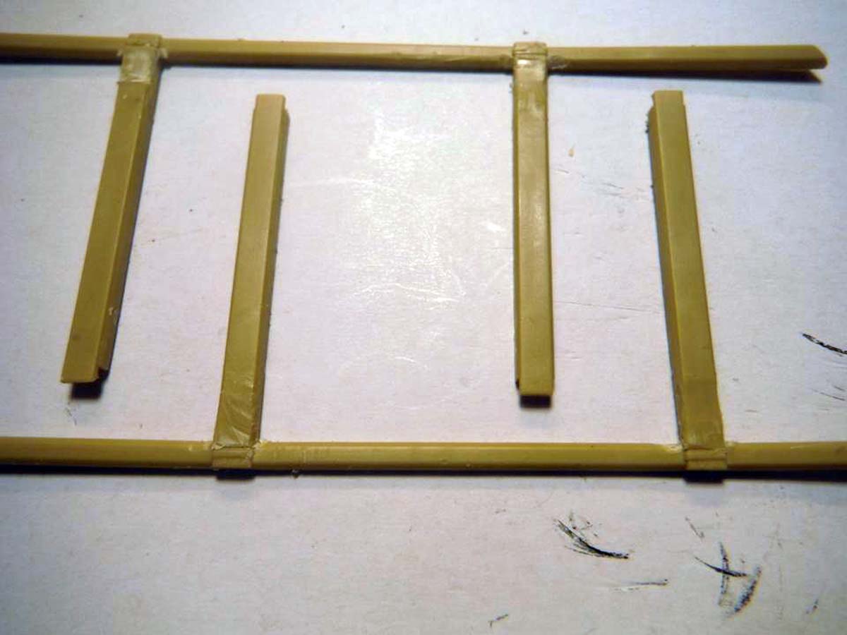
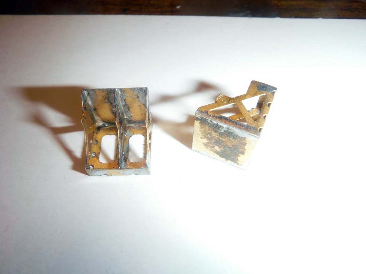
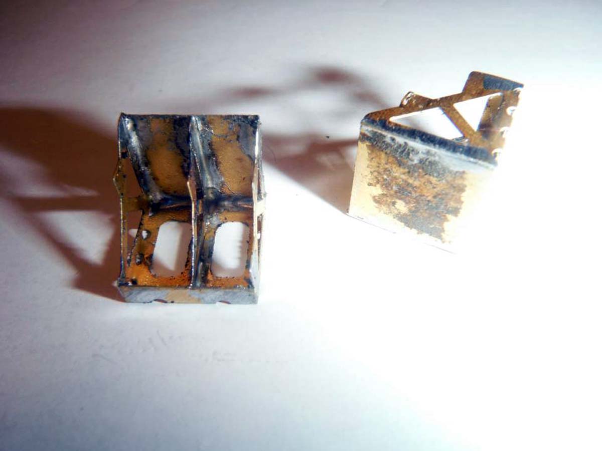
I decided to use solder on the rear photo etch fuel/water can racks instead of super glue. it was really easy to do since the parts bent perfectly. The only issue with these photo etch racks was the slits for the tie down strap. They had a little bit of photo etch in the middle of the slit and was very difficult to cut away without damaging that area. I tired one side and decided to leave it alone and figure out how to add the strap when it comes to adding the cans.
As I mentioned above, there is a major issue with this kit. The Maxxpro DASH DXM kit, Im sorry to say, is not a Maxxpro DASH DXM, but just a Maxxpro with some DASH DXM extras. After going back and forth with pictures from Robert Skippers excellent CD walkarounds and pictures from the WWP Maxxpro book, I concluded that the kit is not a DASH DXM version. While the outside of the vehicle looks like a DASH DXM, its the interior that is incorrect for the version. The difference is the AC unit that sits right behind the passengers seat. The DASH DXM version has a lower profile AC unit with two distinctive conduits coming from on top of it and the addition to the AC/DC power converter placed on top of it. A small issue is the lack of spall liner that is all over the inside top of the interior, no seat belts and no mesh harness behind the seats.
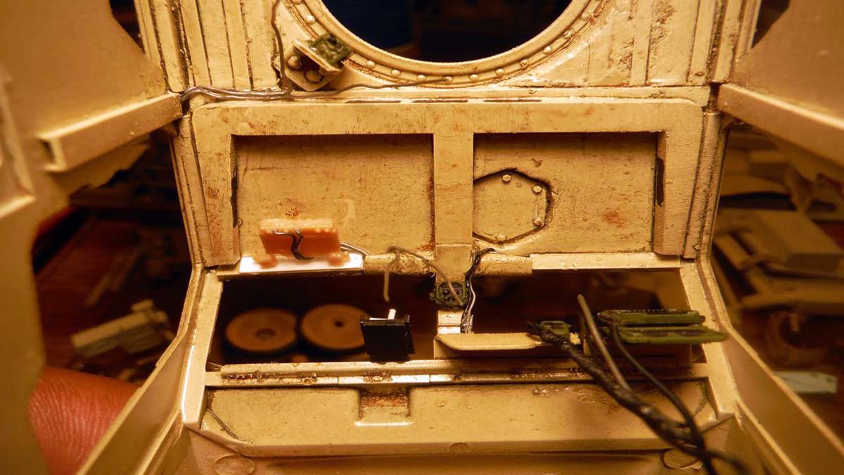
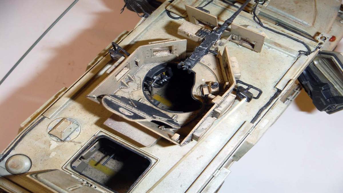
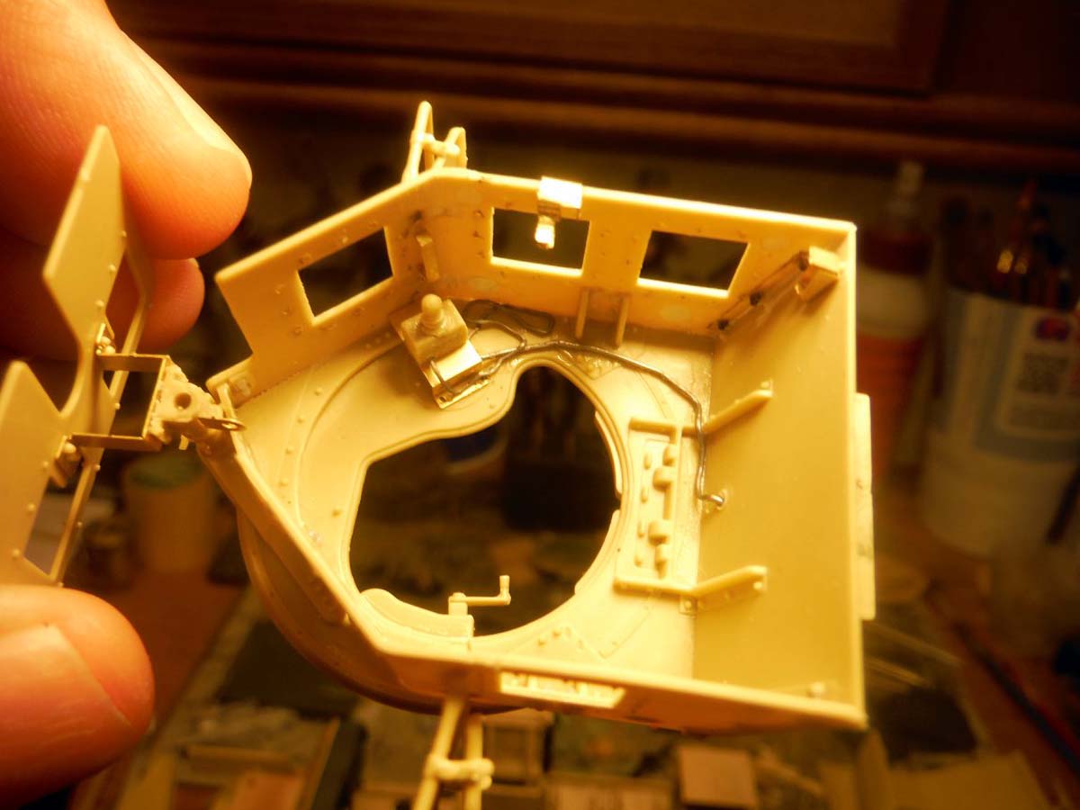
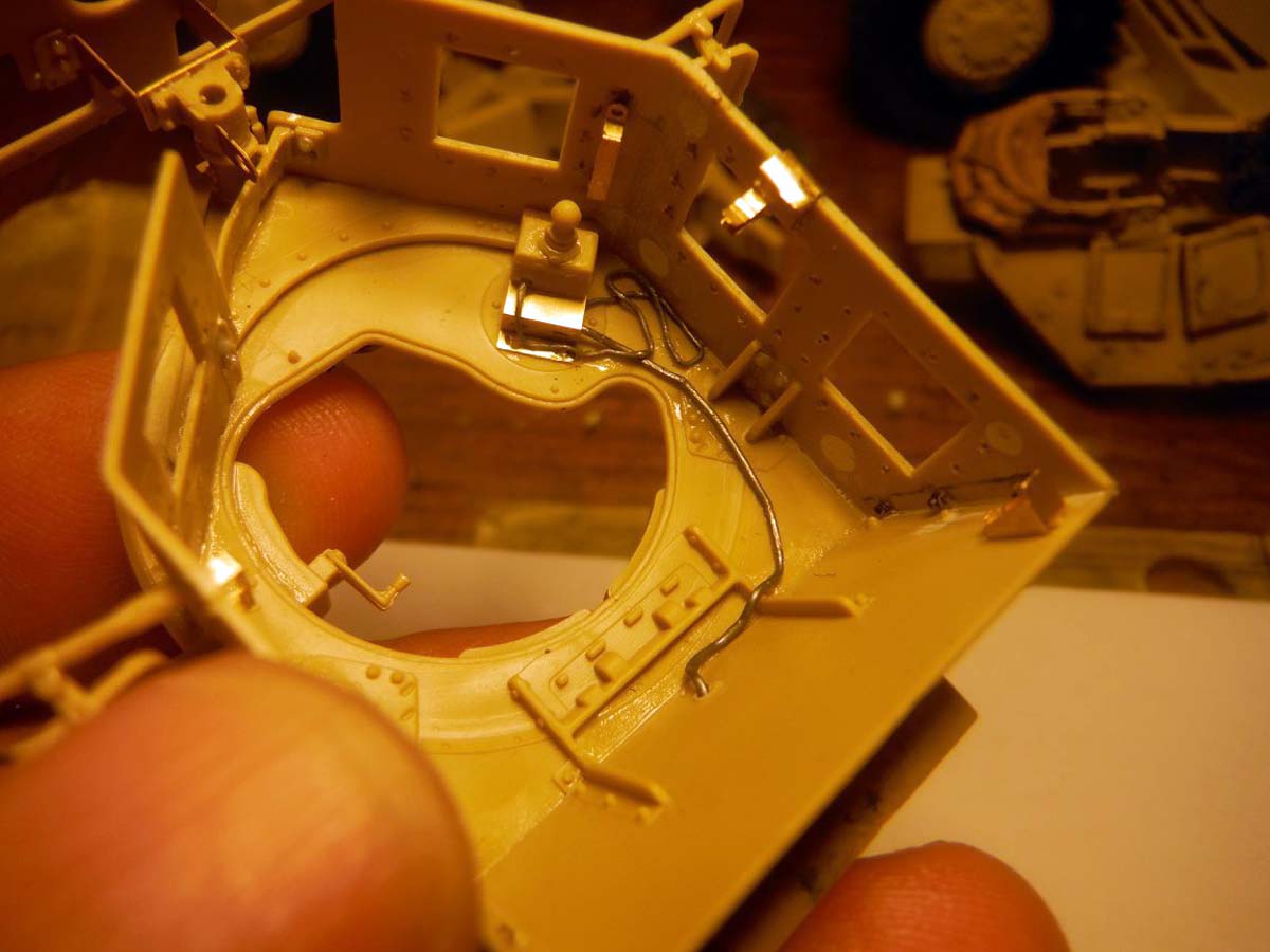
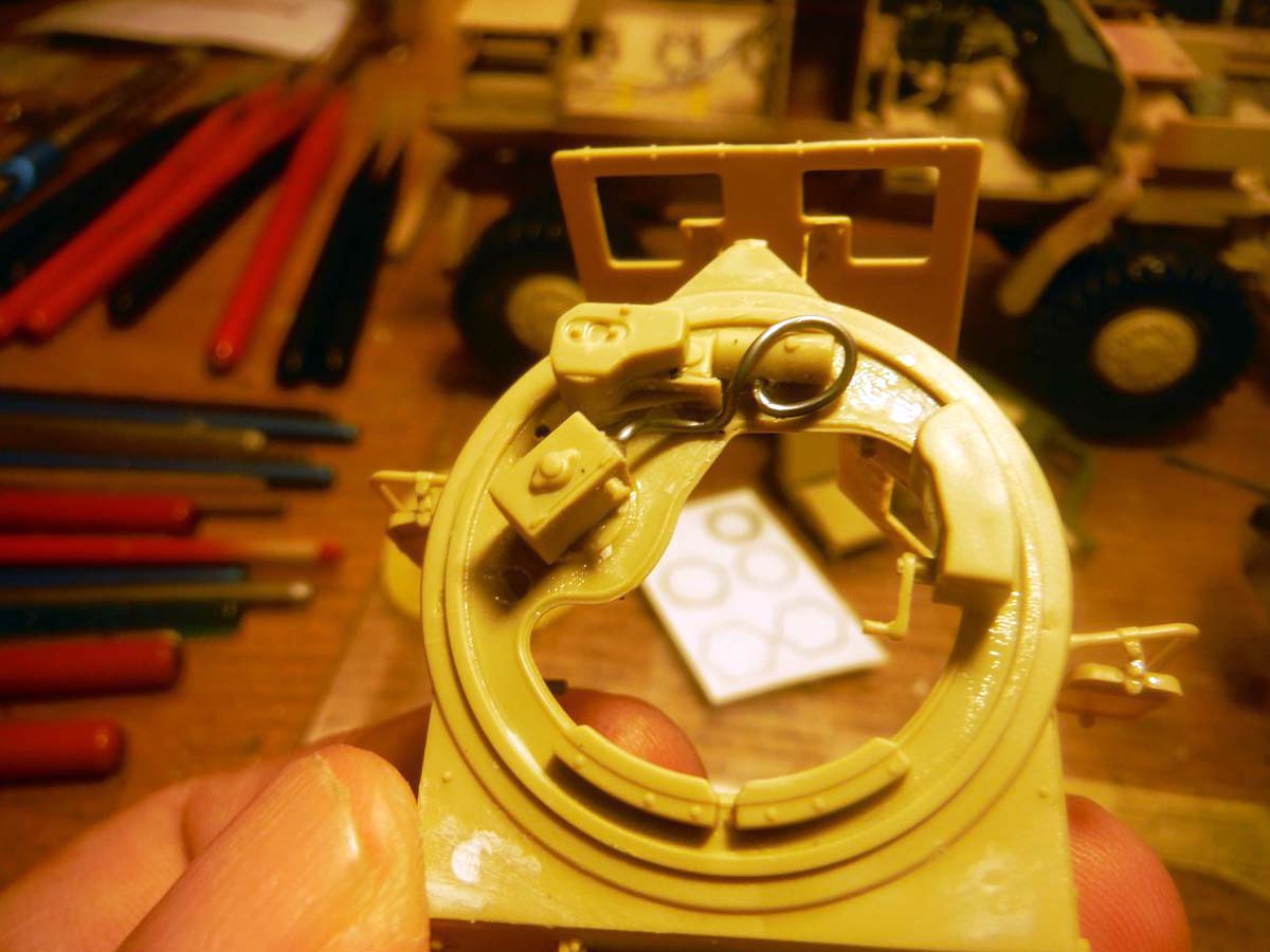
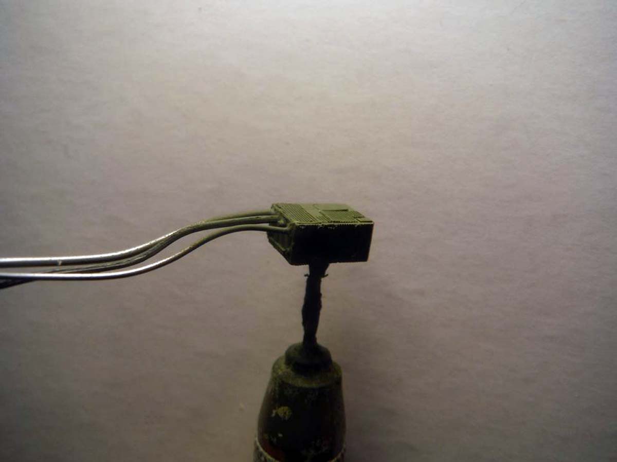
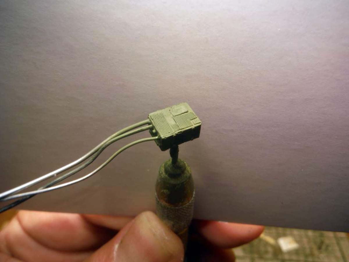
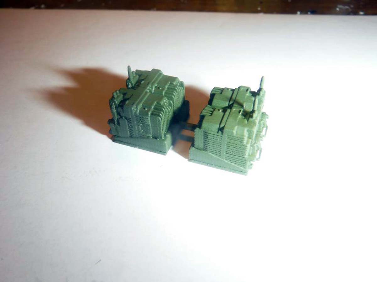
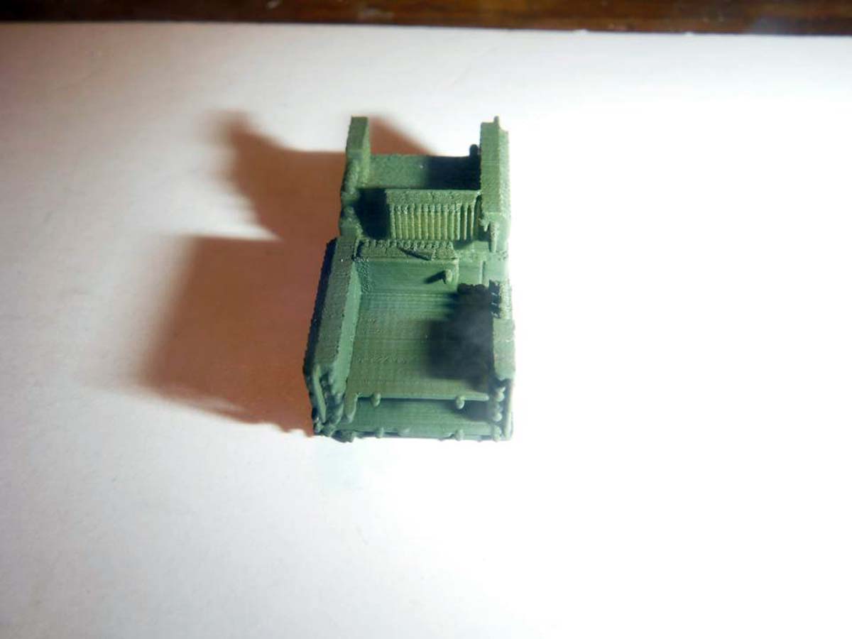
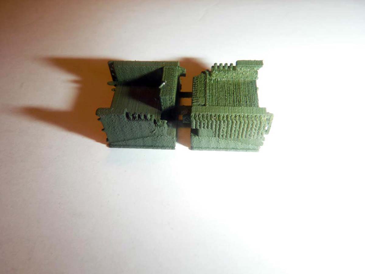
While trying to figure the major and small issue, I went ahead with the build where ever I could, in other words, I jumped around a bit. I jumped to step 15 and 16, the turret, since that could be completed as a sub-assembly. There are some punch marks inside the turret walls that need to be filled. A hole for the cable that goes to the rechargeable batteries in the rear of the turret to the turret control box needed to be drilled. Also, some nuts and bolts where added to the inside rear corners of the turret walls. Missing detail such as the holes that the bolts for the windows go through are missing on the inside walls of the turret. This was added by drilling shallow holes opposite sides of the actual bolts. I also added missing nuts and bolts in various locations. Also note that there was no locating marks or pins for the photo etch handles. I simply held the turret up to the light and marked the location associated to the locating marks for the mirrors. Two holes needed to be drilled in the circular plate on part M28 to accommodate the cables from the batteries and turret remote control. Thin lead wire was added for the battery cable and turret remote control. A cable from the turret control box to the turret motor was added. I added the small cable connector at the bottom of the turret control box with lead wire and plastic stock.
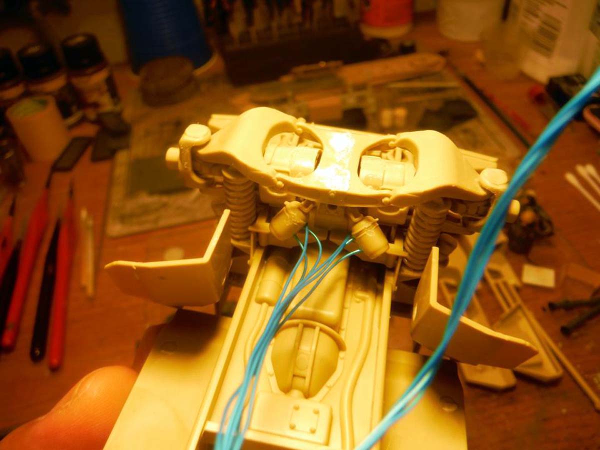
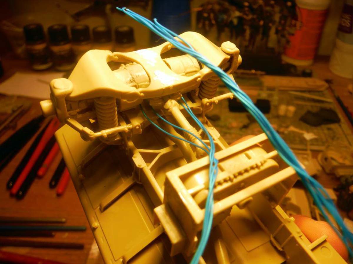
Another jump was adding the missing hoses for the tire inflation system to the axle frames. Zip ties need to be added to the hoses. I also rerouted and secures all the other hoses on the frame.
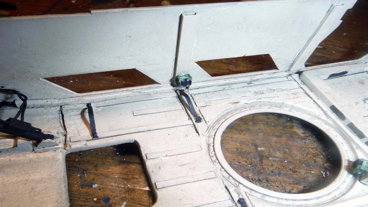
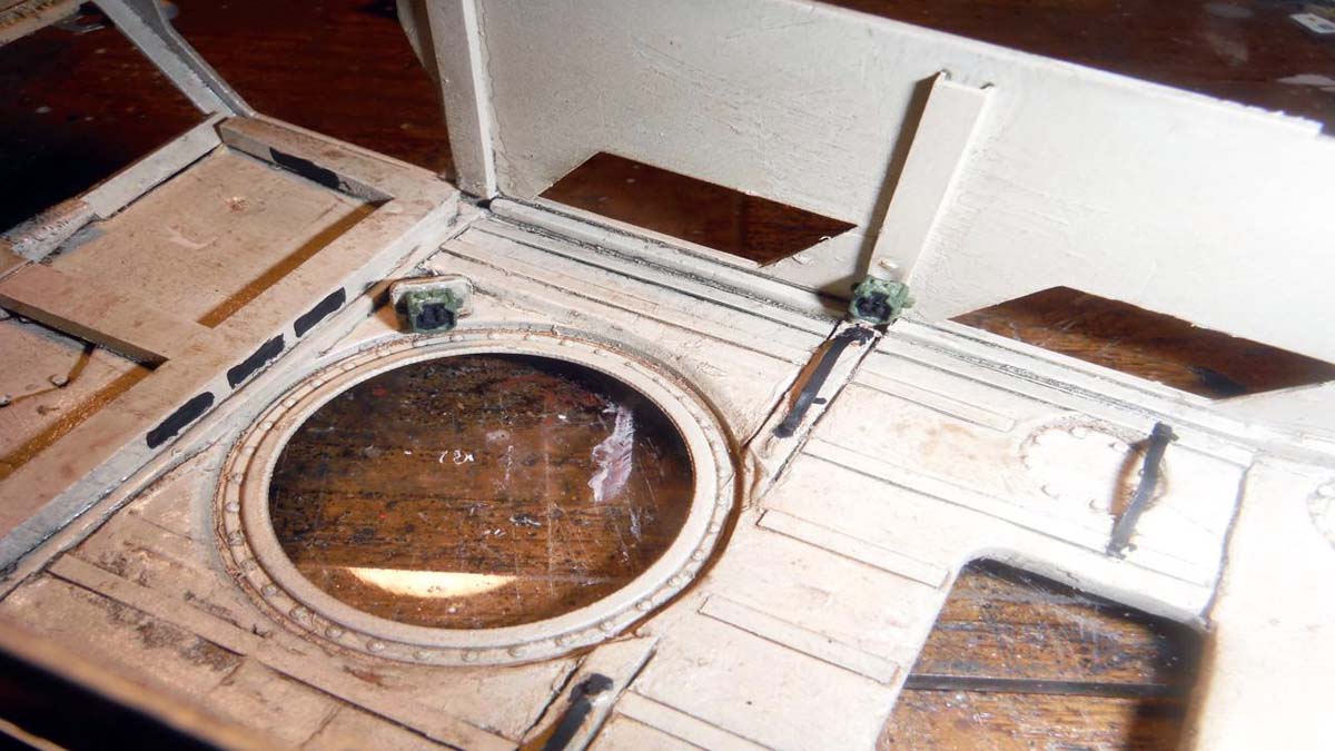
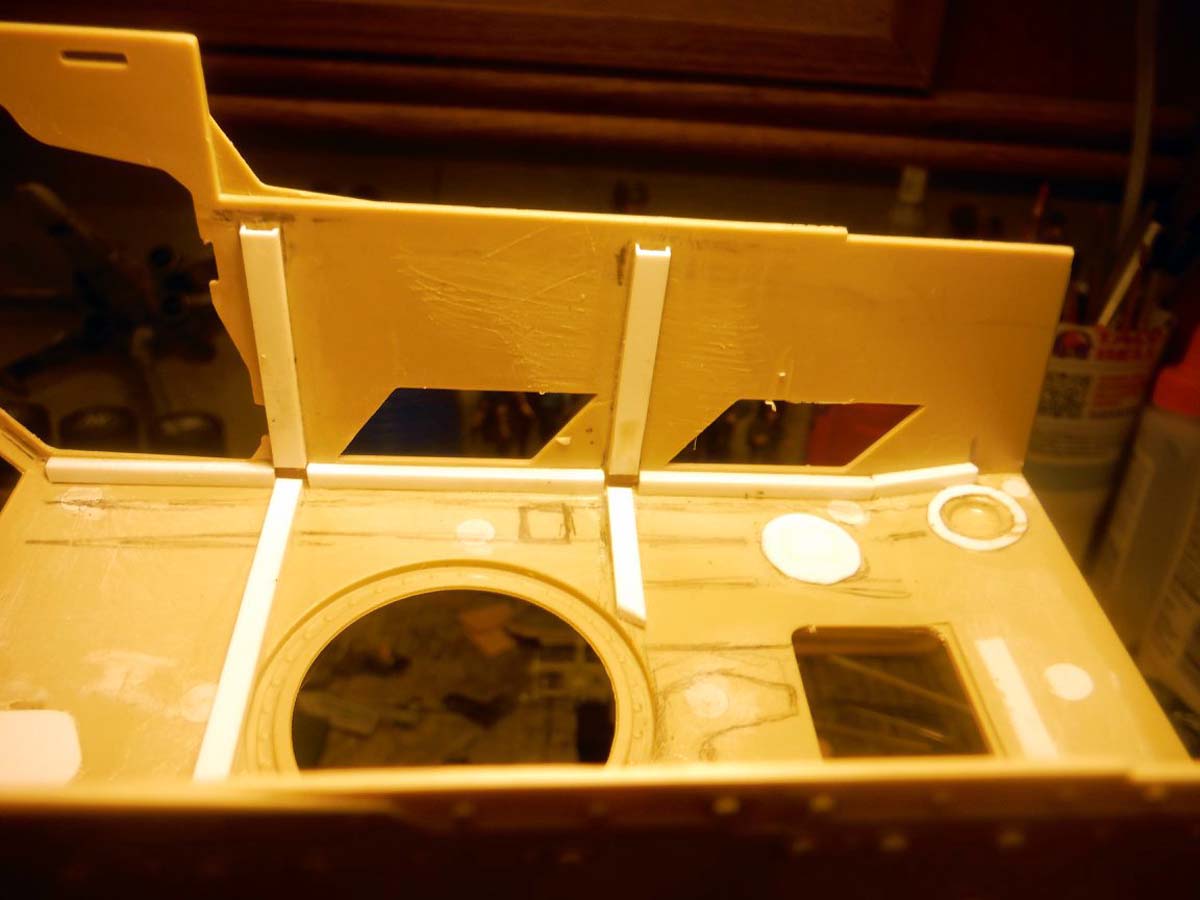
I started working on the spall liner issue by re-doing the cross-beam members inside. I also added the missing plates that correspond the other side. I used Milliput to simulate the spall liner. Nuts and bolts were added the plates. After everything was done and painted. I really didnt like how it turned out. I would suggest using plastic stock instead of the putty. Just round off all the edges to get the look.
Next was the seat belt issue. I was going to buy some Verlinden photo etch seat belt buckles, but because of the style of belts the MAXXPRO has, I was going to need 3 sets of them. So, I went ahead and scratch build the buckles out of very thin plastic sheet and Tamiya tape for the belts. I really dont like how they turned out, but with the vehicle all closed and just the doors and hatches open, they look ok.
Now the issue of the mesh behind the seats. The mesh is attached to a rope and ratchet strap system. Neither the ratchet system or the mesh is in the Panda kit. While researching for this build, I did find two pictures that helped in the decision of the mesh. In both pictures, the mesh and rope/ratchet system are not present. So, I decided not to try and replicate the mesh and rope/ratchet system.
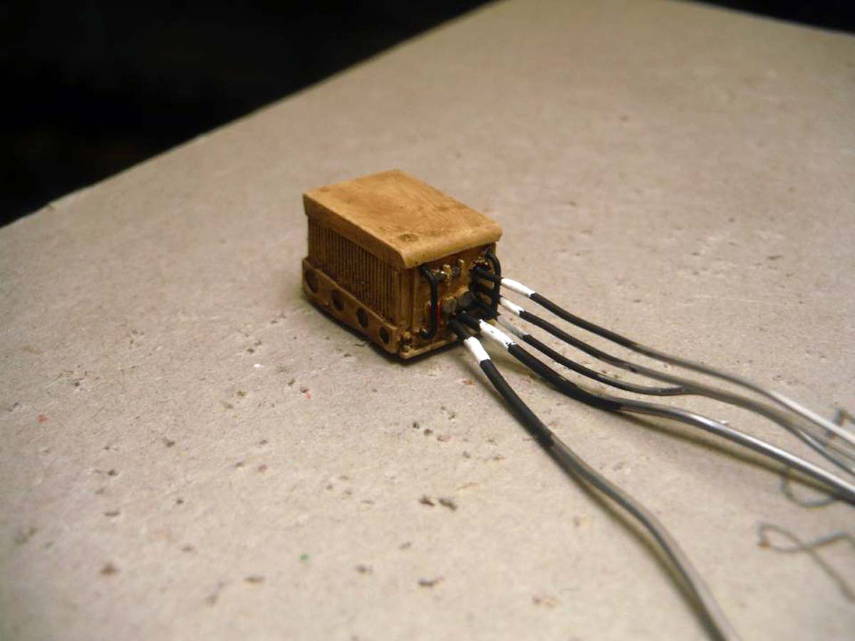
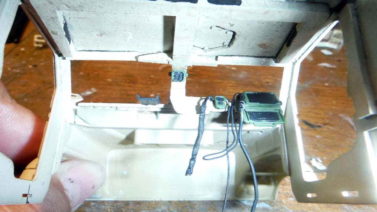
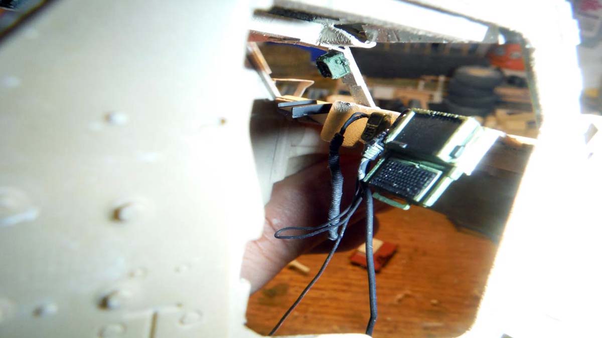
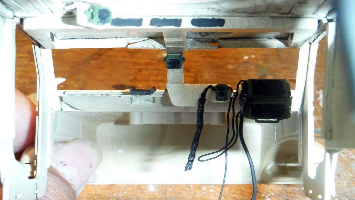
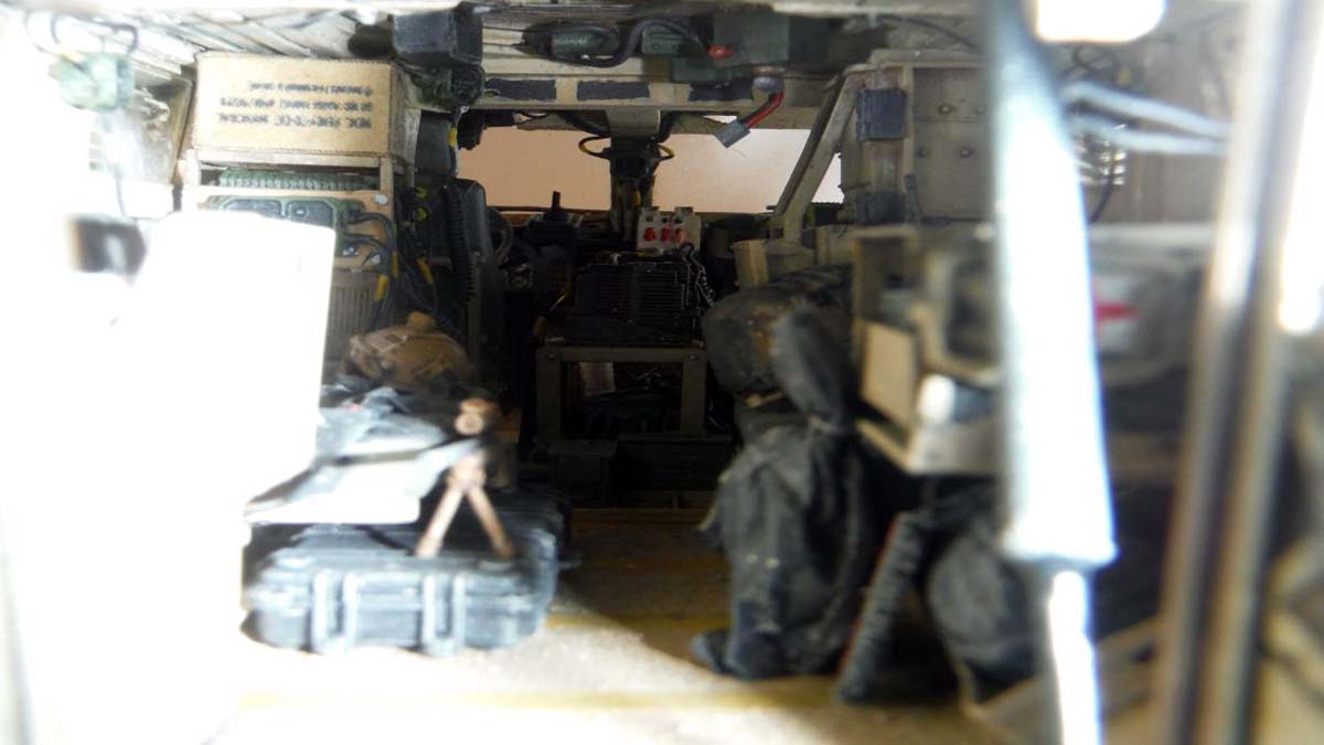
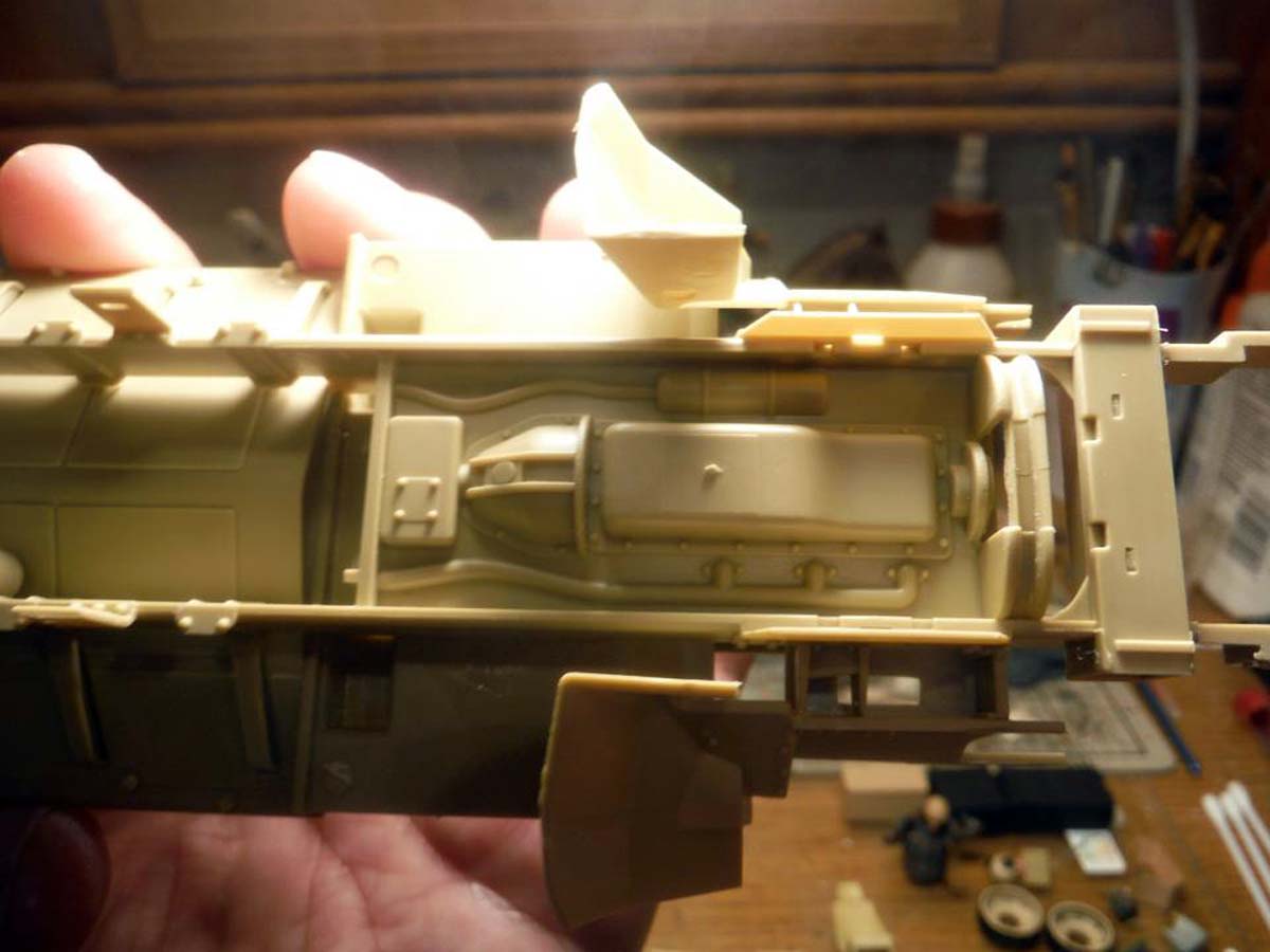
Last big issue was the AC unit that is located right behind the passenger seat on the right. In the DASH DXM, the AC unit has a lower profile and the Power Converter, that is usually stored in a side bin, is now located on top of the AC unit as in this picture. The air duct system is different in both Maxxpros. In the original MaxxPro, it was just on duct that was located between the front of the cab and the rear compartment. In the DASH DXM, the is two separate ducts, one to the front cab, and one to the rear compartment that runs down the center of the ceiling. Creating the duct system and AC unit would have been no problem with plastic stock, but because this is a feature/review build and I wanted to complete this in the time frame that is in the review rules, I decided not to. One more thing that is/was missing from this kit that is noticeable from reference pictures, is the fire extinguishers that is located in the rear right of the vehicle. These fire extinguishers are part of the fire suppression system. Again, this can be replicated by using plastic stock or spare extinguishers from other kits.
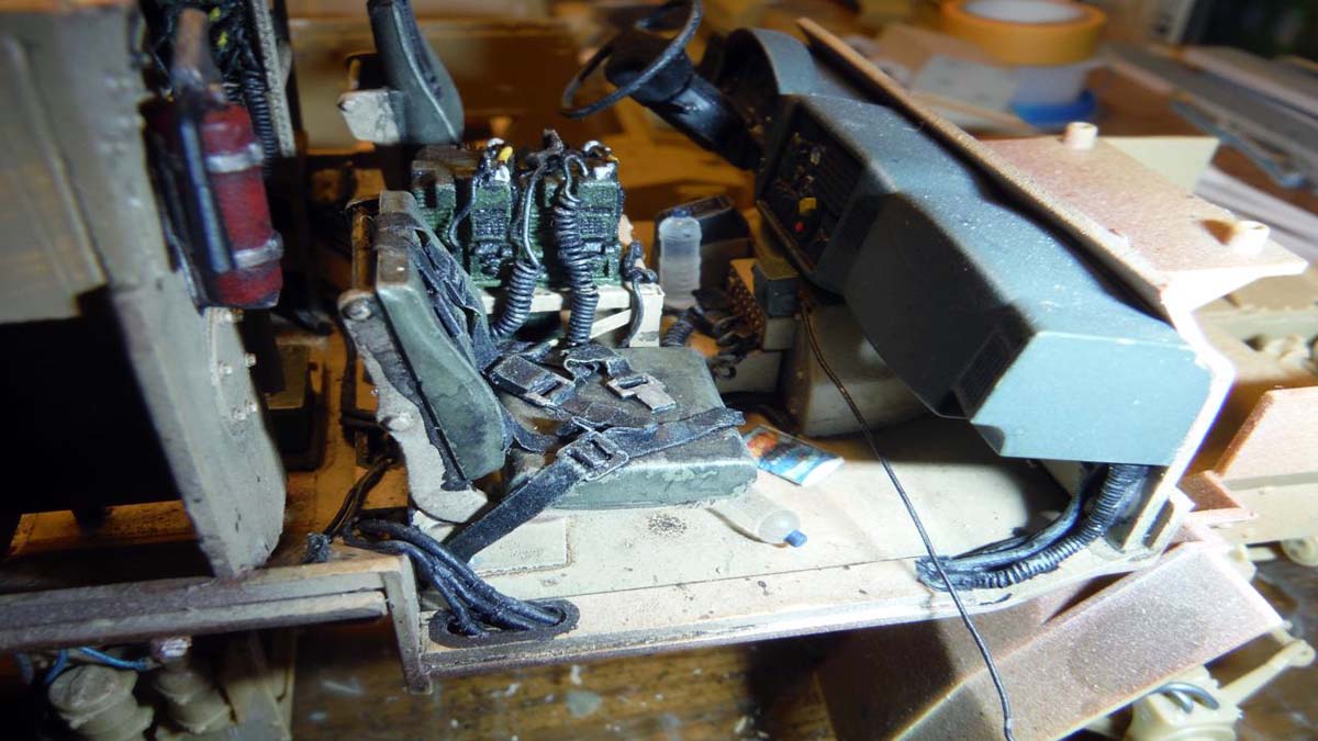
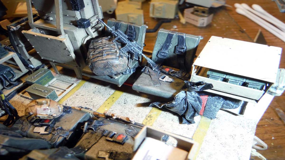
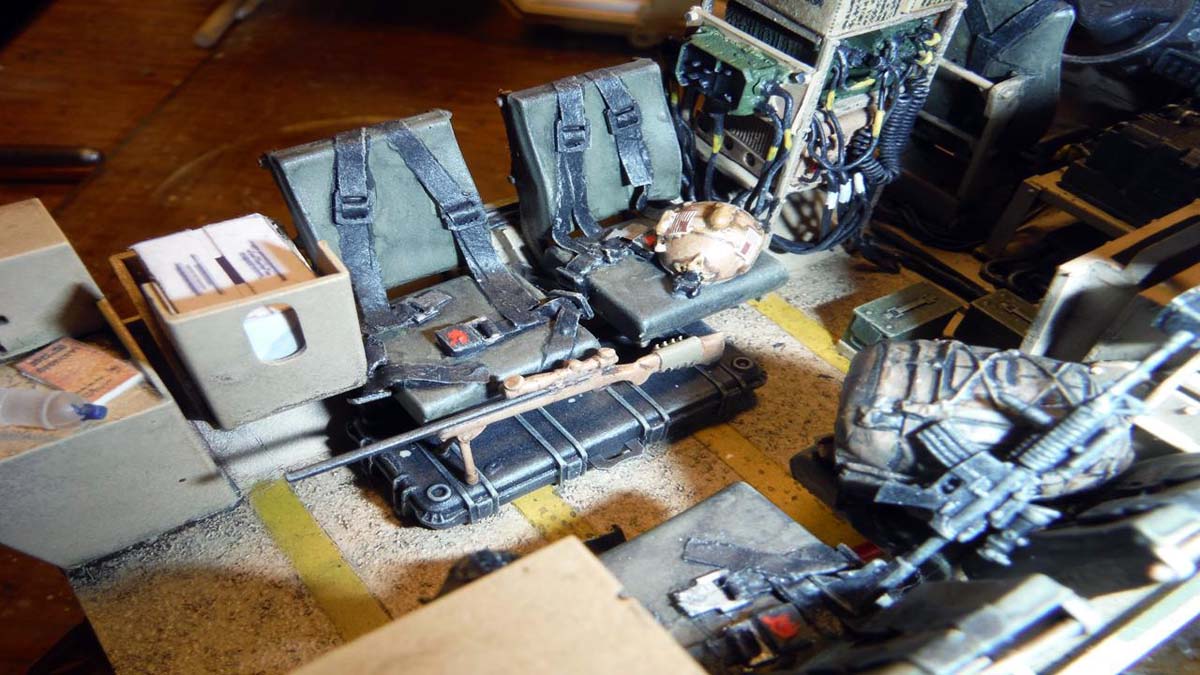
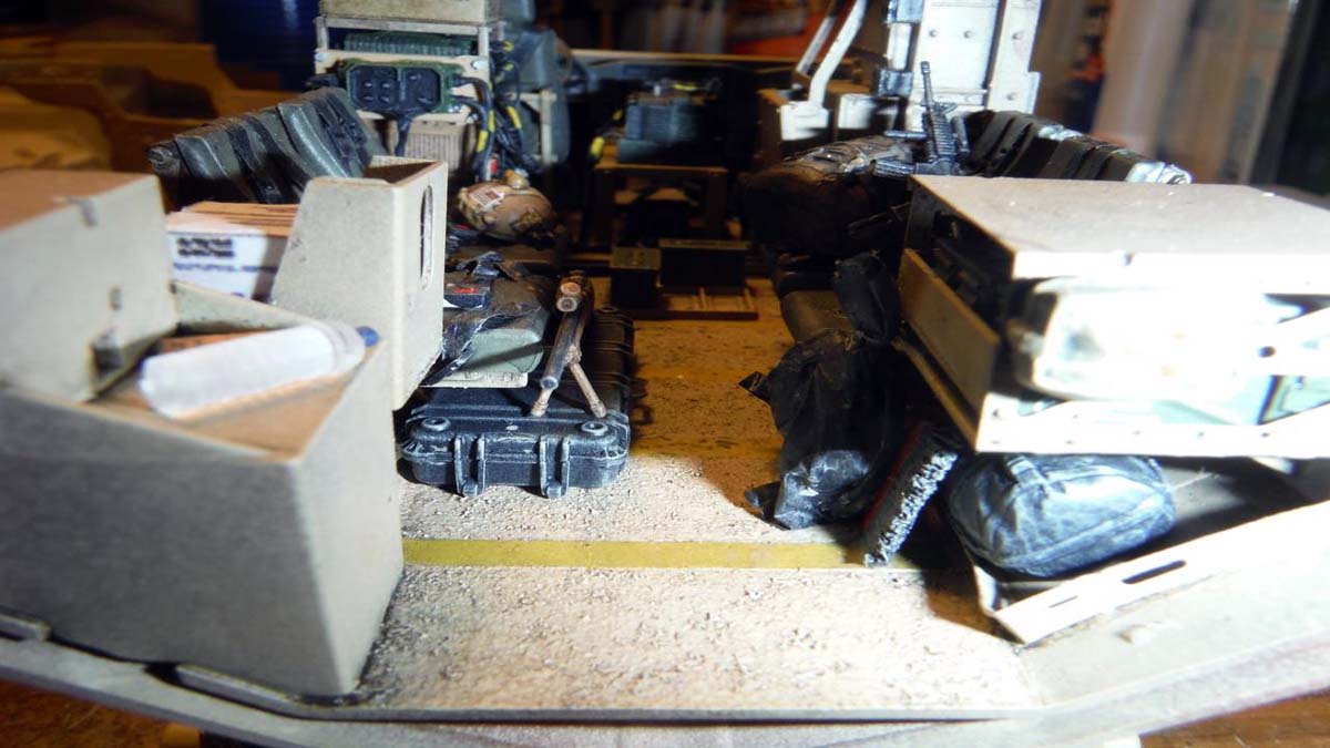
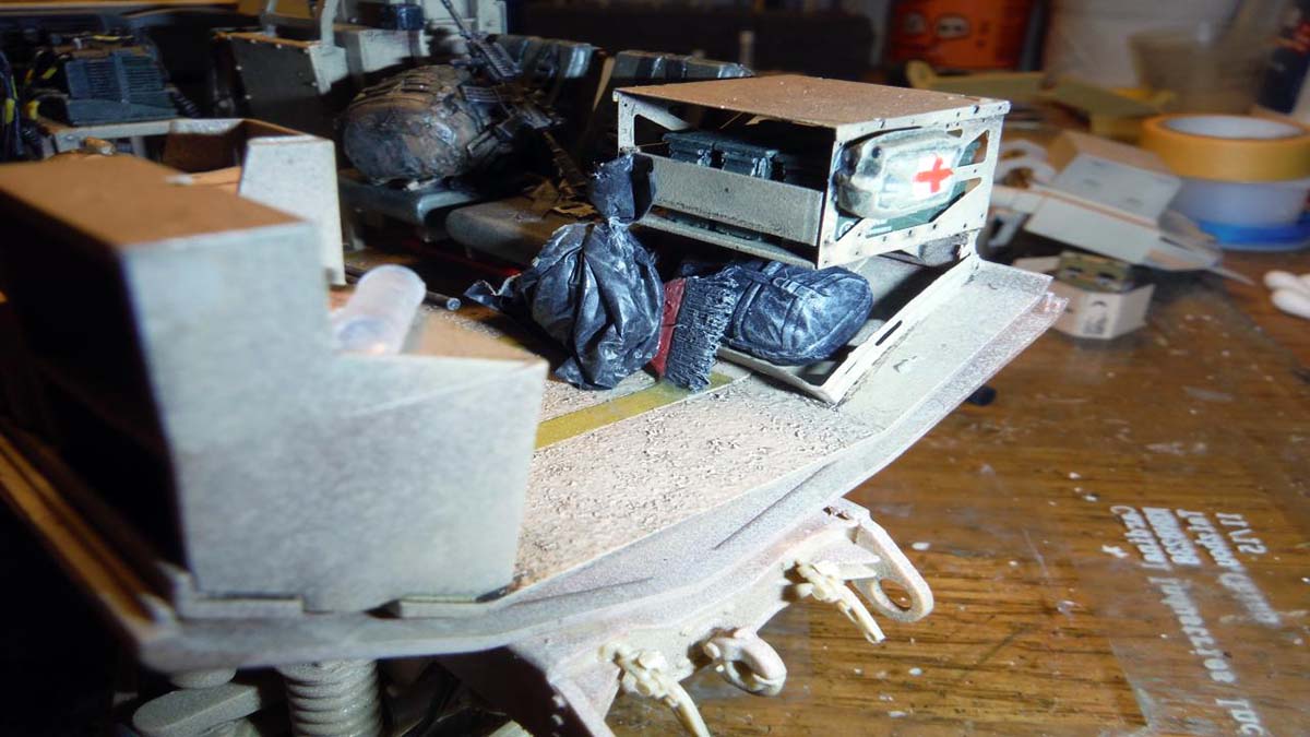
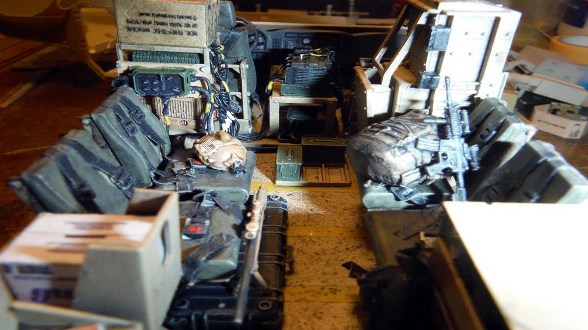
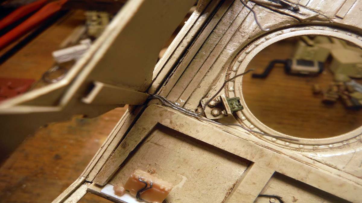
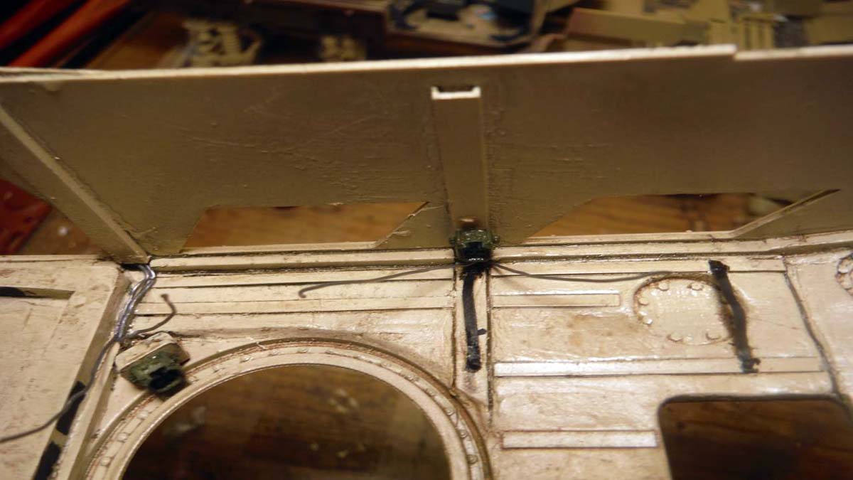
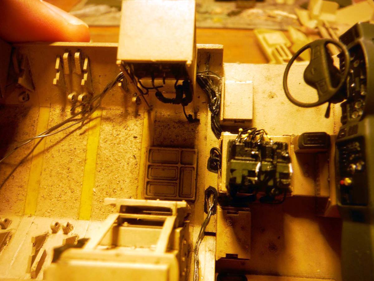
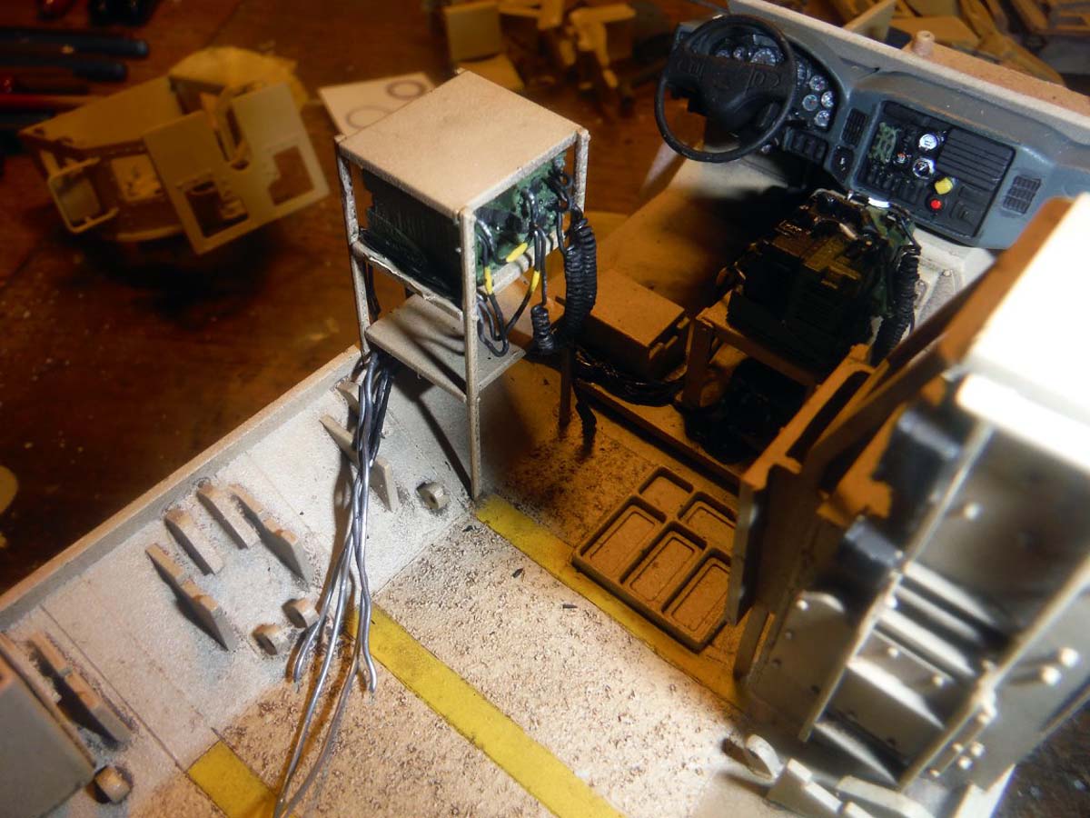
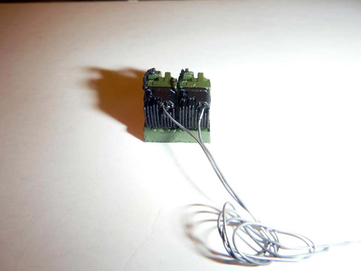
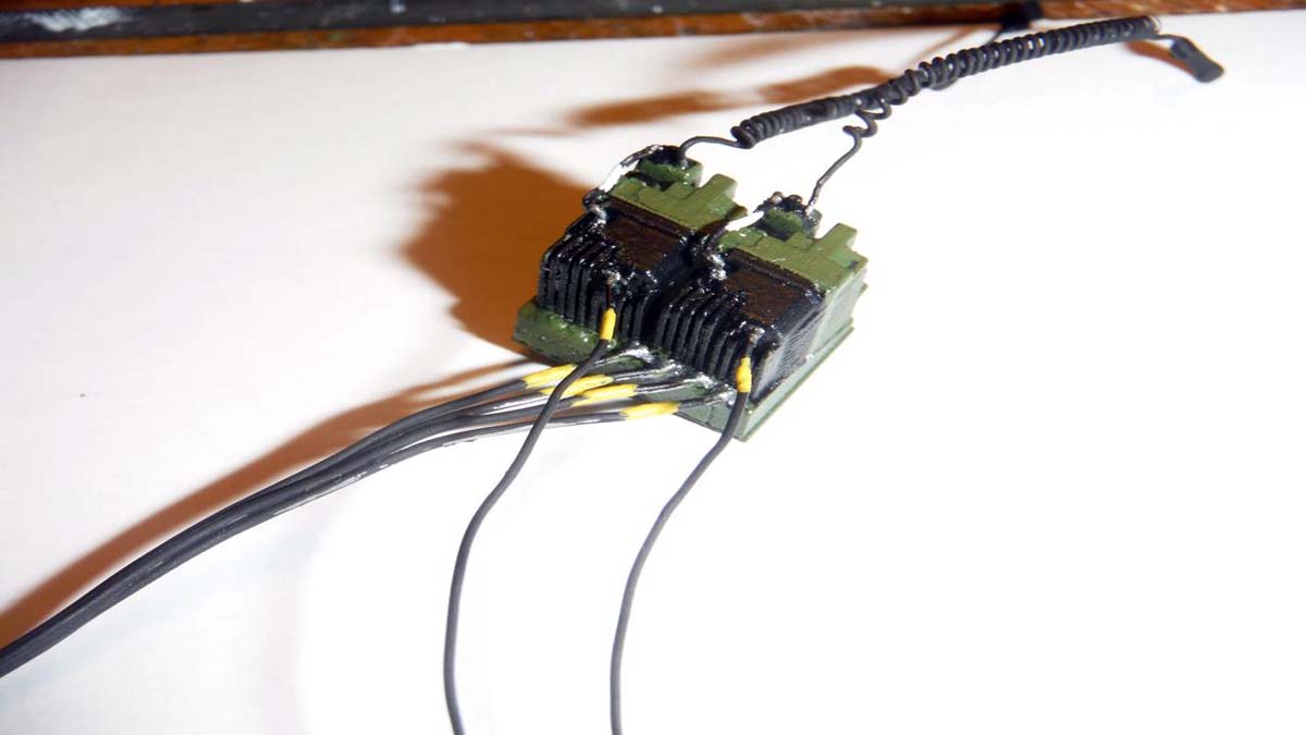
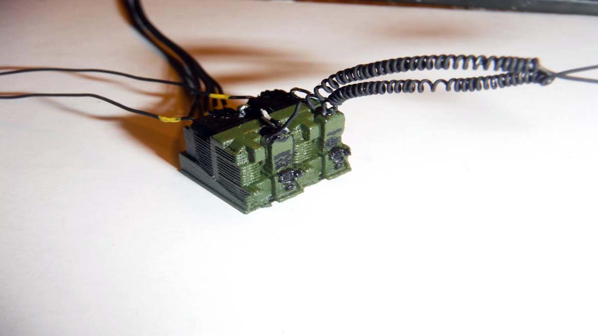
To finish up the upper interior, I added some Evergreen bits and pieces for the AC unit ducts and mounts for DVE joystick, FBCB2 monitor and PLGR, Fire Control box, turret gunner radio box. I was going to add the remote-control box for the DUKE anti-IED system, but totally forgot. At this time, I added the cables for the FBCB 2 screen, PLGR and fire suppression box. Last hoses added where the missing hydraulic hoses for the ramp arm. The "trash bag" came from a piece of thin black plastic bag that you get from the local gas station. I made the broom behind the bag from Evergreen stock. The sniper rifle is from Blast Models and the Ops-Core helmet is from Legend Productions. I completed the VIC-5 system by adding the control boxes to the upper interior. Once finished painting the inside of the upper hull, I closed her up and went back to finishing the exterior.
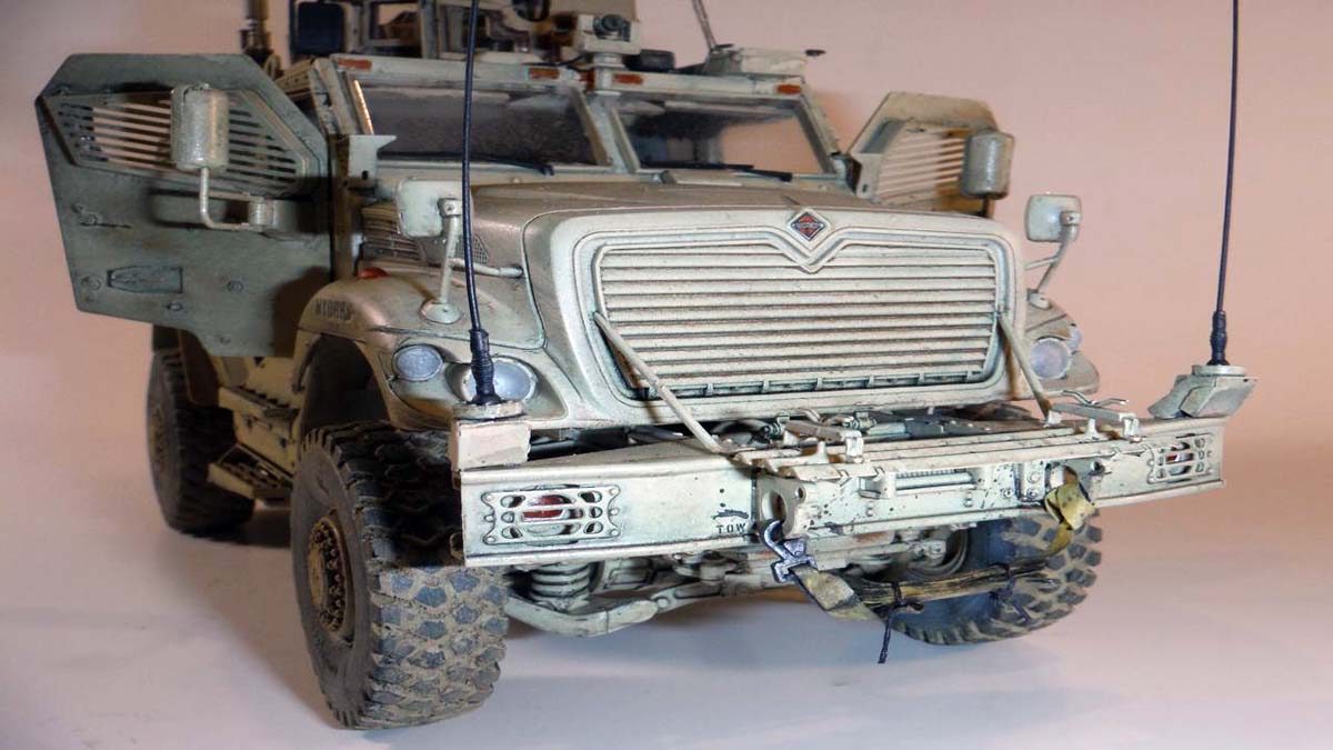
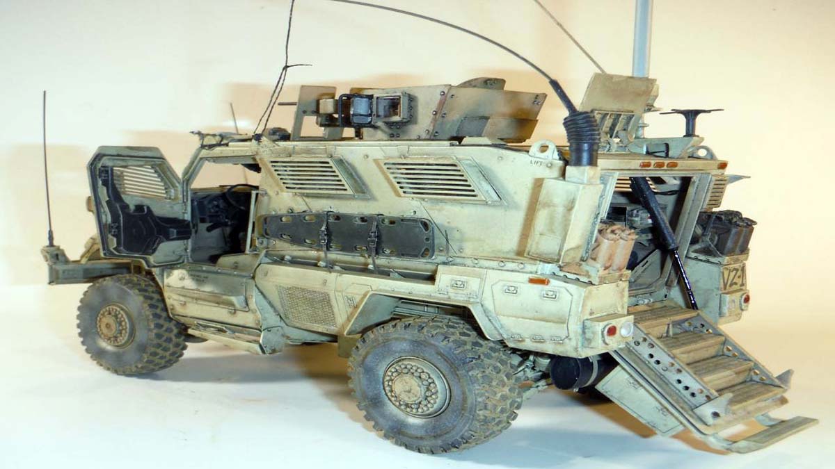
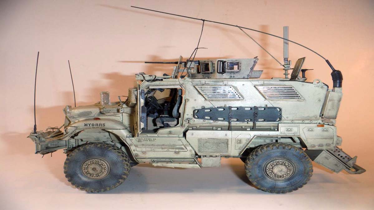
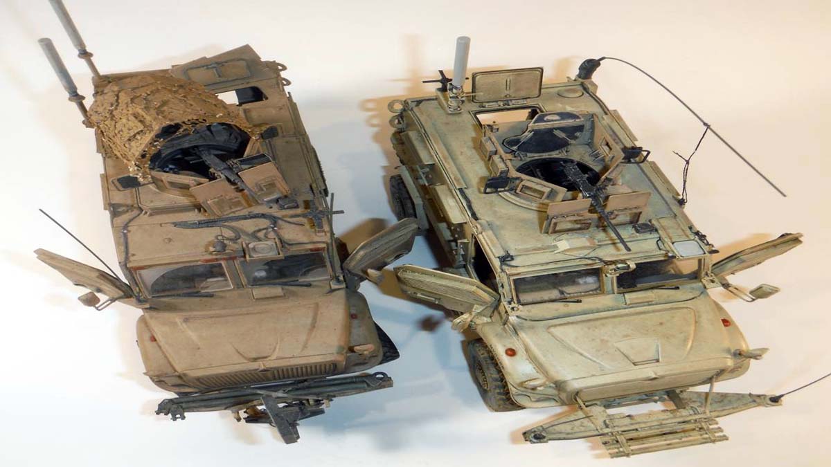
Once all closed up and with all the jumping around, there was not much left to do to the exterior. Technically because there are only four radios inside the Maxxpro, there are four antennas outside. The SATCOM X-wing antenna and long whip antenna went to the Harris set, and the two whip antennas in the front went to the SINCGARS set. Therefore, I left the two antenna brackets next to the windshield empty. Also, proper cables where run through the conduits on top to their proper location. All this is covered in my communications tutorial. The tow strap was made out of Tamiya tape. Clear parts where installed and masked. Along with the photo etch window grills, the entire model was painted with a mixture 10% Tamiya Desert Yellow and 90% Tamiya Flat White. After all the decals where placed and everything sealed with a clear flat, I carefully glued the window grills in place. The lower hull and wheels were dusted with Vallejo Pigments.
Conclusion
First and for most, if it doesnt matter to you that this is not a true Maxxpro DASH DXM as far as the interior is concerned, then go for the build. But, if you are, there will be a lot of scratch building involved to fix the interior. Remember that the drive axles are incorrect also and will need EXTENSIVE work to correct. As far as complexity and fit issues, the kit is better than some of Pandas other kits. Hopefully an aftermarket company will come out with an extensive correction kit.
SUMMARY
Pete Becerra reviews and builds the M1235A1 Maxxpro DASH DXM in 1/35th scale from Panda.
Our Thanks to Panda Hobby ! This item was provided by them for the purpose of having it reviewed on this KitMaker Network site. If you would like your kit, book, or product reviewed, please contact us.
About Pete Becerra (Epi) FROM: TEXAS, UNITED STATES
I am 48 years of age. I have been modeling since I was around 8 years old. As you can see from my signature, I am retired from the US Army and Texas Army National Guard. I served 6 years in active duty from 1989 to 1995 and in 1998 I joined the Texas Army National Guard and been serving up unt...
Hi Pete - thanks for the comprehensive review and the tutorial. Both are very helpful. As for the axles, Ive built a few of the Panda MATVs, and while a diiferent unit, the independent suspension modules are characteristically similar to the Maxxpro, but substantially harder to build. While this version doesnt include the differentials, the suspension goes together pretty well.
I think the MATV suspension units are so hard to build because the parts dont fit that well - maybe Panda sought a more builder friendly version for the Dash - who knows? Maybe they could have kept the straight axle element (which goes together well) and included some add-on shells to represent the diffs...?
Thanks again for the clear and helpful review,
Nick
Nice review and built.
I've just began this kit and there some curious mistakes. Some parts don't have pins while there are holes for their placement.(??)
One part well drawn on the instructions, is poorly molded with a missing extremity(F56) (???)
Curious choice for the gunner platform position (vertical). It is in one part with the support so rebuilt it for a figure placement.
High level of details, a lot of cables on the roof, thank you for the pictures ! Top views are very usefull to see the wiring.
The front lifting eye on the right side need to be drilled. I don't understand why Panda has made it blocked.
You can also scratchbuild running board extensions on both sides.


Comments