introduction
The M4 Sherman was the backbone of American tank production in WW2, with design work started almost as soon as the bombs stopped dropping at Pearl Harbour. It evolved rapidly over the next few years based on intensive combat use, with the final flowering being the M4A3E8 as depicted in this kit. Highlights of this last version were the Ford GAA engine, T23-style turret with 76mm M1A2 gun, and of course the Horizontal Volute Sprung Suspension (HVSS) that gave it a much bigger appearance than its predecessors.
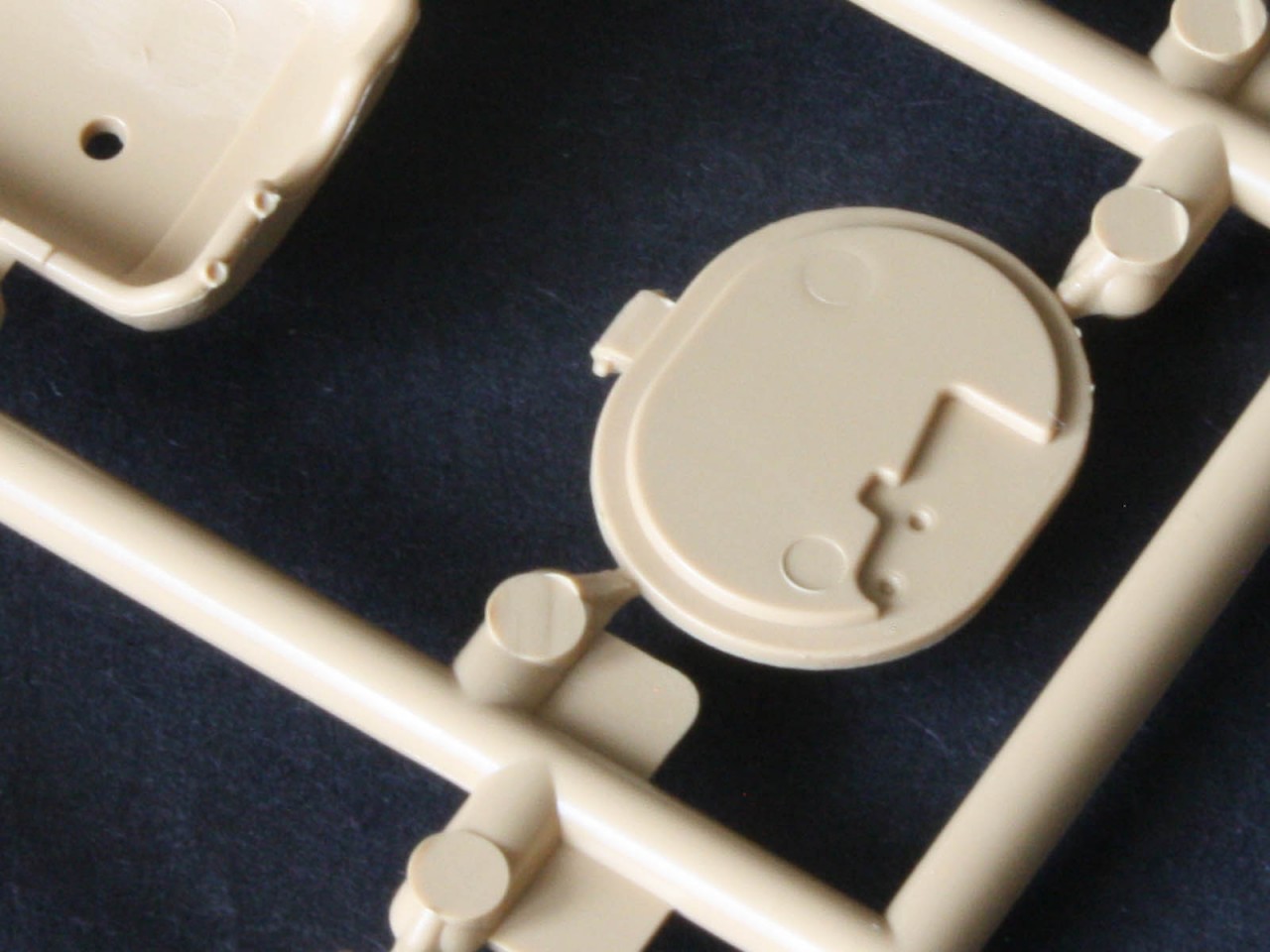
Even within this last type there were detail evolutions. The loaders hatch changed from the split circular early-Sherman hatch to the oval one-piece design, lift rings on the front glacis moved towards the outer edge, and the earlier sheet-metal scoop exhaust deflector was replaced by a two-piece armoured deflector that could better protect the radiators up under the hull overhang. And the tracks changed from T66 single-link steel ones to T80 steel-chevron and T84 rubber-chevron types that looked like earlier Sherman tracks made wider. Most combat photos Ive seen show the T66 track, but there are a few out there with the T80 track as included in this kit. According to what appears in the
Son of Sherman book, the
Shaddock website, and Steve Zalogas
Armored Attack 1944 and
Armored Victory 1945 the E8 suspension makes its debut in Europe in January 1945, along with the oval loaders hatch, wider lift rings, and muzzle brake, but the armoured deflectors dont arrive until March 45 at the earliest, and while the mantlet canvas cover fittings start to appear on turrets around this time, the actual canvas seems to have missed most of the fighting. Post-war there was an upgrade programme that saw older tanks retro-fitted with the deflectors, the canvas, and two other features that are associated with the Korean war an infantry phone box on the rear and an armoured first-aid box on the hull side.
The M4A3E8 has been kitted in 1:35 scale by a number of companies, including Tamiya, Academy, and Tasca (now Asuka see my
review). Now Rye Field Models (RFM) is moving in to the Sherman neighbourhood with this as their opening gambit, and readers will note how similar this kit is to the Asuka version in terms of construction and the details offered. But dont think for a moment that this is a clone or re-box this is definitely a whole new kit using new tooling! It represents the very end of M4A3E8 production. A number of details suggest they have plans to do more versions.
Note that our very own Donald Wolozanski (callsign OldWarloke) started a
build log on this kit, and his blog is well worth a look. This review is based on a sample build of the kits more tricky elements, because with over a thousand parts for the tracks alone it will be weeks if not months before I finish it
contents
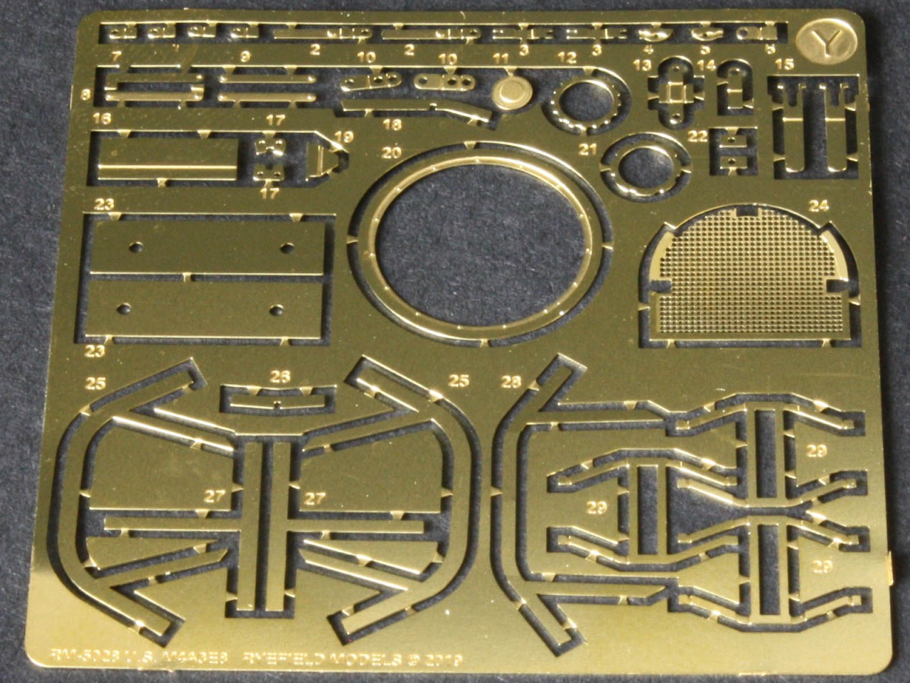
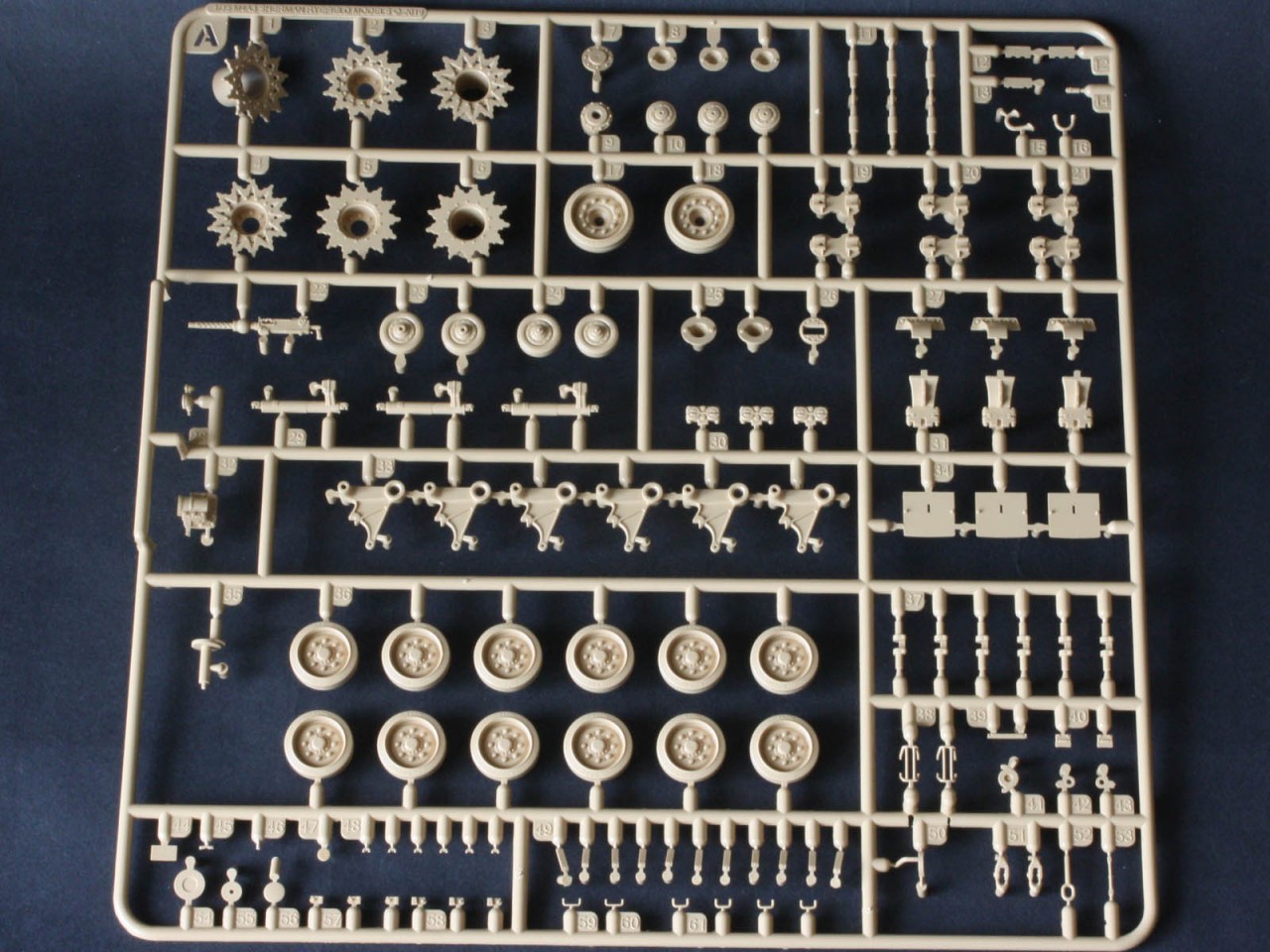
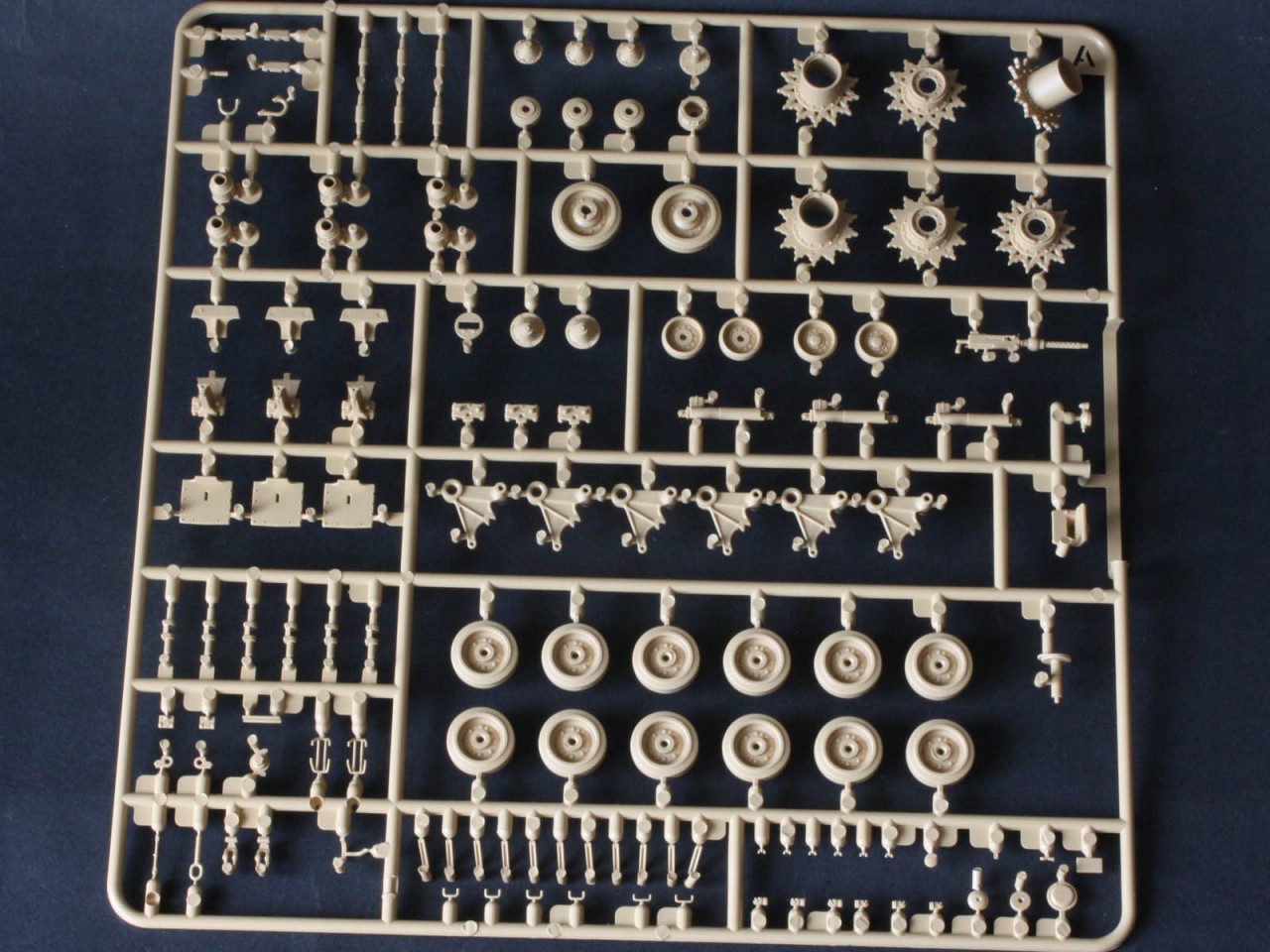
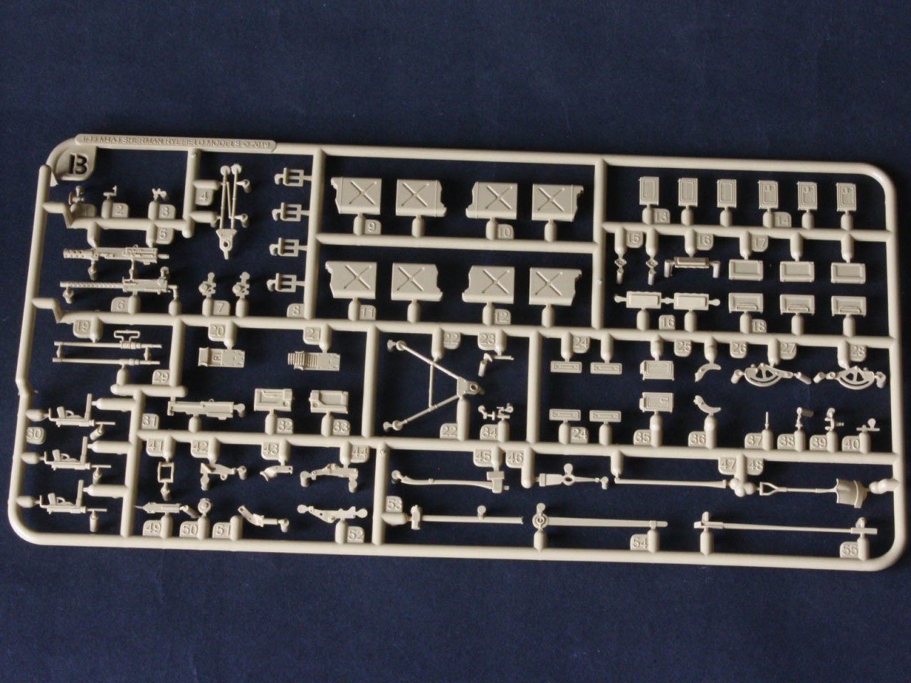
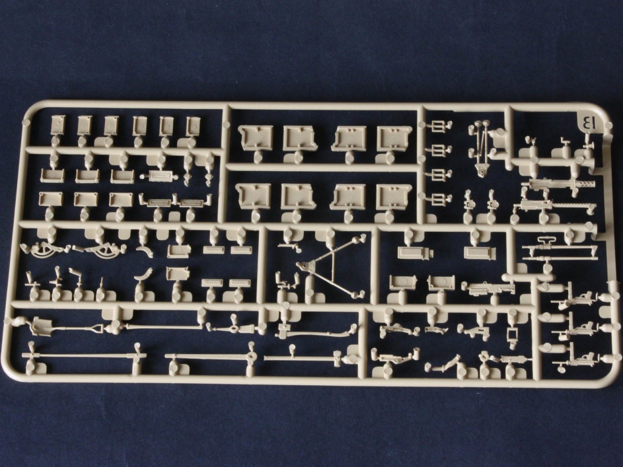
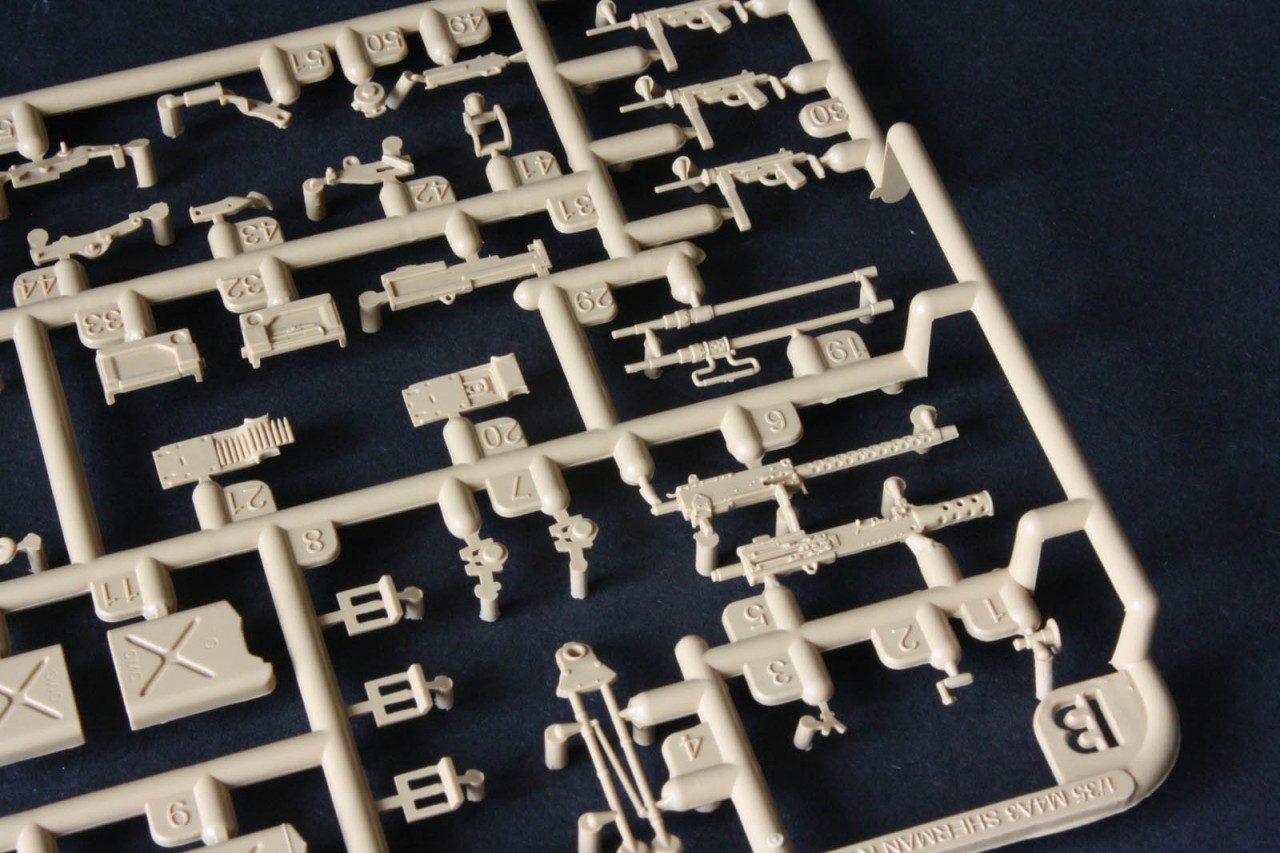
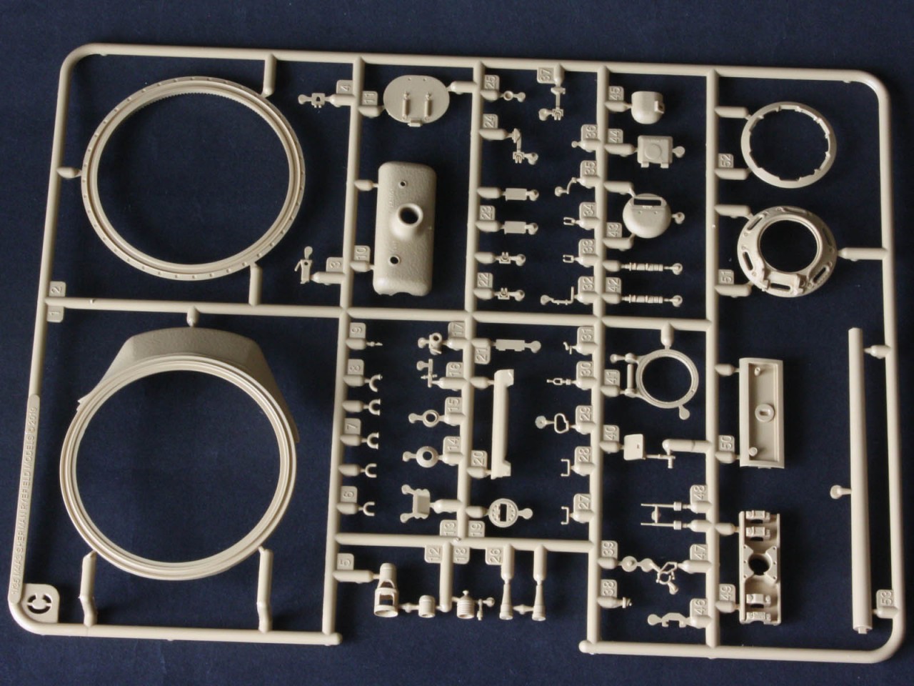
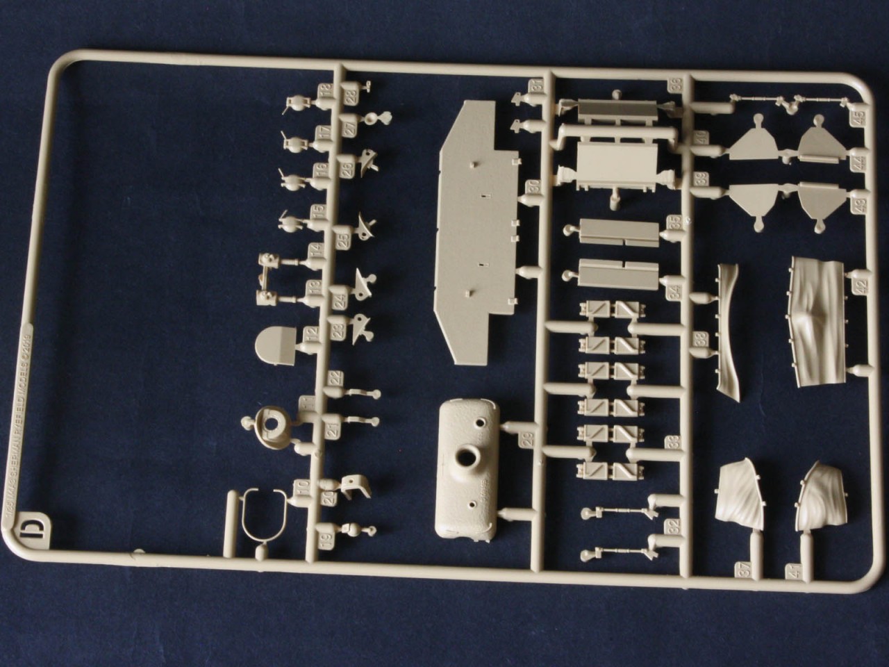
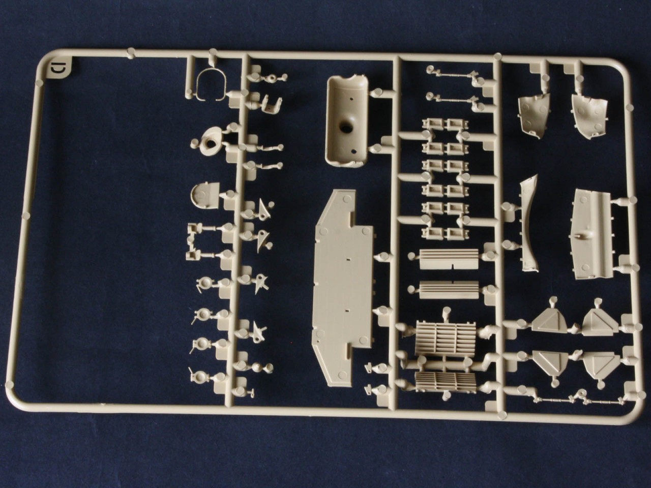
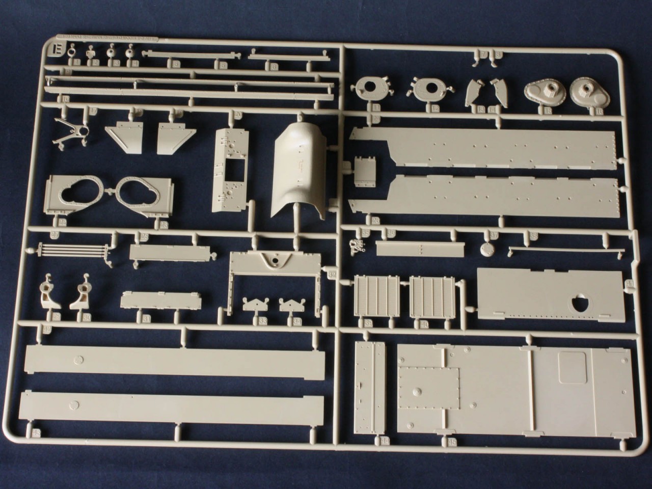
Packed within the standard box are the upper hull, turret upper half, and ten tan sprues holding 1506 parts! Then theres the clear sprue with 17 parts, a photo-etch fret with 44 parts, four polycaps, and a string. Thats a whopping 1970 parts for one Sherman. Moulding is crisp, and while there is a little seam flash on some sprues compared to the Asuka kit, clean-up should be easy. Bear in mind that the tracks account for the lions share of the count (1012 parts!), so the tank itself is less daunting. Each sprue type comes in its own clear sleeve to avoid damage in the box, as do the hull and turret.
So what do we get?
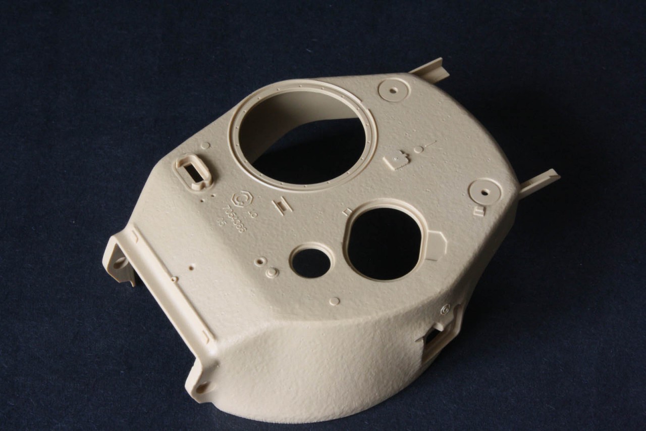
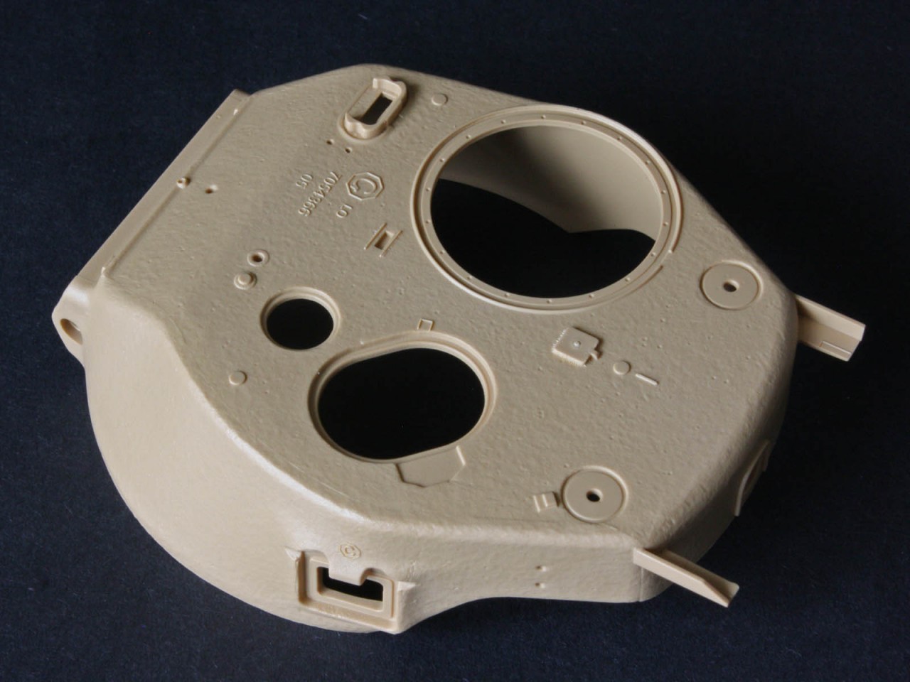
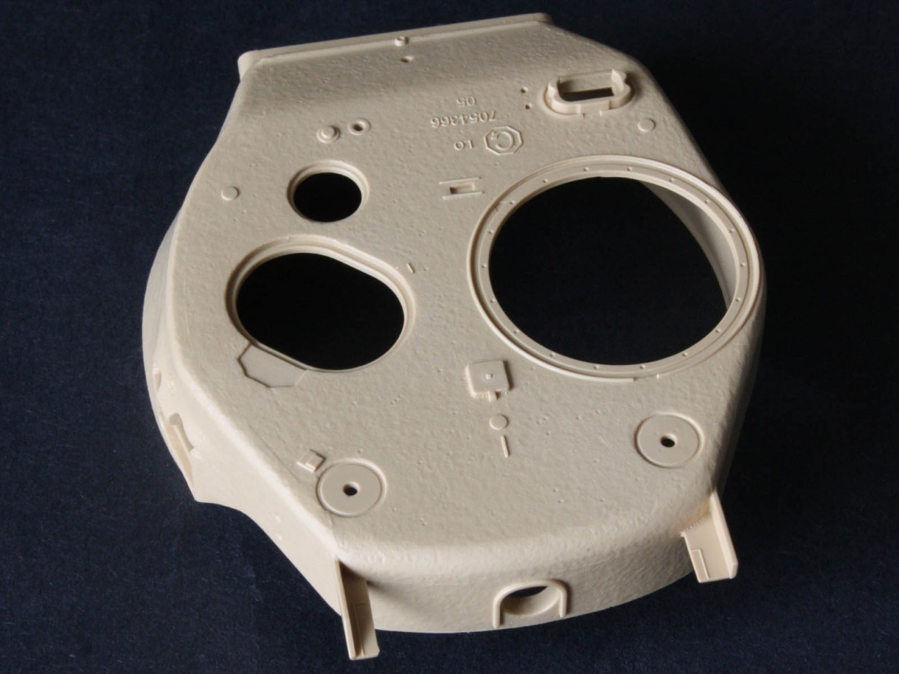
Turret
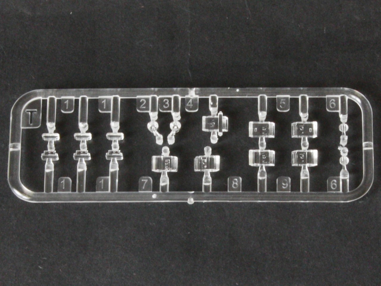
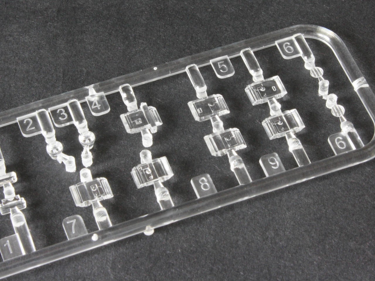
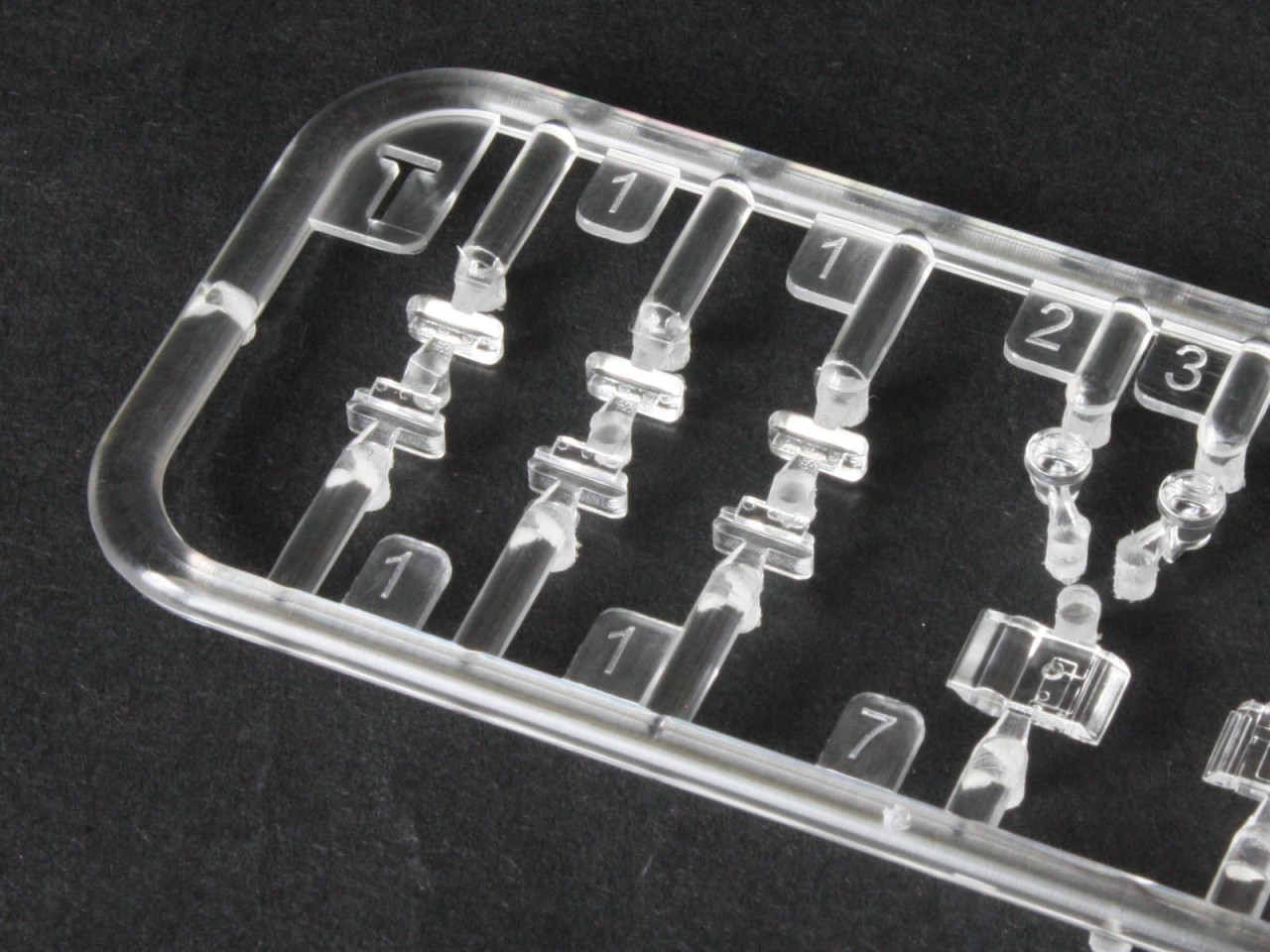
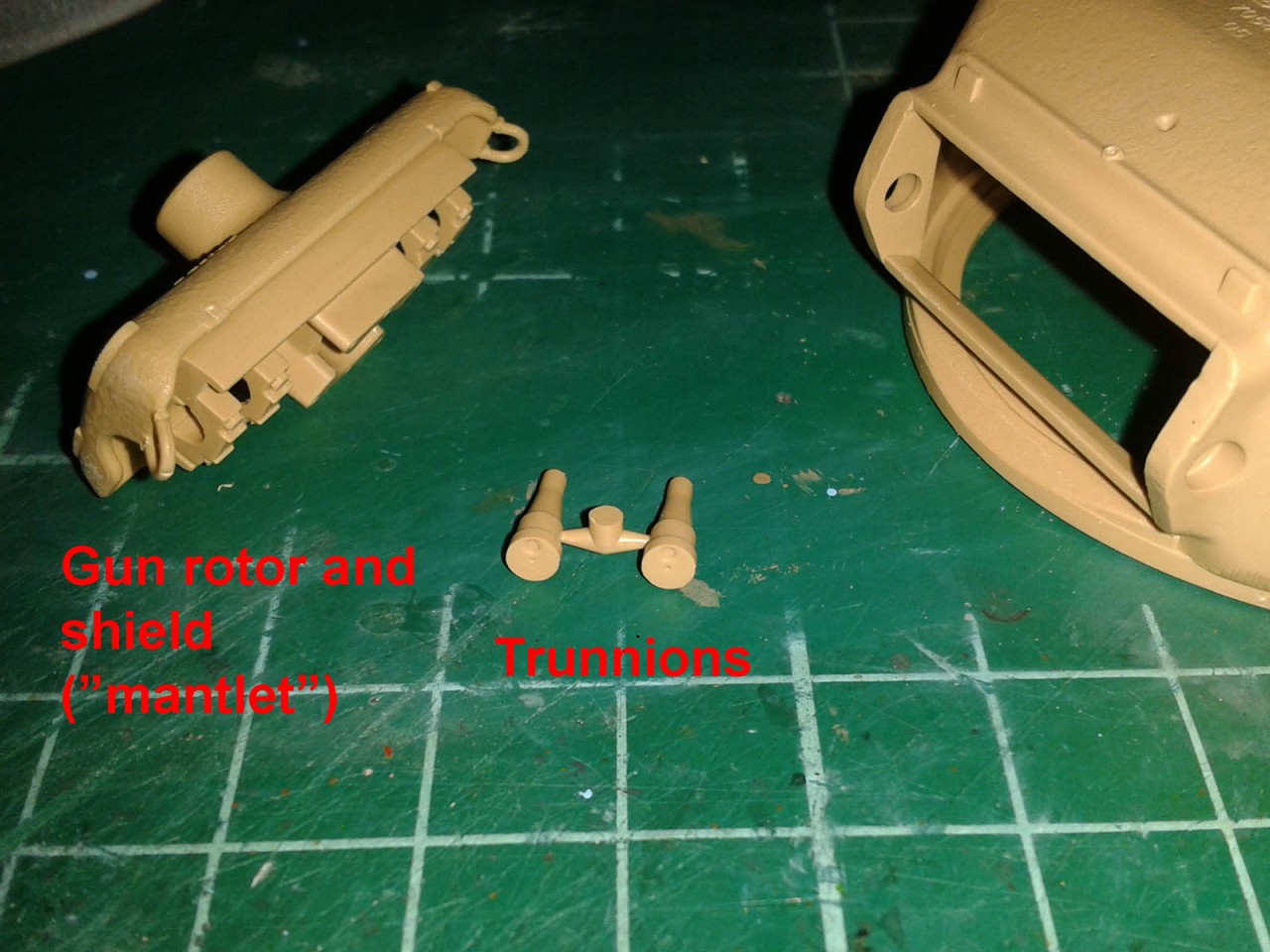
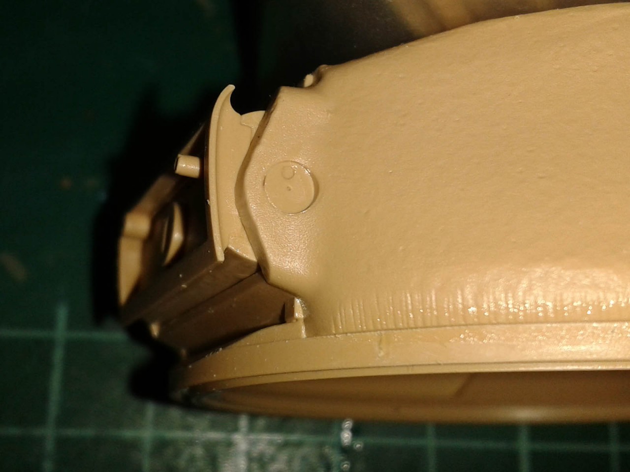
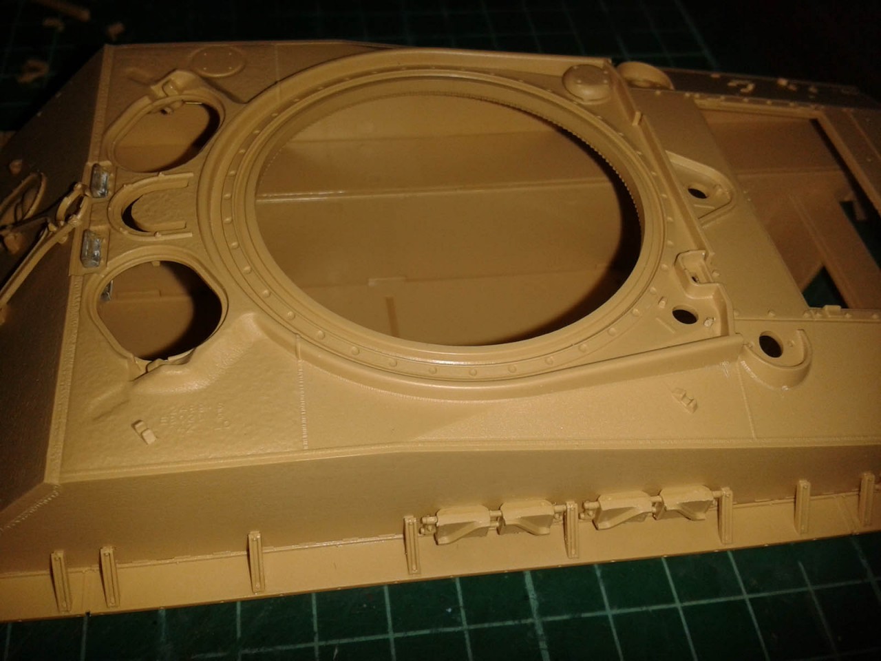
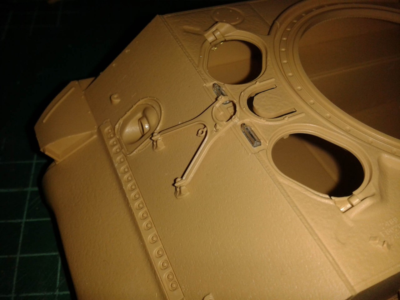
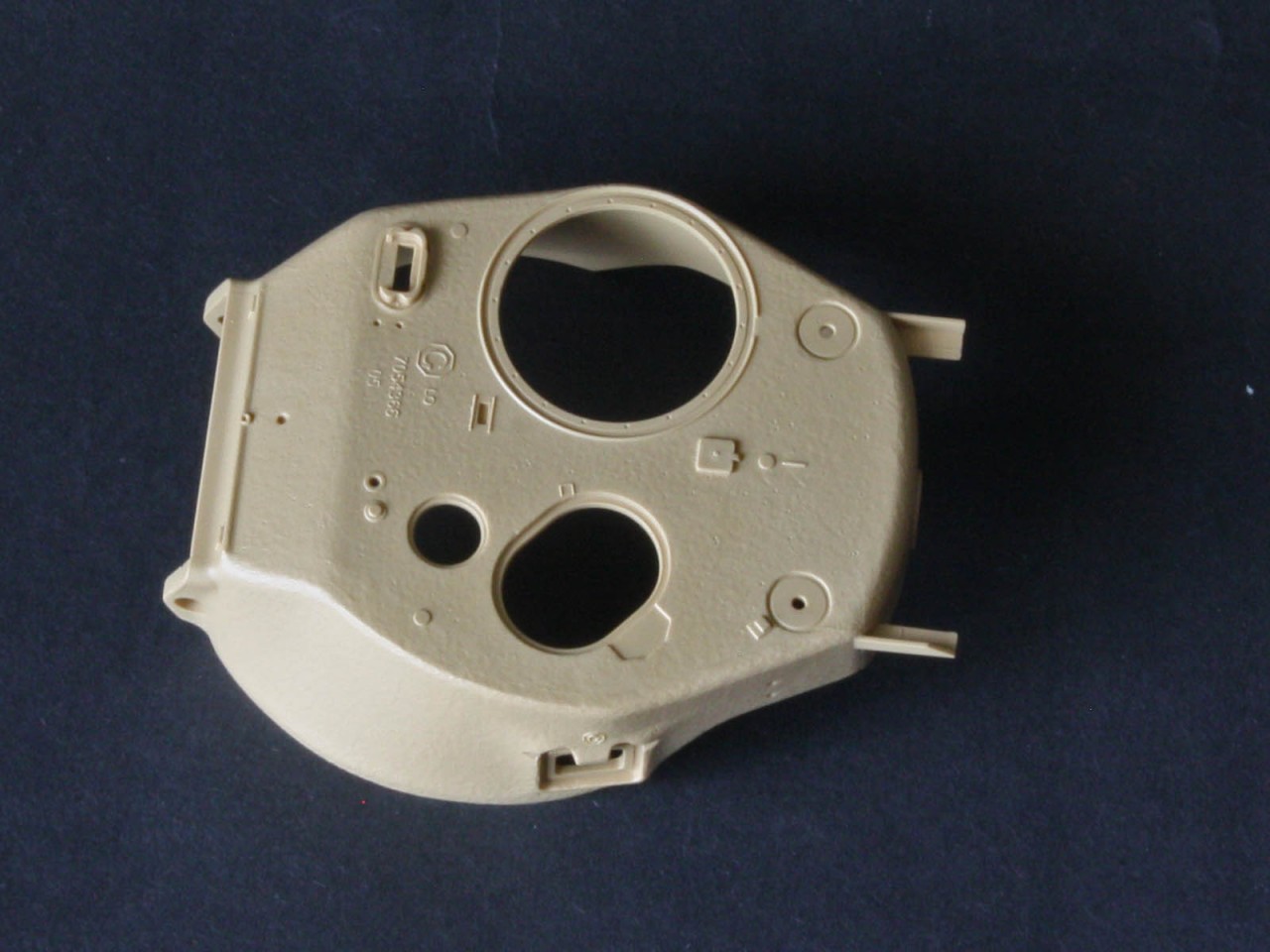
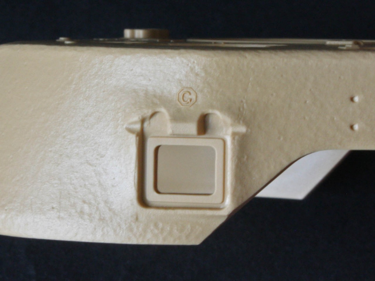
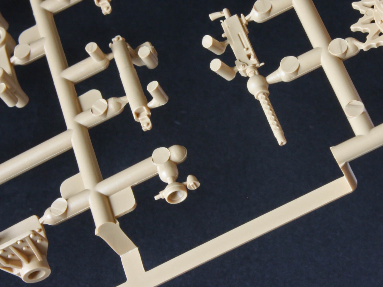
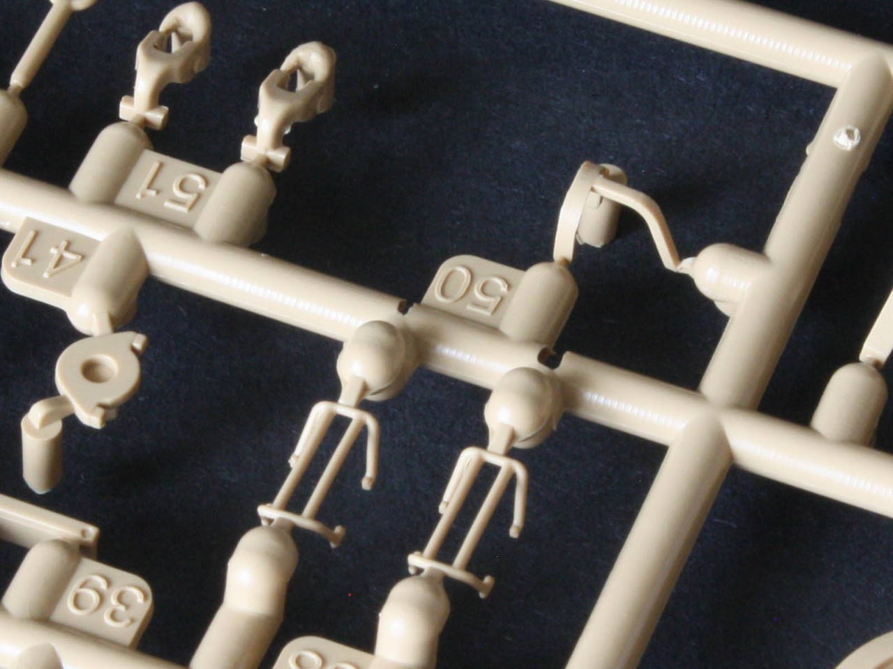
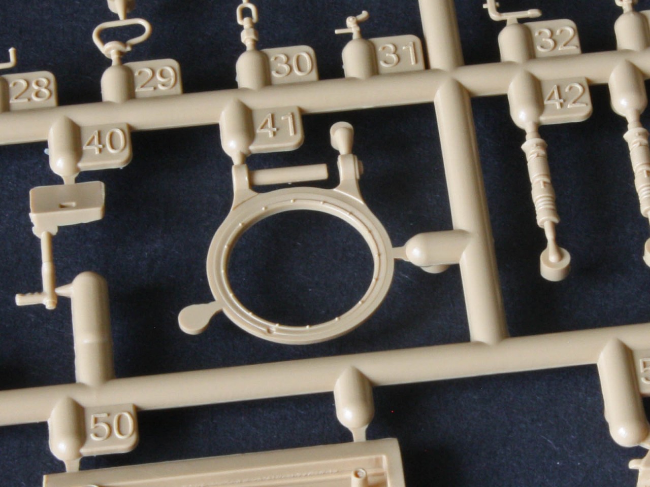
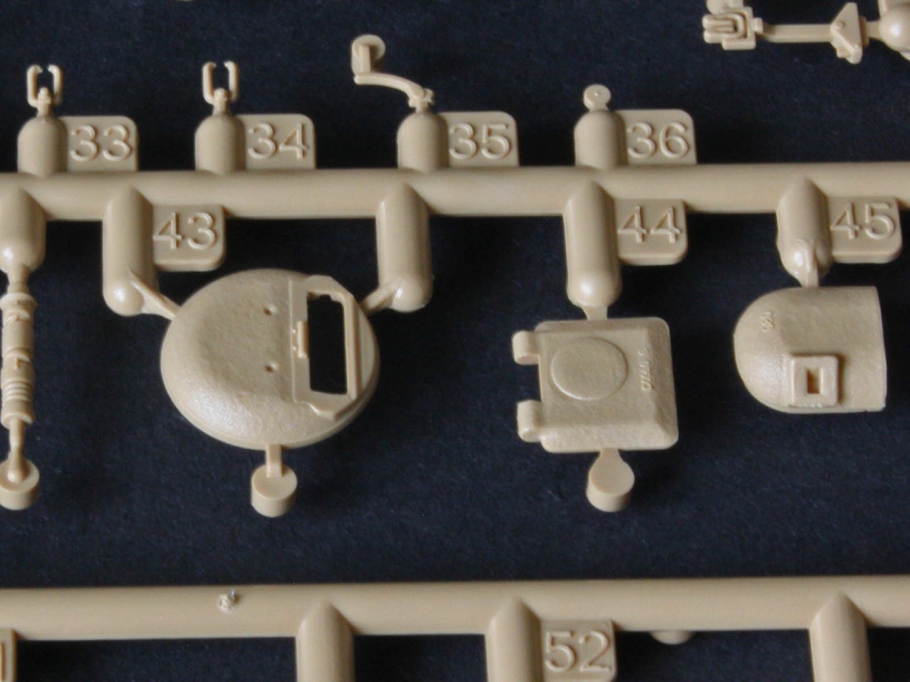
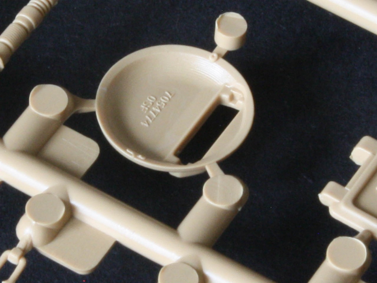
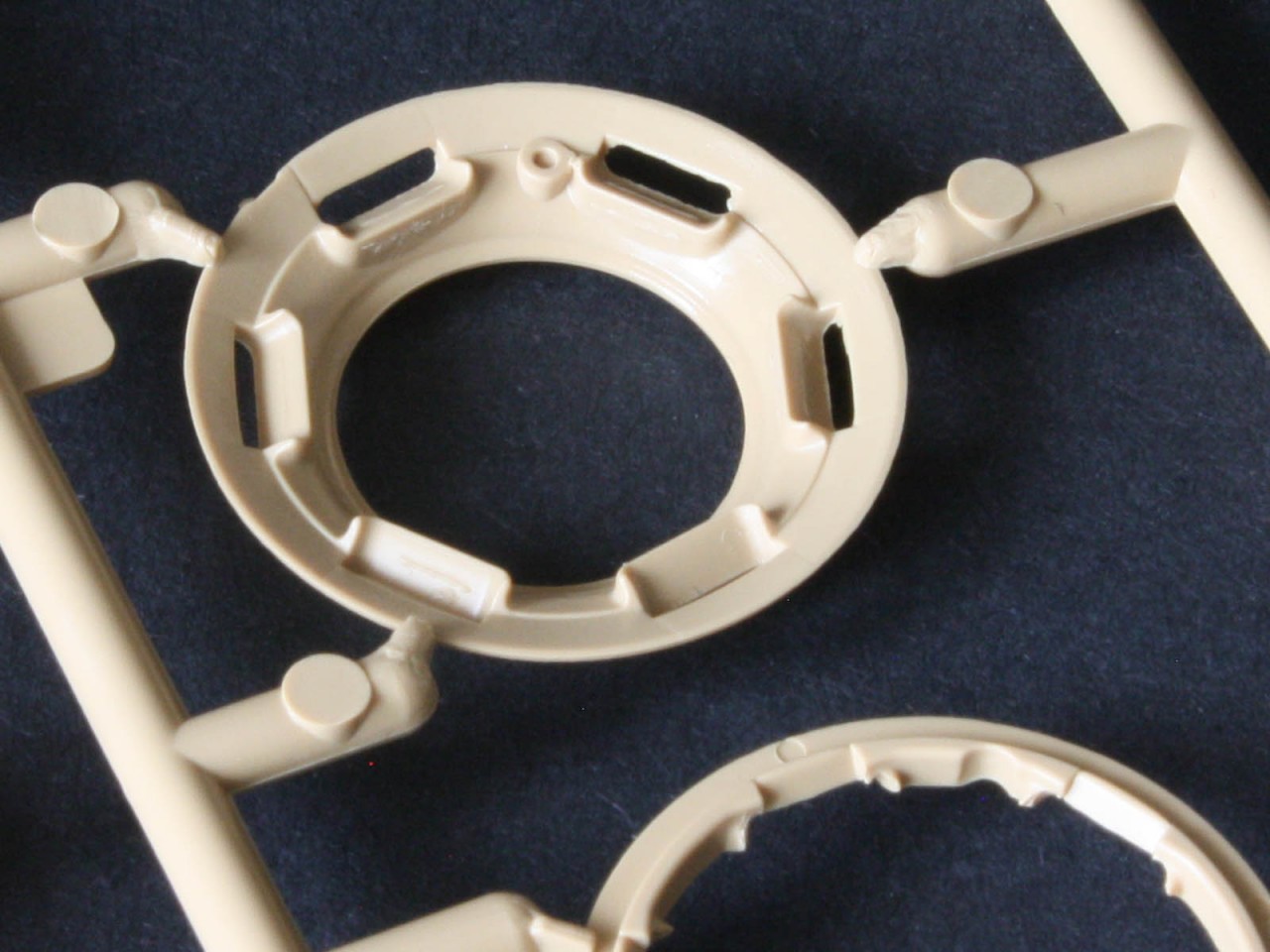
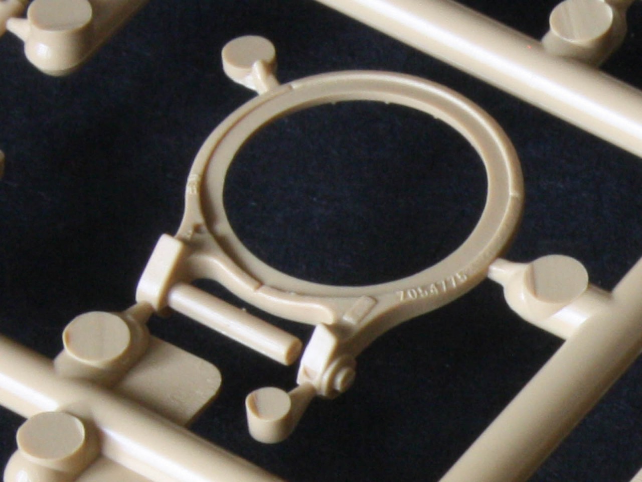
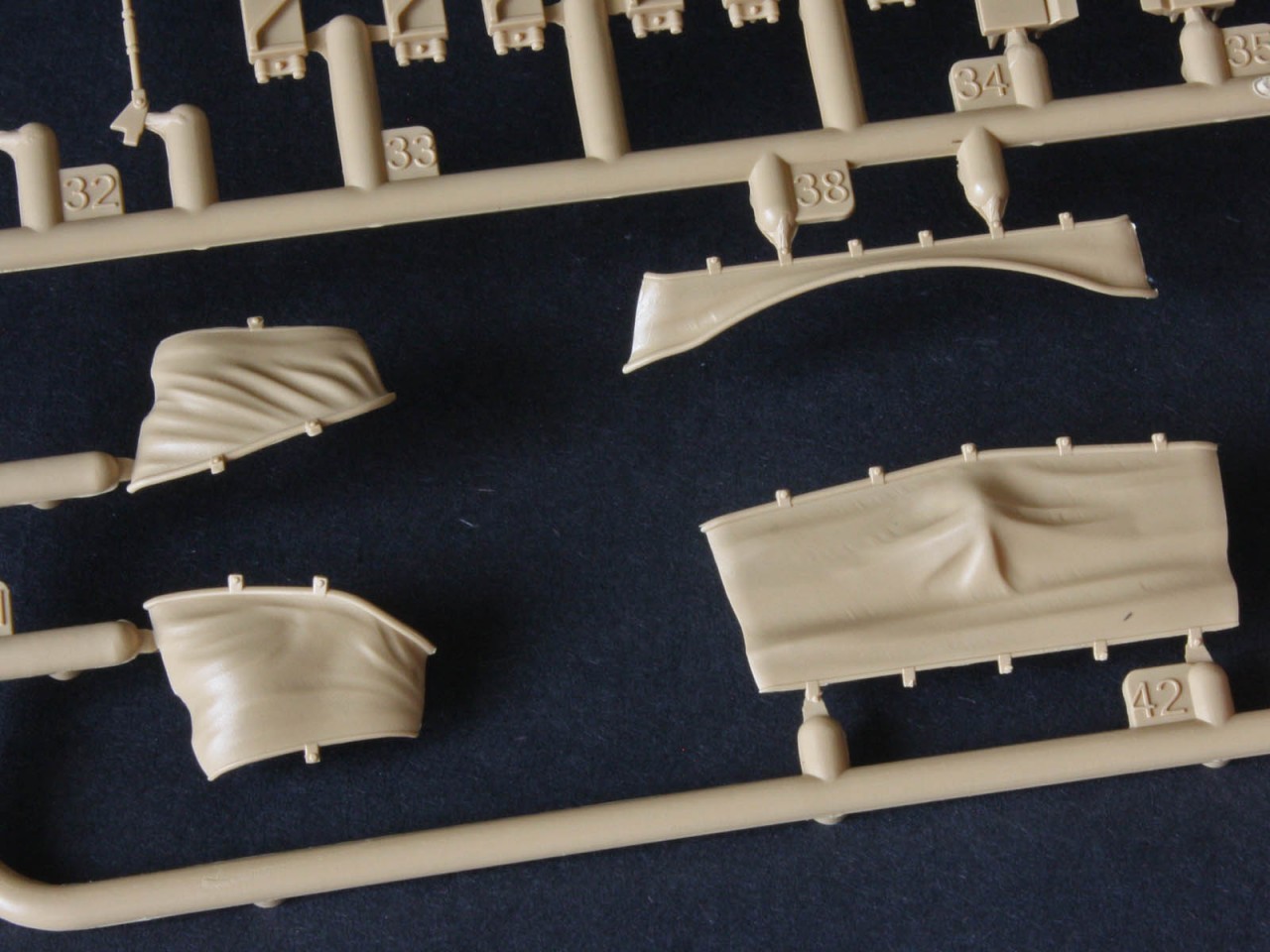
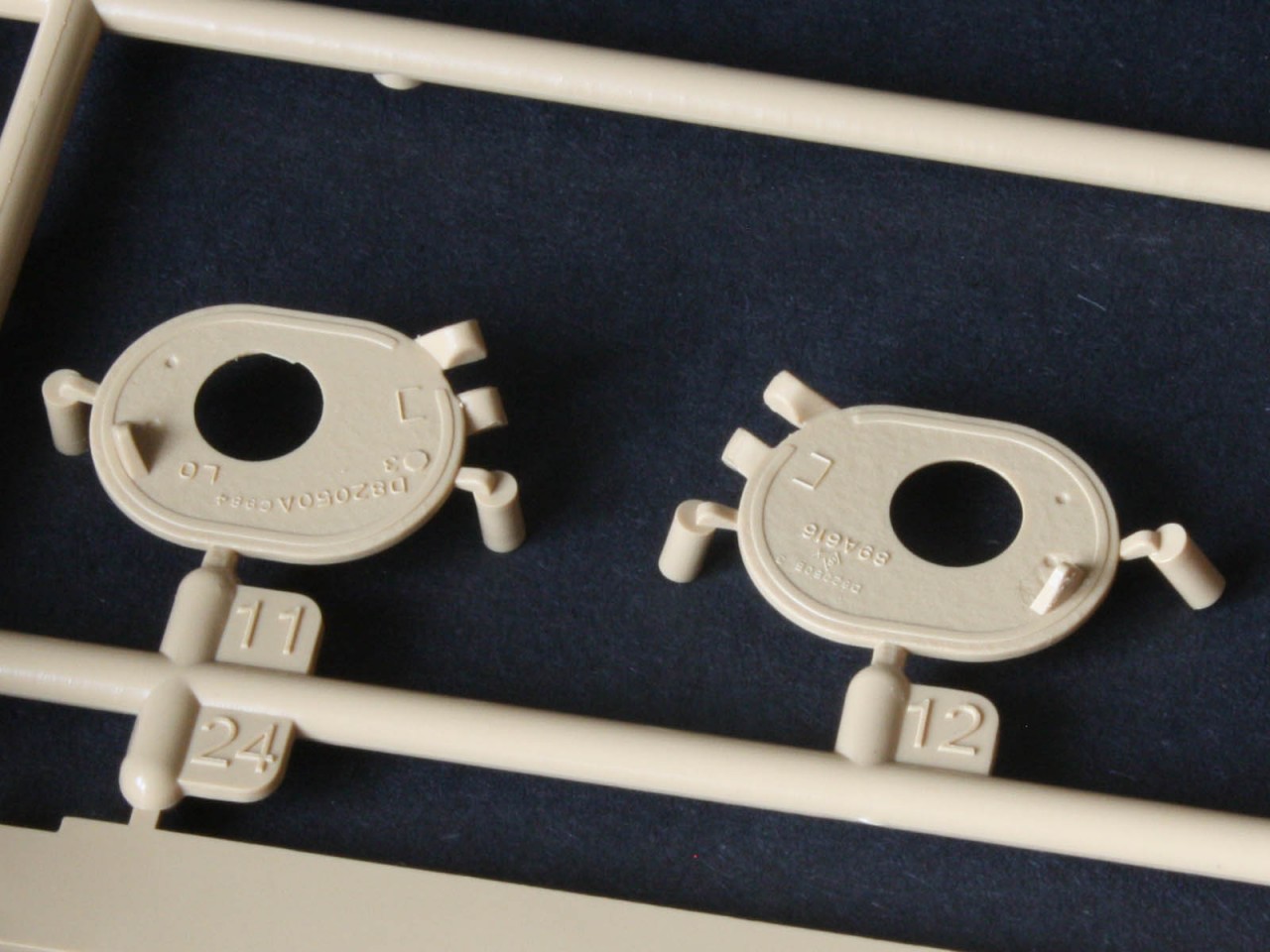
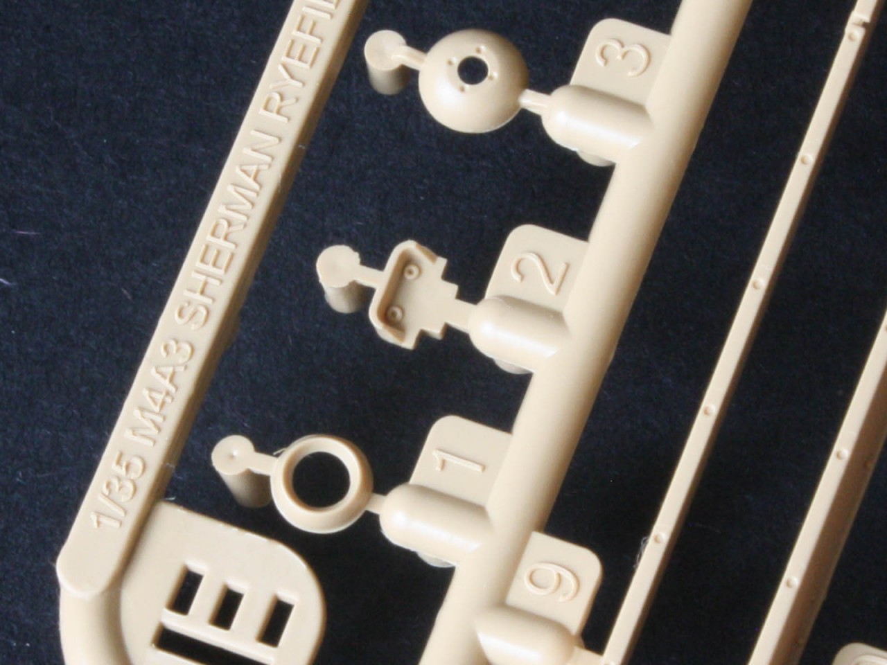
Starting with the turret we get quite a delightful amount of detail, including casting marks on most of the parts shell, mantlet, ventilator dome, cupola, cupola hatch ring, and the hatches themselves. Some of these really need a magnifying glass to see! (The ones Ive checked so far seem to be correct well done RFM for outshining the competition.) There are two different mantlet shields with or without the L-shaped corner brackets for the canvas dust cover, which comes as a four-piece assembly. The gun rotor has details on the inside face, where they cannot be seen unless the gun has been removed for maintenance this includes a large round hole for the barrel as it enters the turret space, but the outside face has only a slot for a tab locating the end of the kit barrel, suggesting a separate gun mount interior was planned but not executed. The hatches come with underside detail, allowing them to be posed open. Sadly the loaders hatch has the two very obvious springs moulded on so they have a very blocky appearance but posing the hatch open will hide them! The commanders hatch is a true work of art, with the central dome being able to rotate if glued to the PE bolt ring that effectively traps the hatch frame, but I seriously doubt my ability to glue it that precisely without locking it up. The cupola vision blocks are separate clear parts that get trapped into the cupola by an inner ring that I suspect will allow me to paint the cupola before adding them. We get a choice of antenna mounts two MP48s (the chunky sprung bases, although RFM forgot to mould the spring detail shown in the instructions we just get a cylindrical area where the spring should be), two AB15s (thin rubber-tubed bases with insulators at the bottom, introduced near the end of WW2 and common by the Korean War five years later), and a plug for the second mount behind the loaders hatch. Most tanks would have the MP48 behind the cupola, but command tanks might have the second base fitted either the MP48 (at a pinch it should be an MP37 or MP57) or the AB15 for the command-net second radio. There is a great article on these antenna systems that can be found
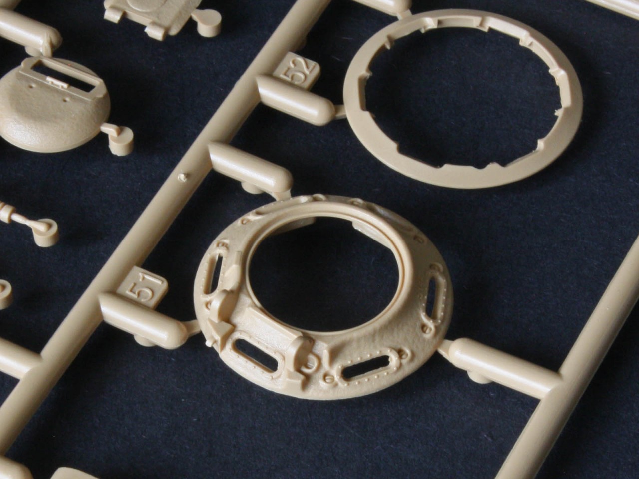
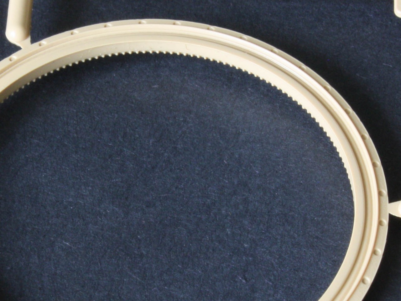
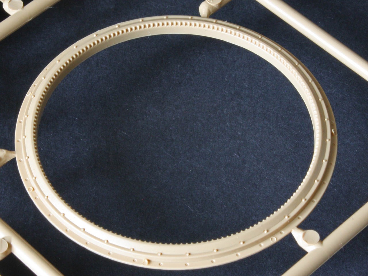
here. There are some tiny fragments of PE that are necessary for the turret, such as the bracket for the commanders hatch lock, and the padlock hasp on the loaders hatch. Round the back, the vent aperture is a round hole that gets covered by the vent dome ideal if RFM plans to use some of the CAD to offer an early M4A1(76)W Operation Cobra tank in future. The main gun has a solid tube with separate muzzle brake that has a front ring with the four bore-sighting lugs missing on everyone else kits bravo! But sadly there is absolutely no interior detail to see through the hatches no breech, or recoil mechanism. However, there is a surprisingly detailed turret ring complete with gear teeth, and the obligatory ring of bolt holes below the cupola (as piloted by Tasca a decade ago) as well as the aforementioned interior-face details on the back of the gun rotor suggesting some indecision about whether to add an interior.
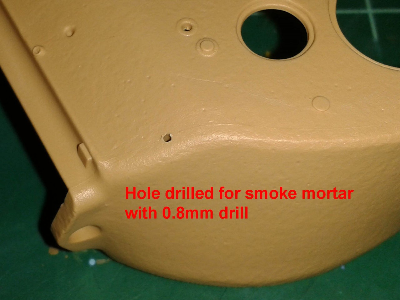
The turret represents a fairly late type, with no smoke mortar tube at the front left of the roof. I believe this was deleted sometime after WW2 with existing tubes plugged and welded, so its absence goes against the WW2 markings. However, the missing tube is in the kit as part C38, and there is a blind hole in the turret shell to be drilled out for it the instructions just fail to mention it at all. The other omission is the mounting-pad hardware on the turret and mantlet for the dust cover if building the tank without the canvas. These canvas covers were to enter the spring 45 production, but for some reason while the hardware was on tanks issued in early 1945 the cover itself only appeared in the last two months of the war. Even then it was a very rare addition seen in few photos, so a tank of this configuration is far more likely to have a bare mantlet with mounting hardware on both mantlet and turret face rather than a completely bare shield or the full canvas. Academy solved this in its
M4A3 kit by having the mounting pads as shave-off parts on the sprue for the modeller to add, but they are fairly easy to make from Evergreen strip and a drill.
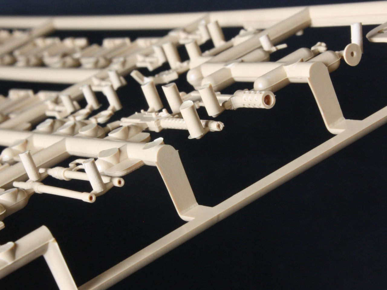
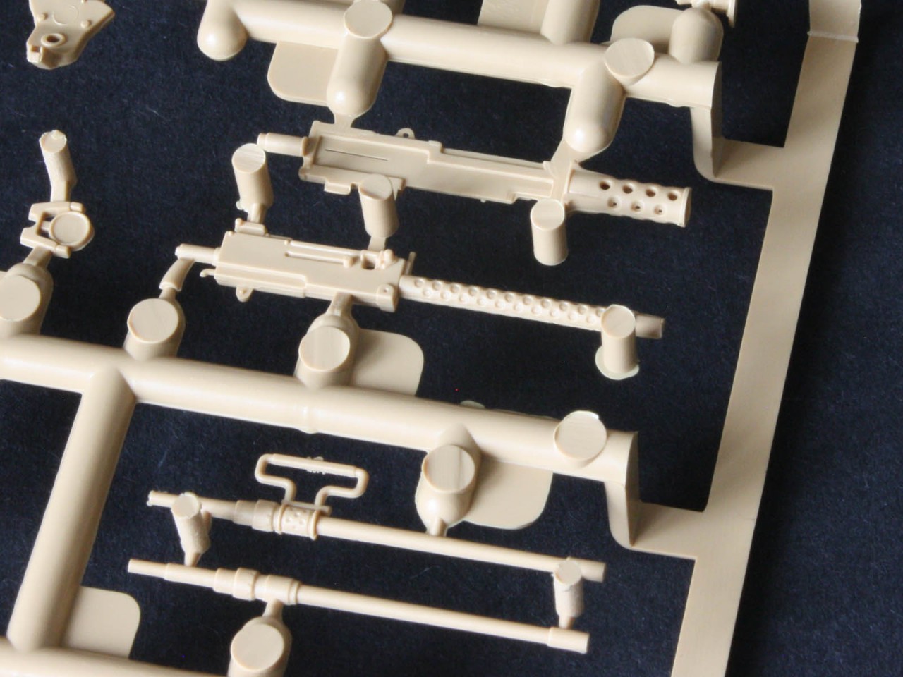
The .50cal machinegun is a beauty! Like the .30cal hull MG it has a slide-moulded opening, and the vented sleeve on the receiver has decent holes. The MG is on a par with the excellent Tasca/Asuka guns.
Hull
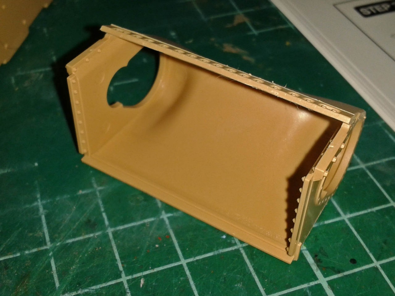
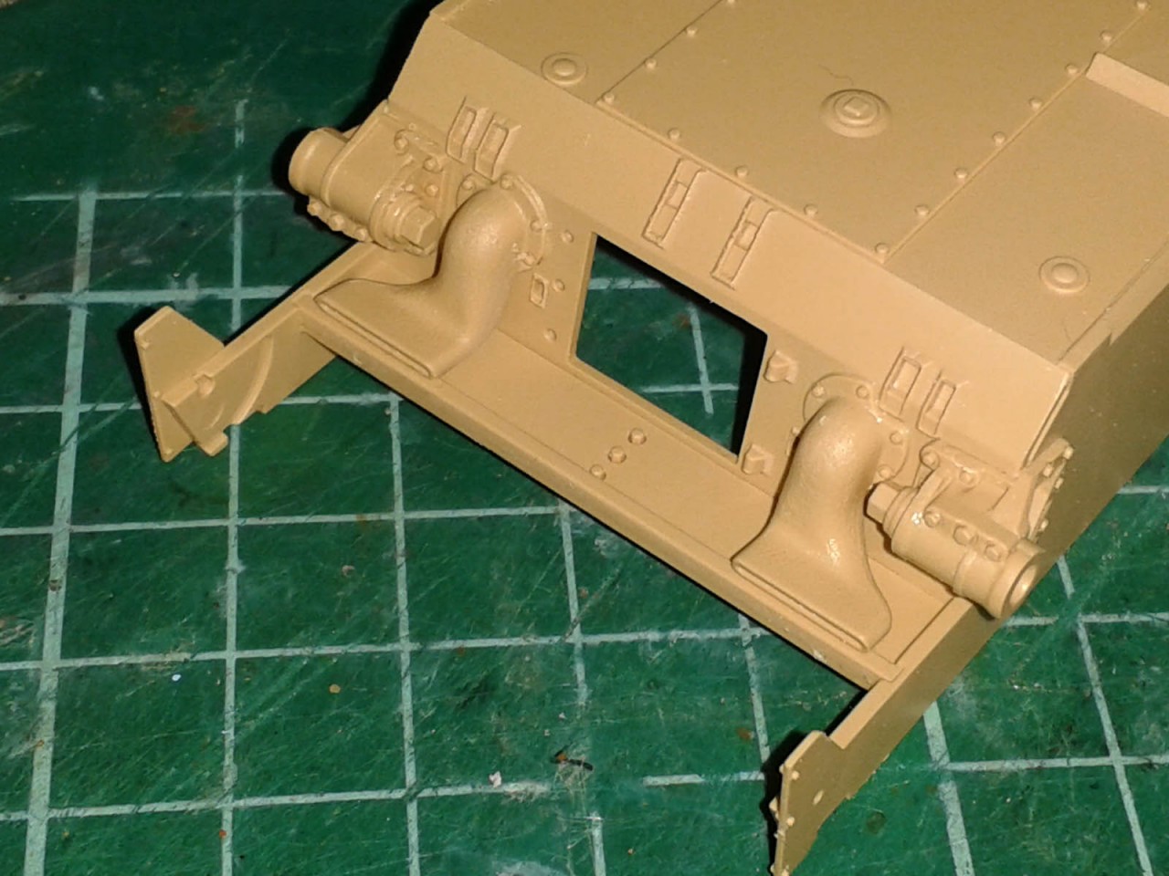
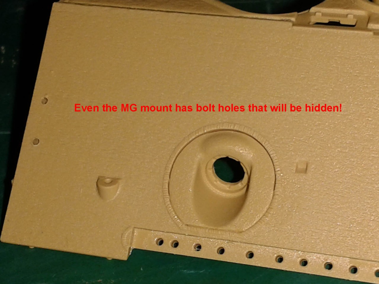
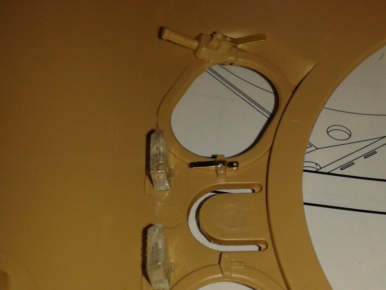
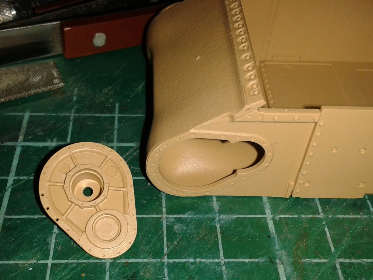
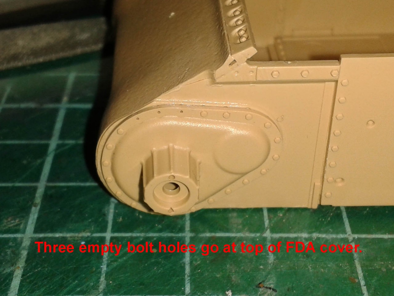
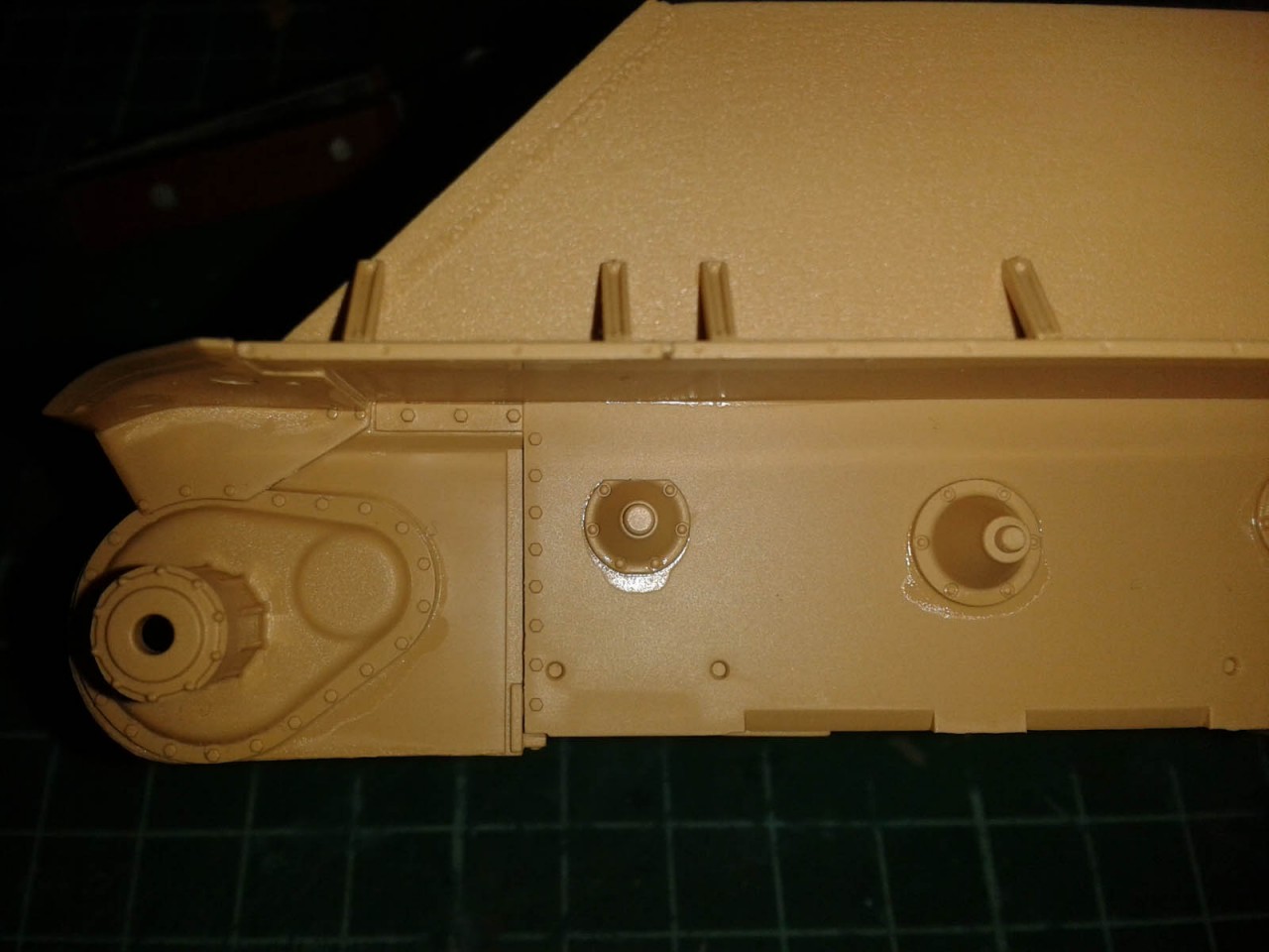
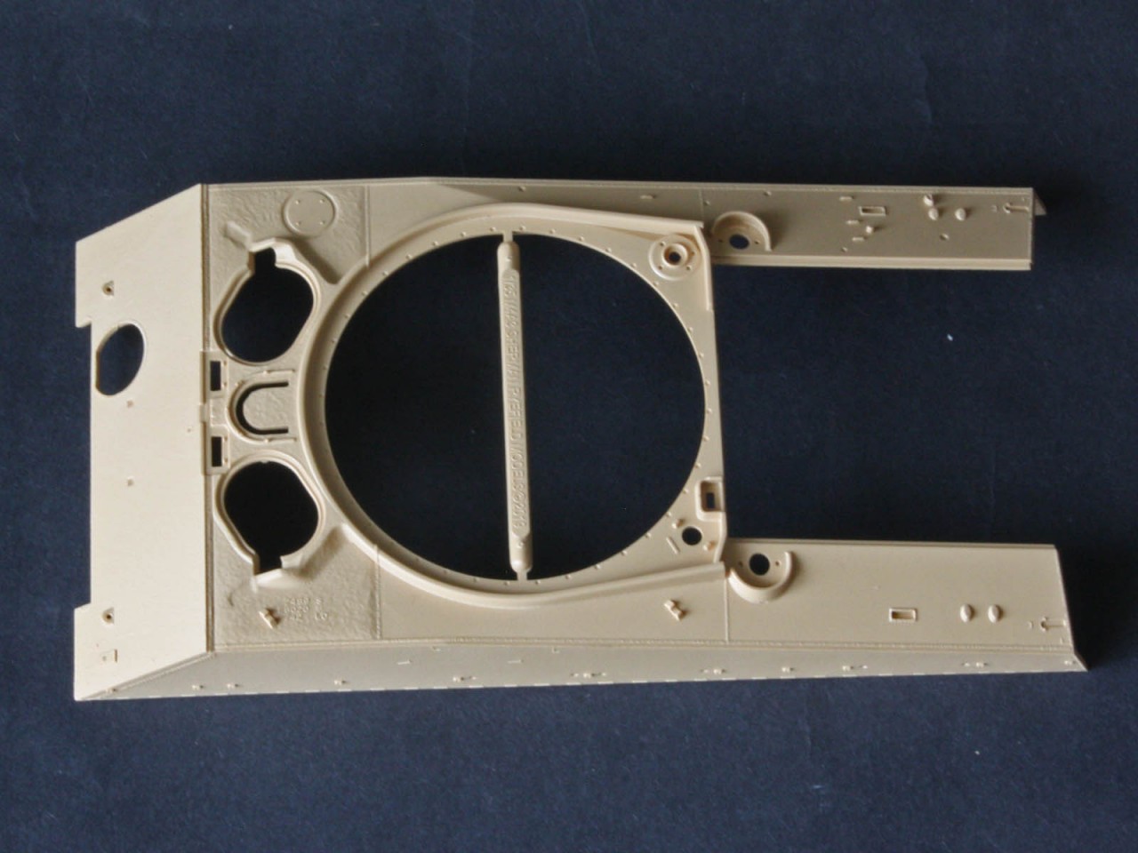
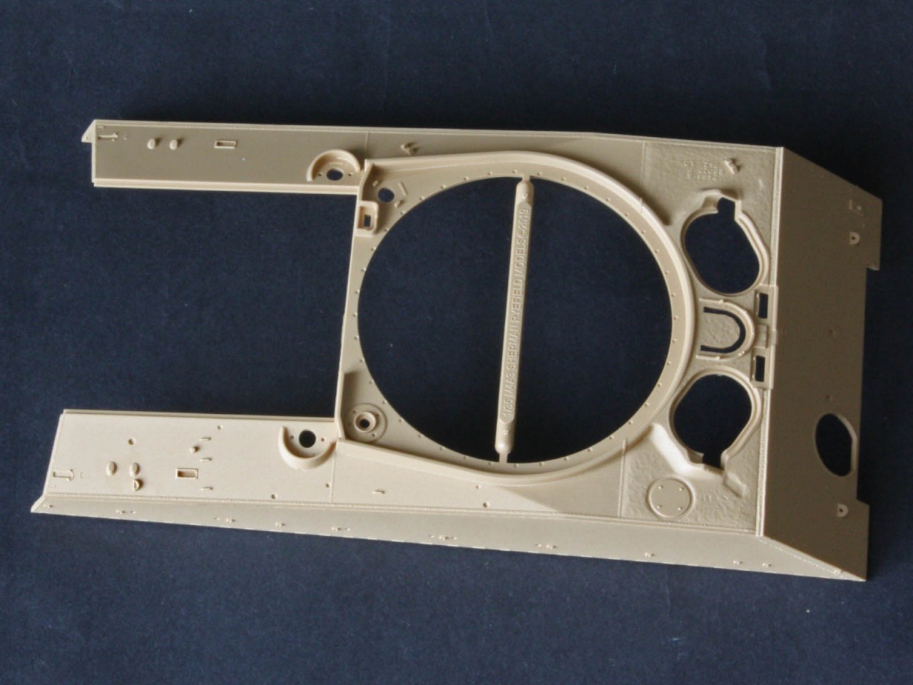
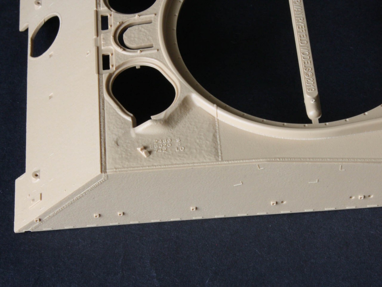
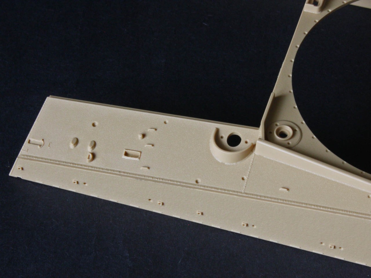
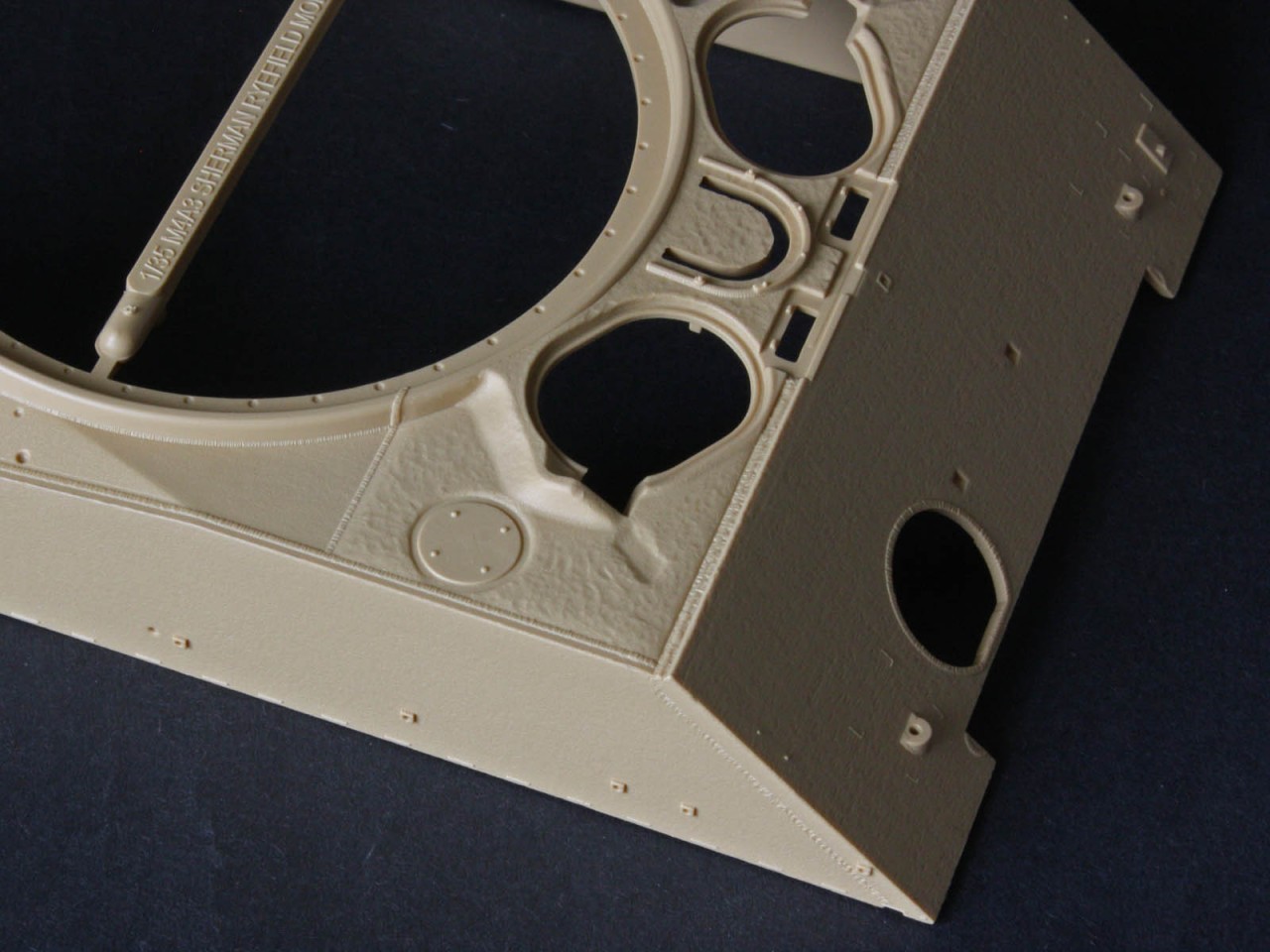
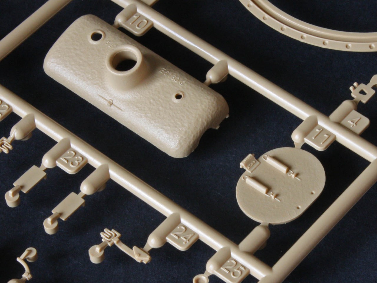
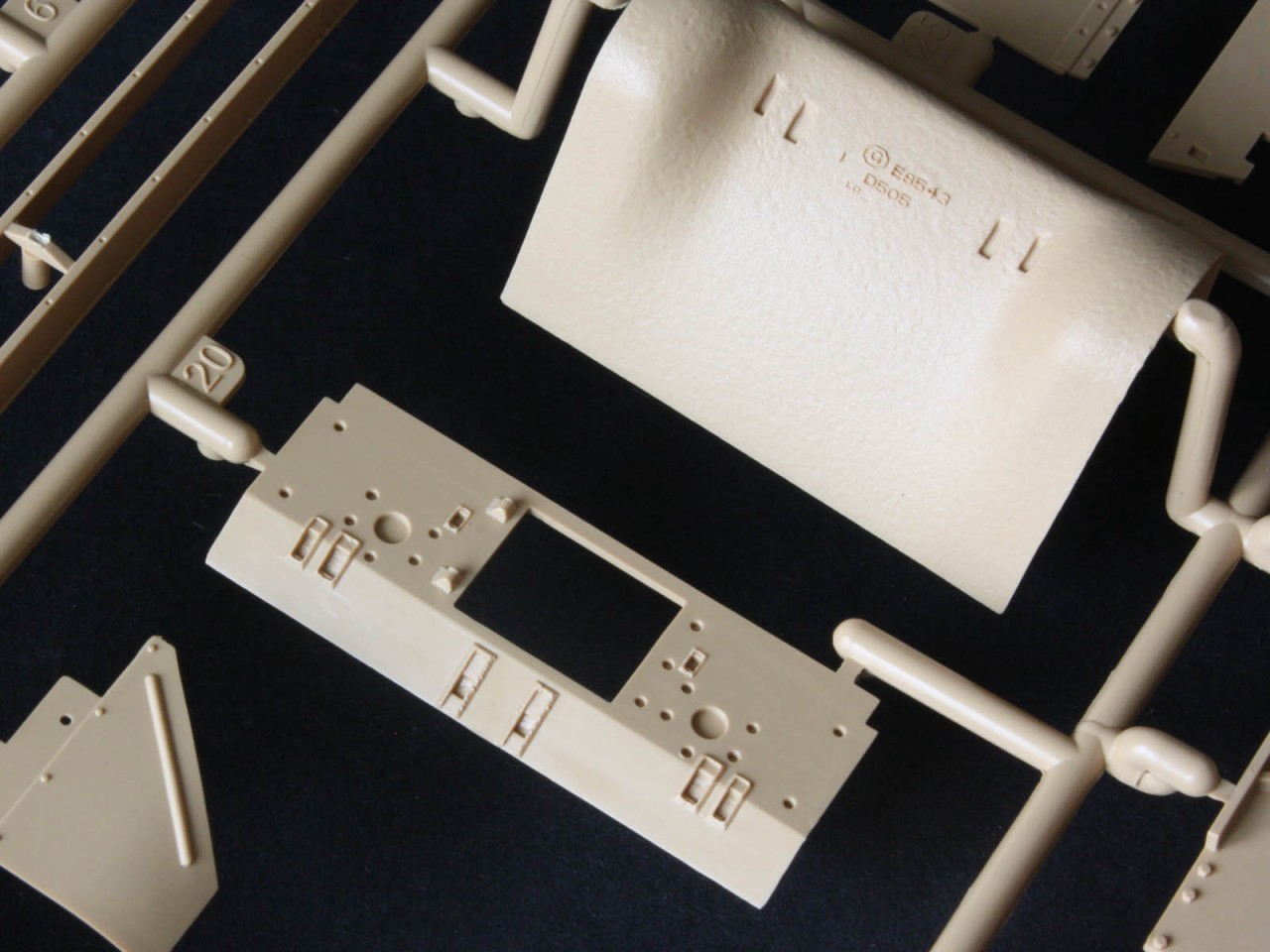
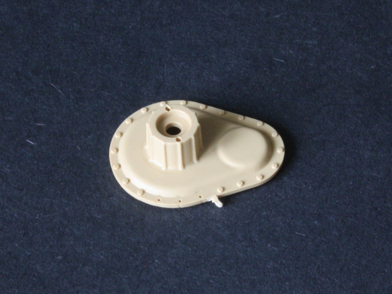
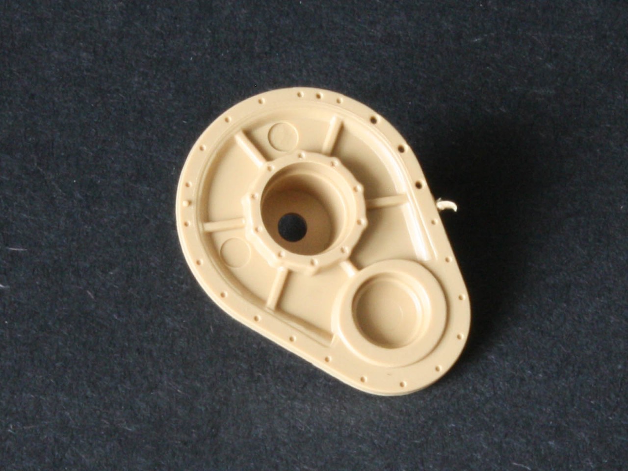
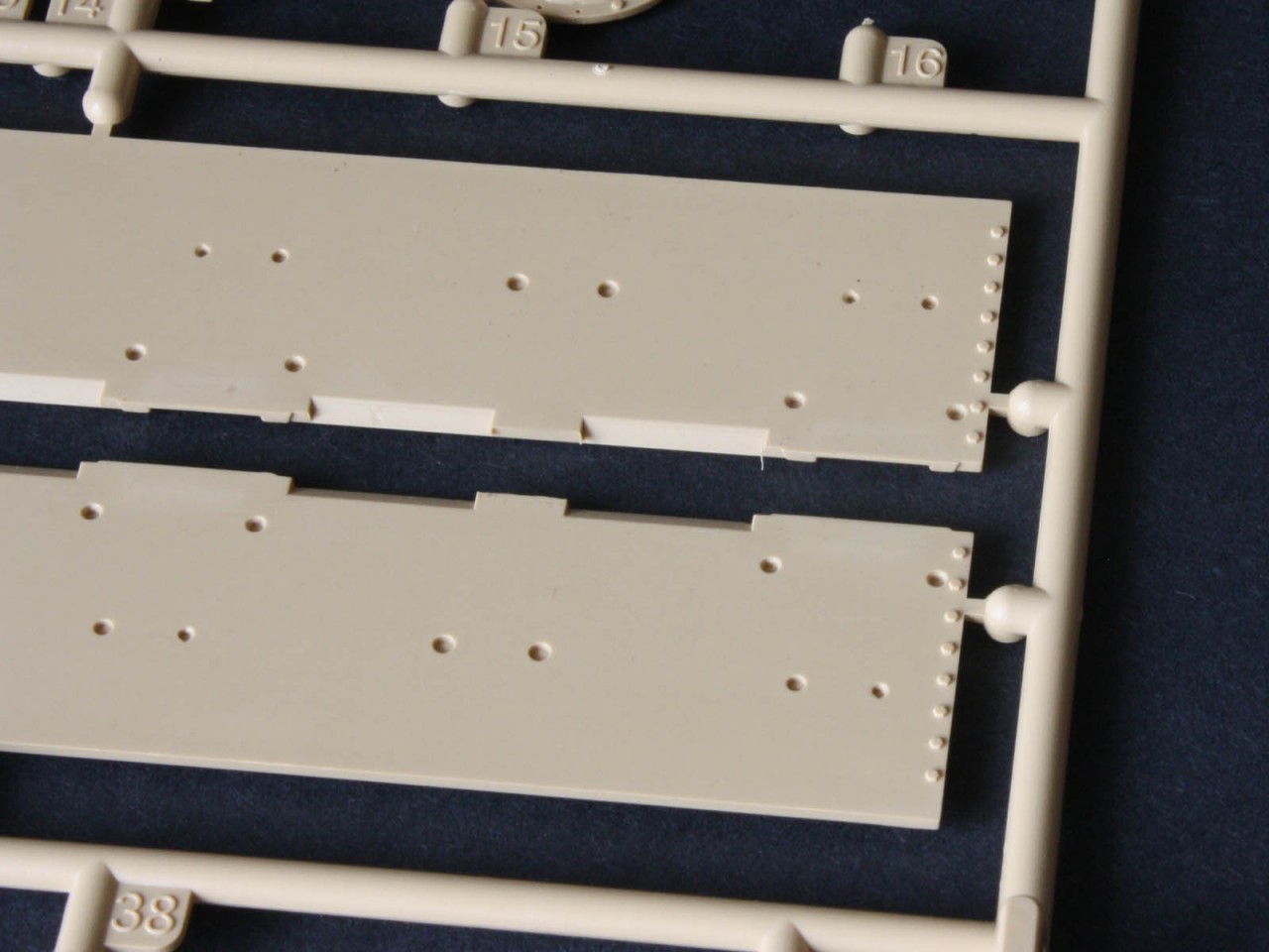
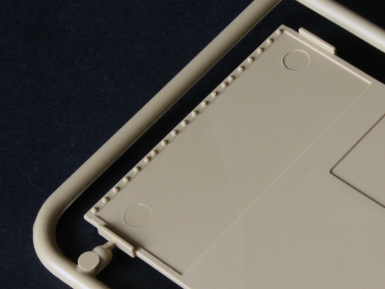
The hull is a work of art. The welds are excellent, the textures are realistic, and the detail is sharp. The lower hull has the vertical bolts for the final drive assembly (FDA) on the nose, and even has a row of bolts around the inside! This has led to speculation that an interior is planned, but it would require some modification of existing parts. It is more likely a result of changing design goals during the development of the kit. Interestingly the cast FDA covers on each side are detailed not only on the visible outside, but also on the hidden inside even though the instructions call them for the wrong sides and the part numbers need to be reversed. Sadly we cannot just pose the tank with the FDA removed for maintenance because there is no internal detail of the brake housing or gearbox, and all the bolts are moulded in place rather than as empty holes so some drilling wold be required. But once again we get excellent casting marks on all the cast parts of the hull. This includes the hatches, which have the internal spring hinge mechanism that nobody else has offered. All the periscopes are separate, along with their rotating mounting plates, flaps, and brush guards most of the competition mould the two fixed hull-mounted periscopes in the closed position, but not here. RFM offers a choice of plastic or PE brush guards, but the PE is too flat so plastic is the way to go.
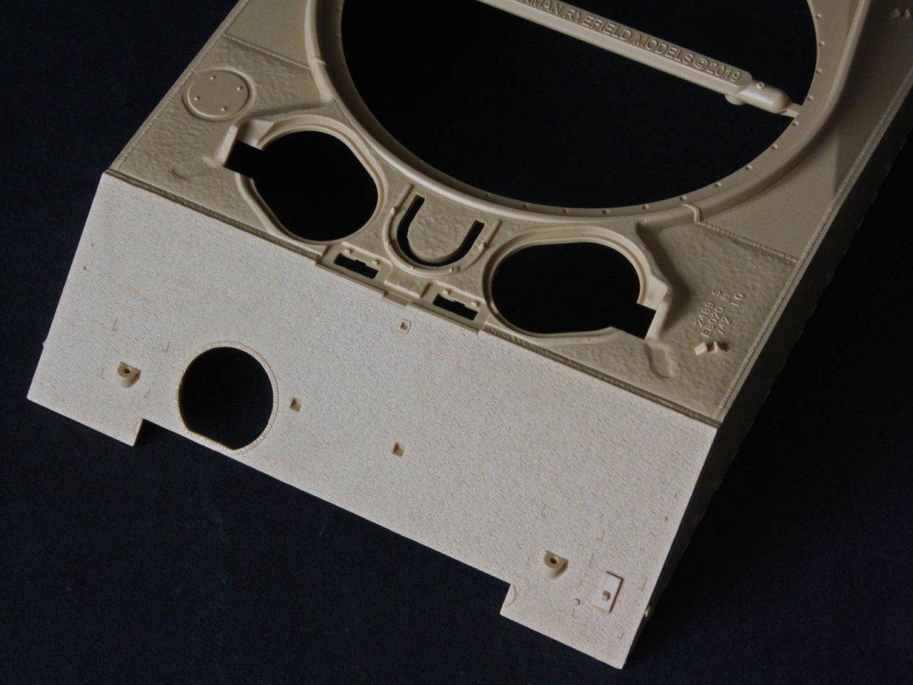
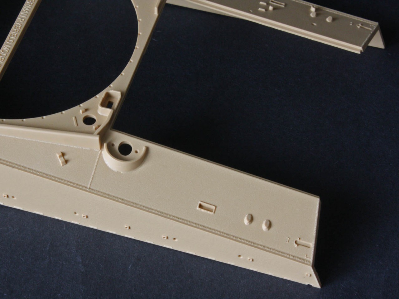
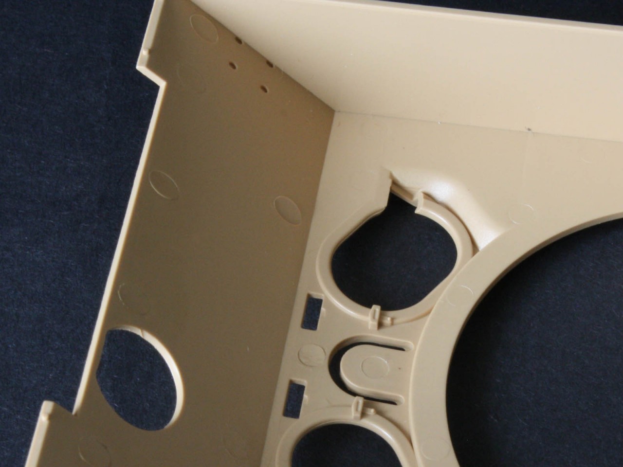
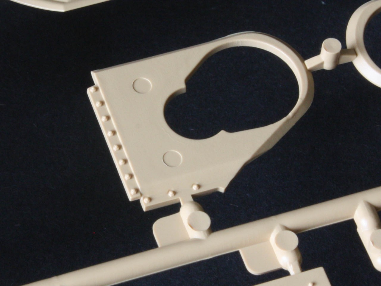
The hull MG mount is an unusual bit of engineering, with the entire circular area a separate piece of plastic. And the front glacis has an inner lining piece that again suggests an interior was initially planned. The front lifting rings have two sets of holes that need opened from the underside one set along the outboard edge of the hull, and the other set back about a scale foot from the edge. Early large hatch hulls had their rings mounted inboard, but by the time tanks like the one in this kit were being built the rings had moved outward. The extra holes suggest RFM is planning to use the hull for an earlier M4A3 variant in future.
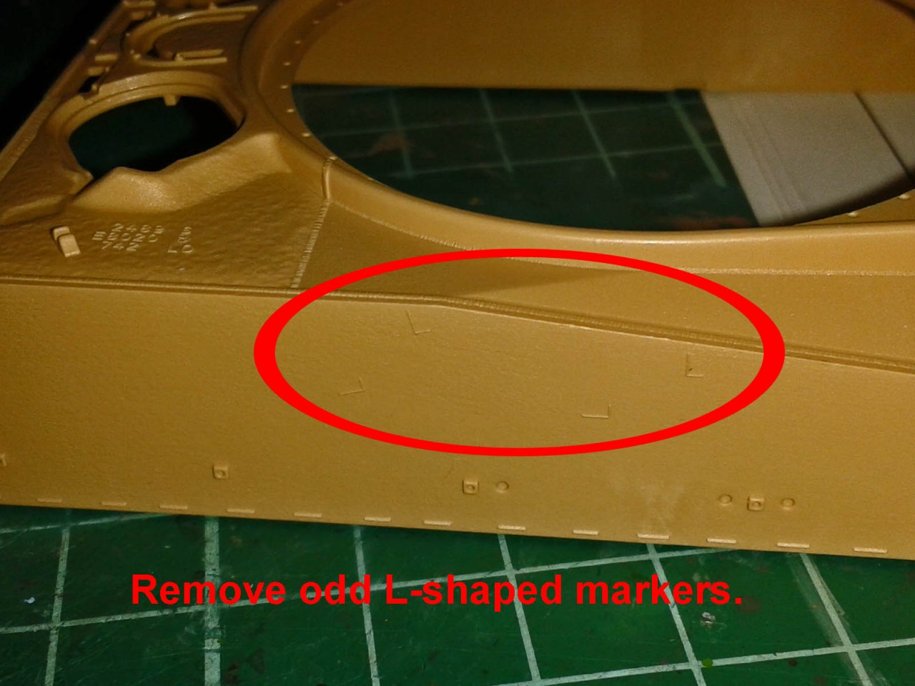
On the left hull side there are some strange raised location marks to sand off these are a mystery since they are in the wrong location for any variant I can think of. Not a Tokyo Depot sprocket bracket, not an armoured first-aid kit box but clearly RFM is thinking of something to release in future. One part that will test patience is the PE bracket holding the mirror arms why these microscopic items werent moulded on the arms is beyond me. And the front headlight brush guards are supplied only in PE so need bent to shape, but there is no tool to aid this. If you happen to have a spare forming tool from Tasca/Asuka it comes in handy! Oddly the tail-light guards do have a plastic alternative
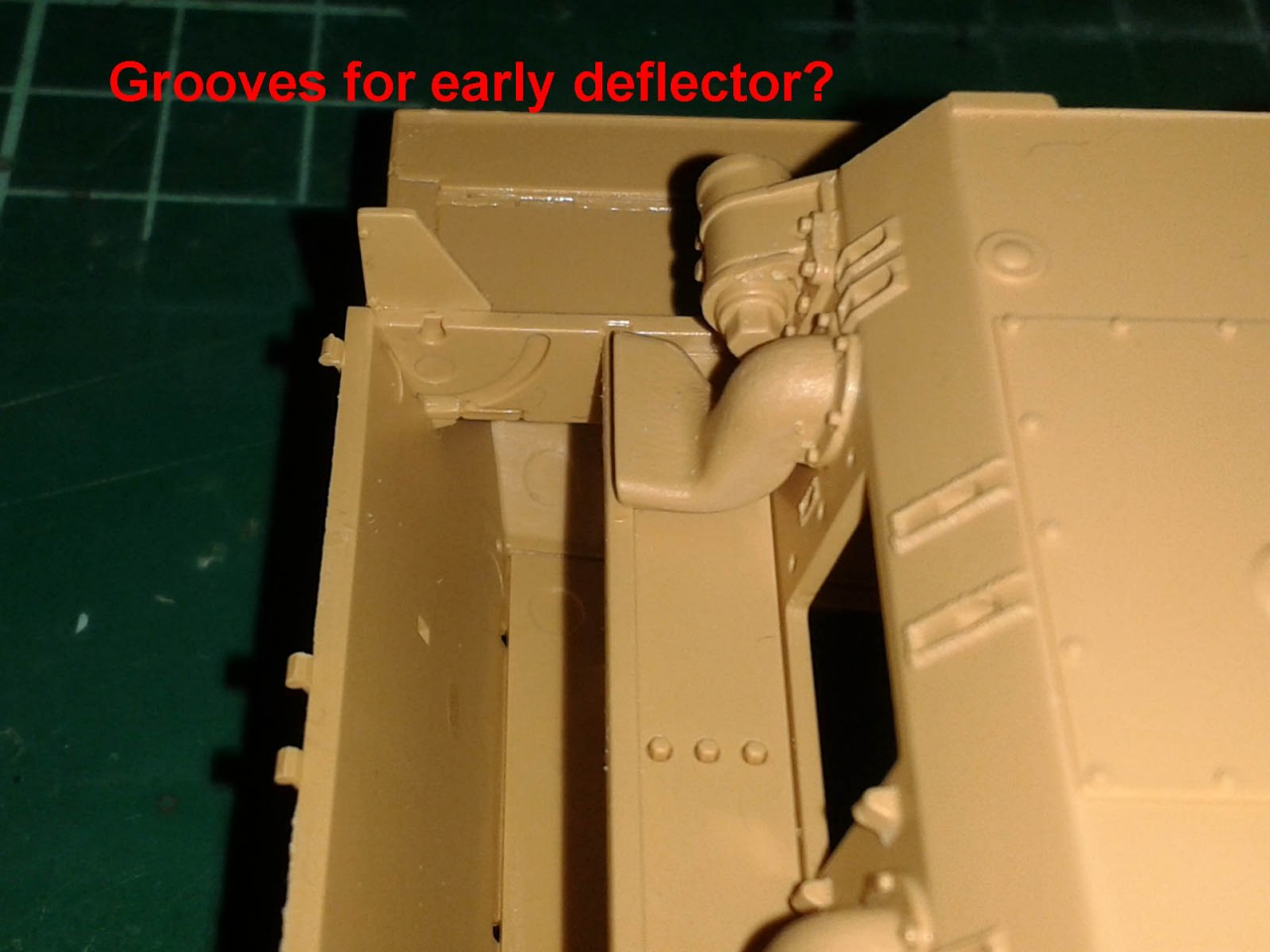
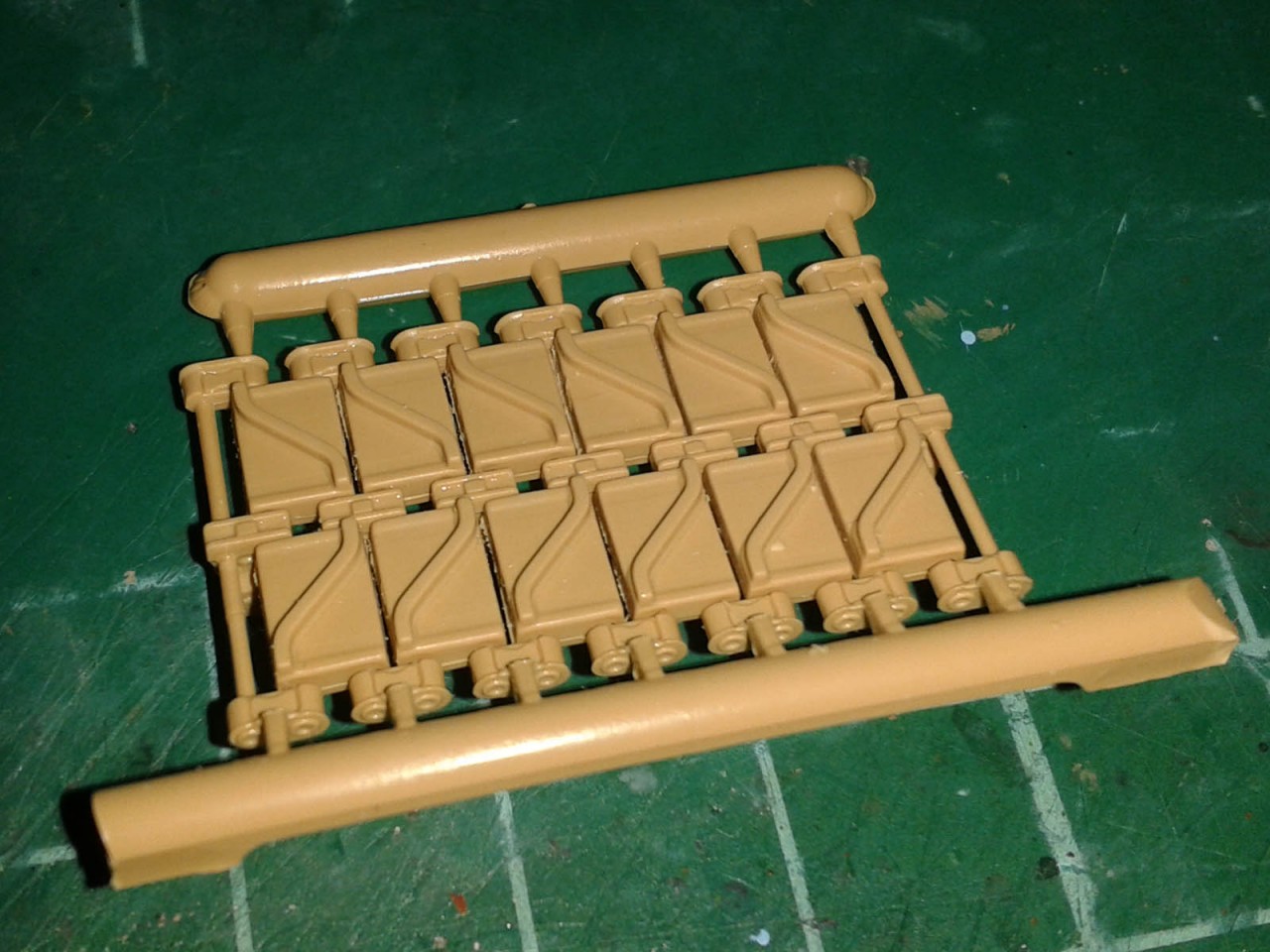
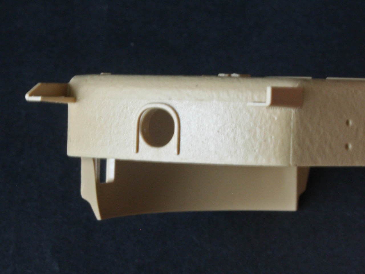
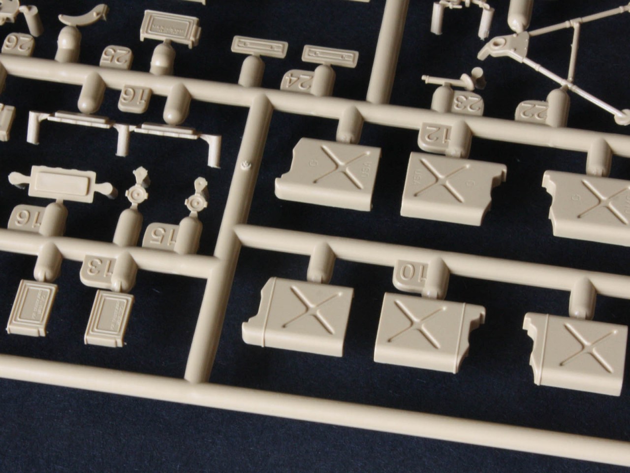
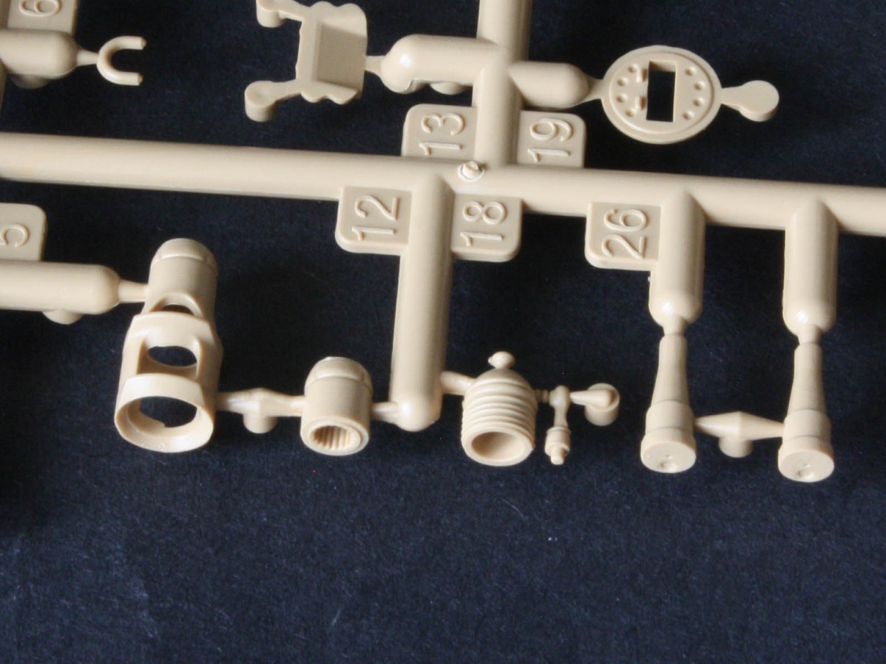
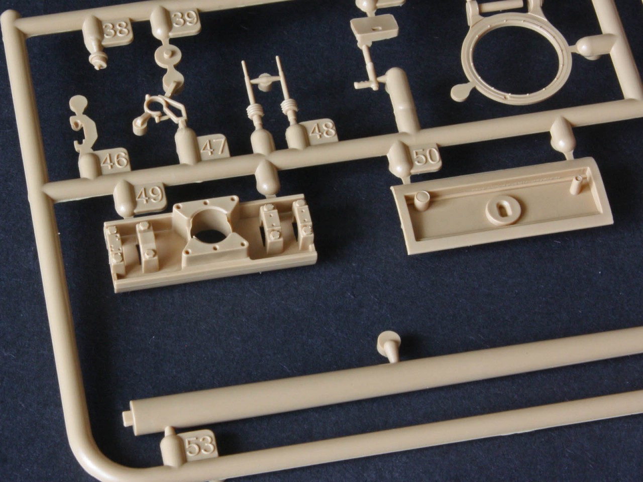
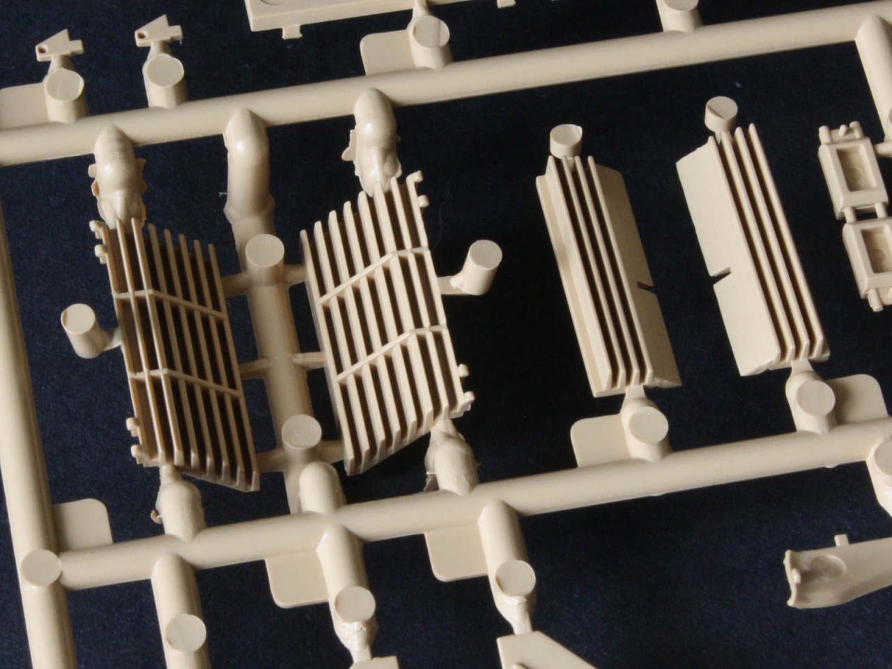
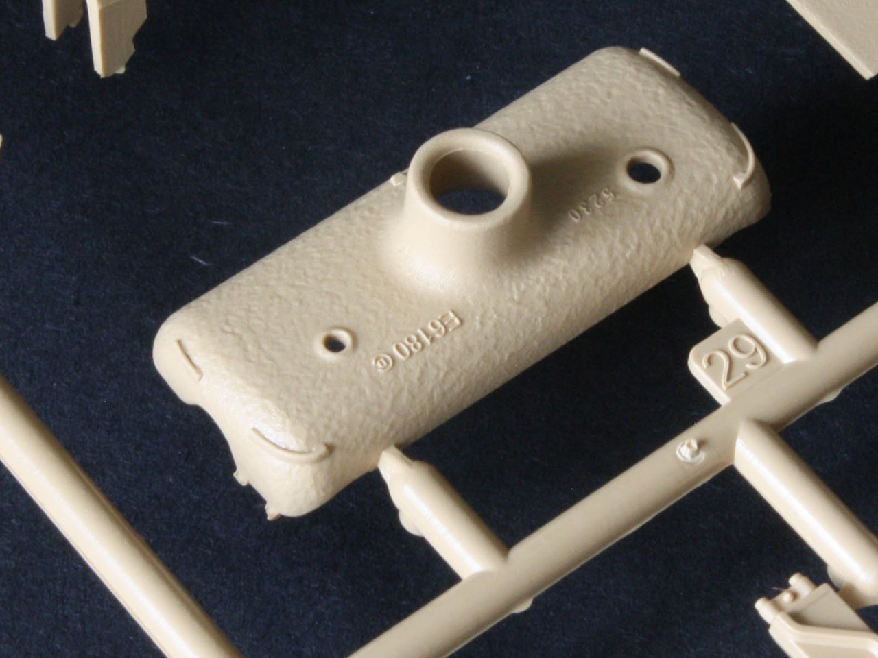
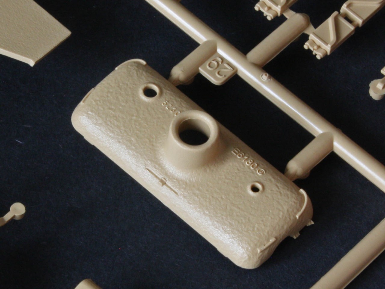
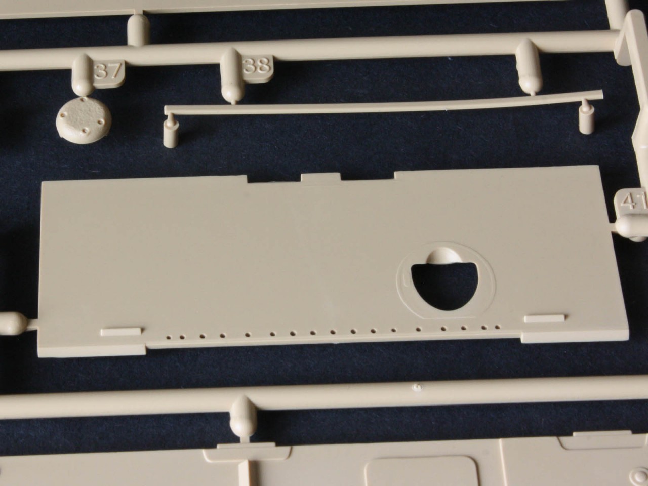
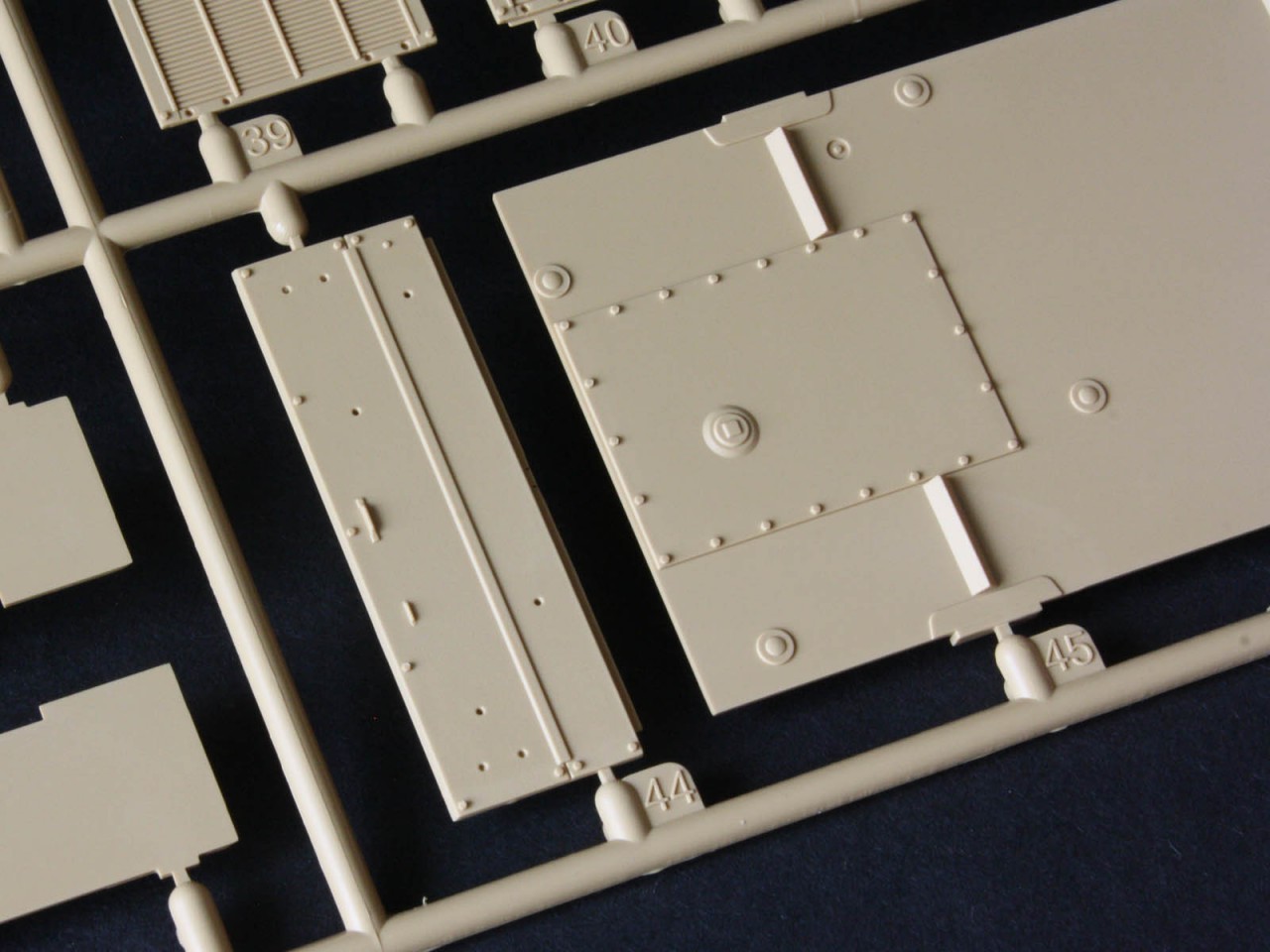
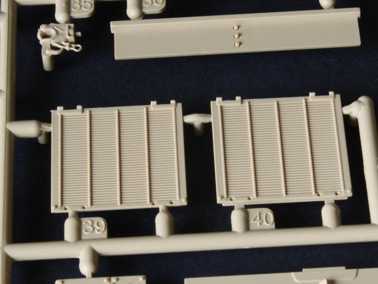
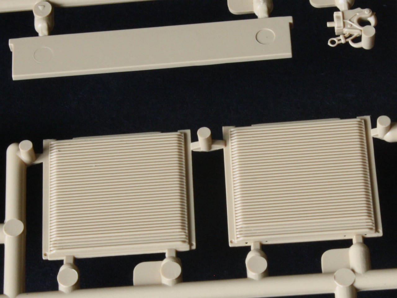
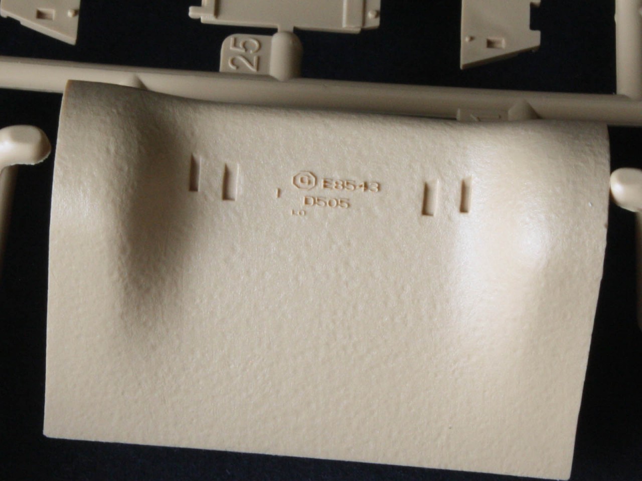
Round the back we get excellent renditions of the armoured exhaust deflectors, two slatted boxes that redirect the exhaust air out from under the hull overhang that protects the radiators. Trouble is, these late deflectors are almost unknown in WW2 the more typical deflector is the curved stack of sheets that Asuka includes but RFM does not. The deflectors can be modelled in the up position (for engine maintenance) or the down position for general use. And since the engine access door in the rear is a separate part it could form part of a diorama with mechanics working on the non-existent engine. RFM provides nothing to fill the engine bay, but there are aftermarket sets out there. The same goes for the engine doors on the back deck, as these have slat detail on the inside. The on-vehicle tools look good, but lack any means of securing them the classic floating tool syndrome that also afflicts other brands. Either replace them with resin tools that have the straps moulded on, or break out the Evergreen strip to make your own securing straps. RFM moulded the fuel caps as separate parts, like the Tasca/Asuka kit, but unlike its competitor the RFM kit has an open hole where the other has a rendition of the filler top so the flap could be opened for a diorama. One thing mentioned by somebody in OldWarlokes build log is that the handles on the rear deck should be flat to the deck, but this is inaccurate. Early M4s had handles that slid up and down in holes so they were out of the way when not in use, but photo evidence of the M4A3 shows they no longer bothered the handles were welded to the deck in the more traditional manner, and the kit is correct.
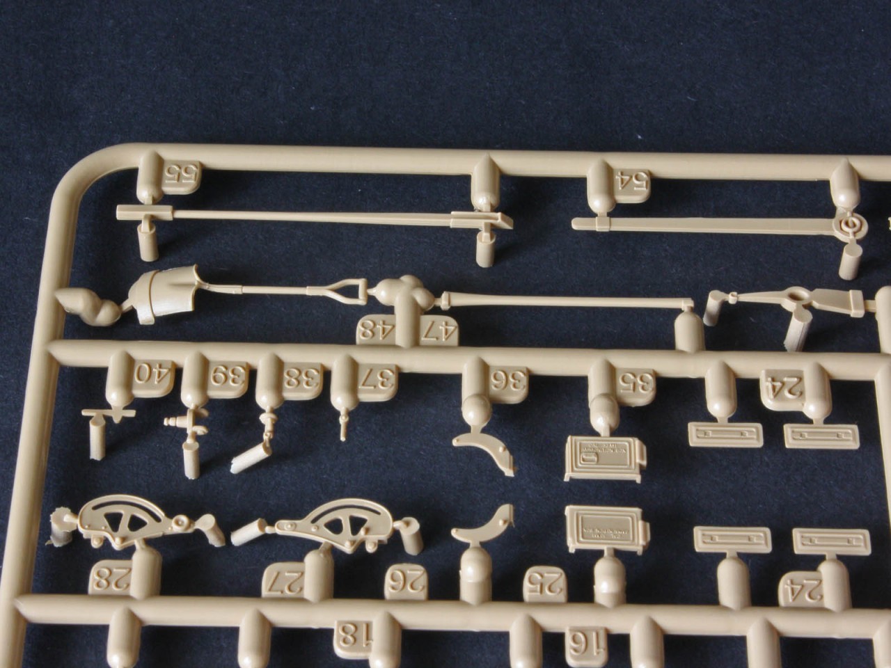
RFM uses PE for the rear shelf brackets, including two miniscule bits for the mountings that are a challenge. The butterfly nuts for the cleaning-rod rack are separate bits of plastic that are just right to feed the Carpet Monster. There are parts for four 5-gallon cans to fill the shelf two water cans and two fuel cans but for some reason only two of them have the raised seam between the body and top that was a hallmark of all US cans at the time. One last detail on the hull is the fire extinguisher pull block (part E2) which has excellent detail of the holes the cables pass through, but lacks the pull-handles themselves!
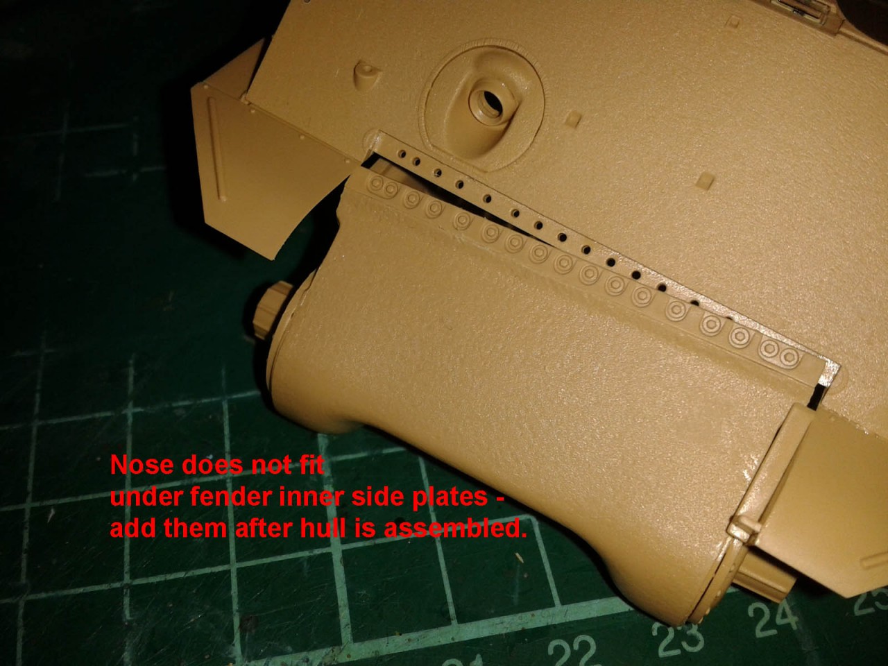
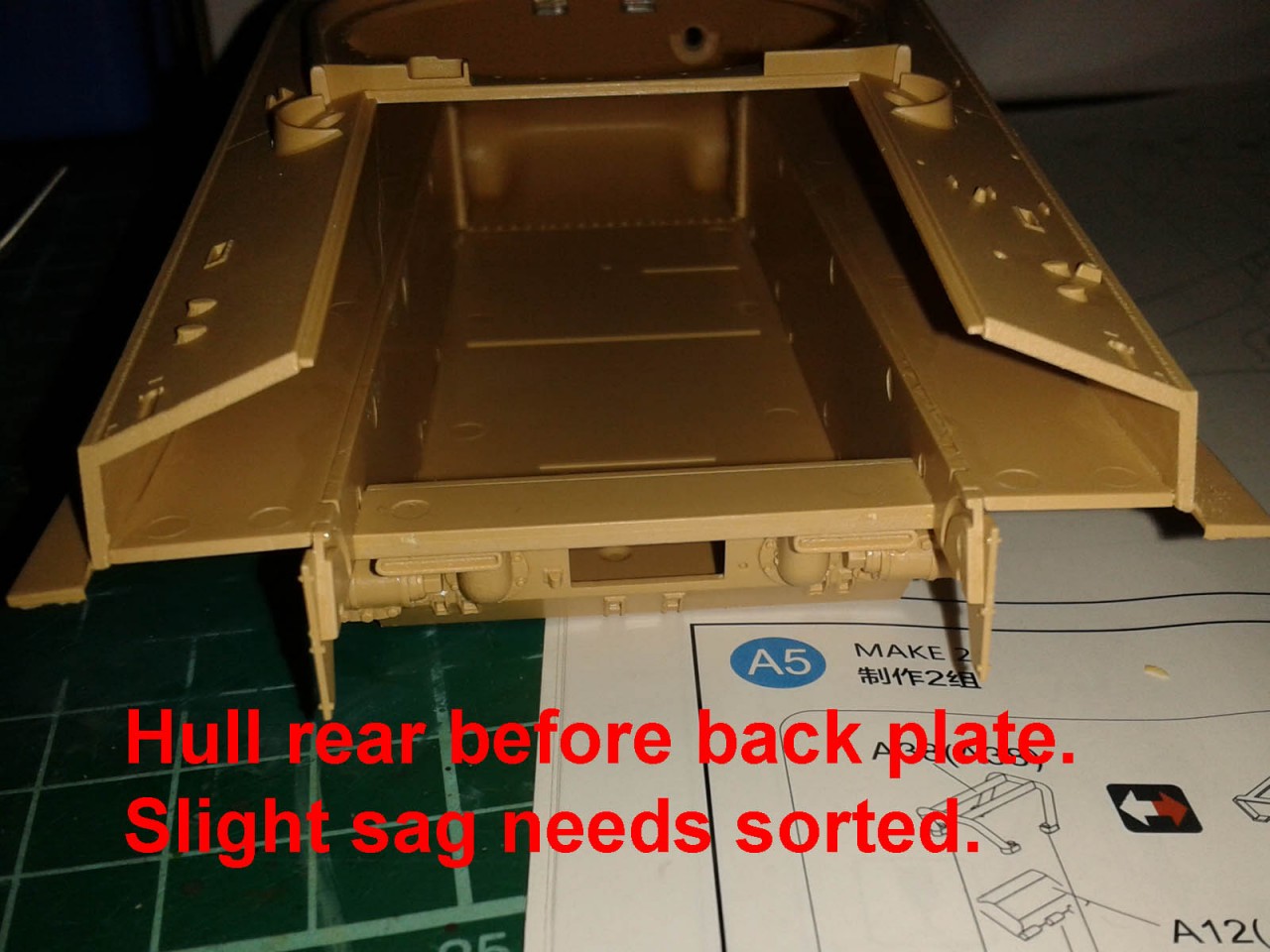
For my build I went with getting the main hull parts assembled before adding any details, and I am glad I did! I had to add the hatch mechanisms in the upper hull (since these cannot be accessed afterwards) but otherwise I left off everything the instructions called for. I found it easiest to glue the lower hull sides to the floor by laying the side on the table, standing the floor in place, and running a bead of liquid glue into the joint. Be careful it does not flow out and melt the side onto your cutting mat! Everything is very wobbly until the rear panel is added, and the front does not stiffen until the FDA assembly is added, so it pays to have made this first. On the upper hull I found that the inner face of the front fenders cannot slip over the lip at the top of the FDA, so while I could slide it in sideways I had to leave the opposite face part off until the hull was assembled. The rear will be wobbly until the rear plate is added, but to get access for gluing the sponson floors to the lower hull sides I left it off and then added it while forcing the parts into alignment. (I did all this in one sitting, so the glue was still soft while I forced things into shape!) After it was all stable I made sure the fenders on the sides were still sticking out straight and added all those diagonal braces. Only then could I turn my attention to the engine deck and other details.
Suspension
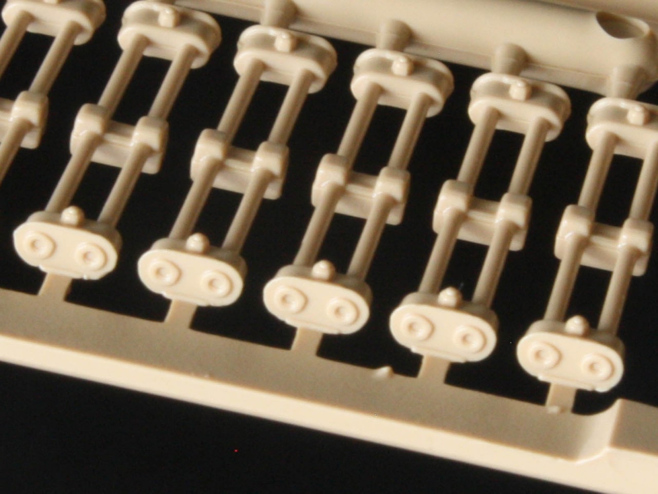
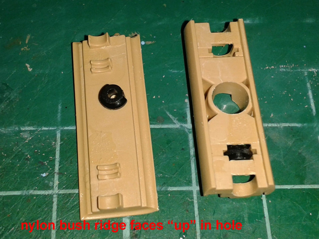
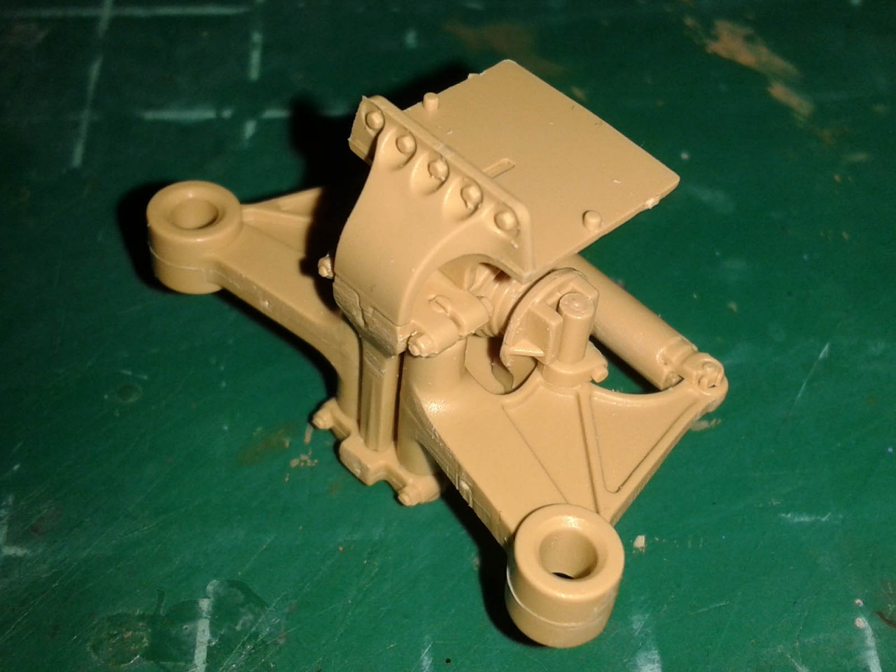
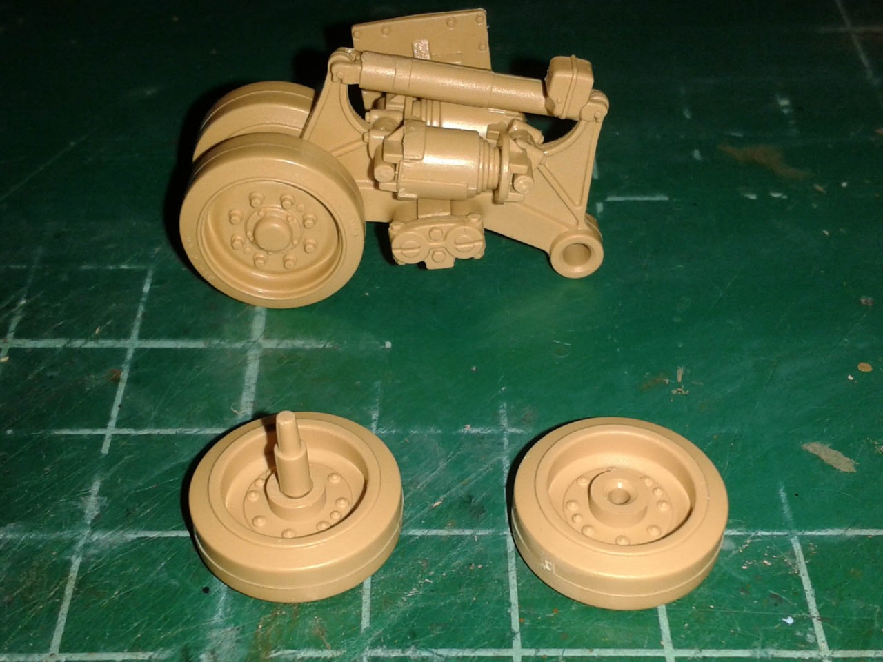
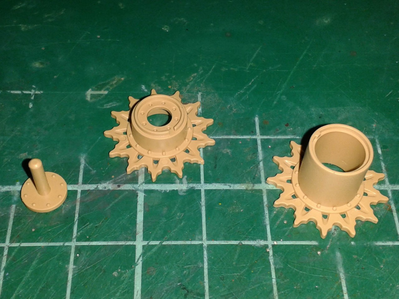
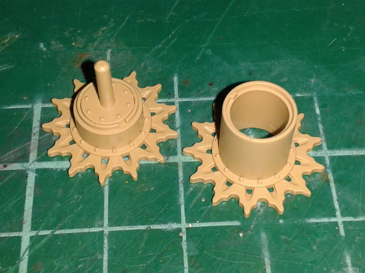
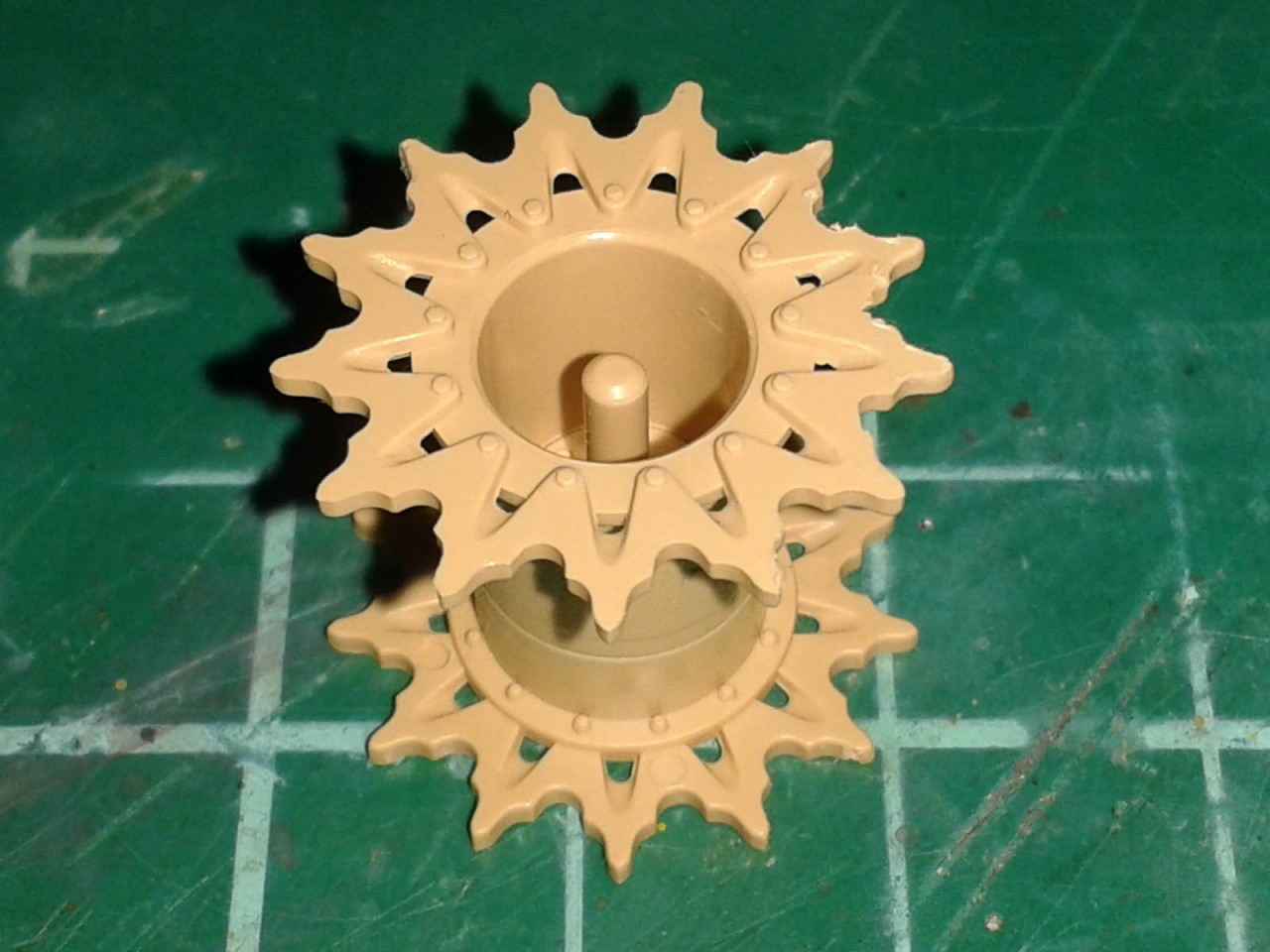
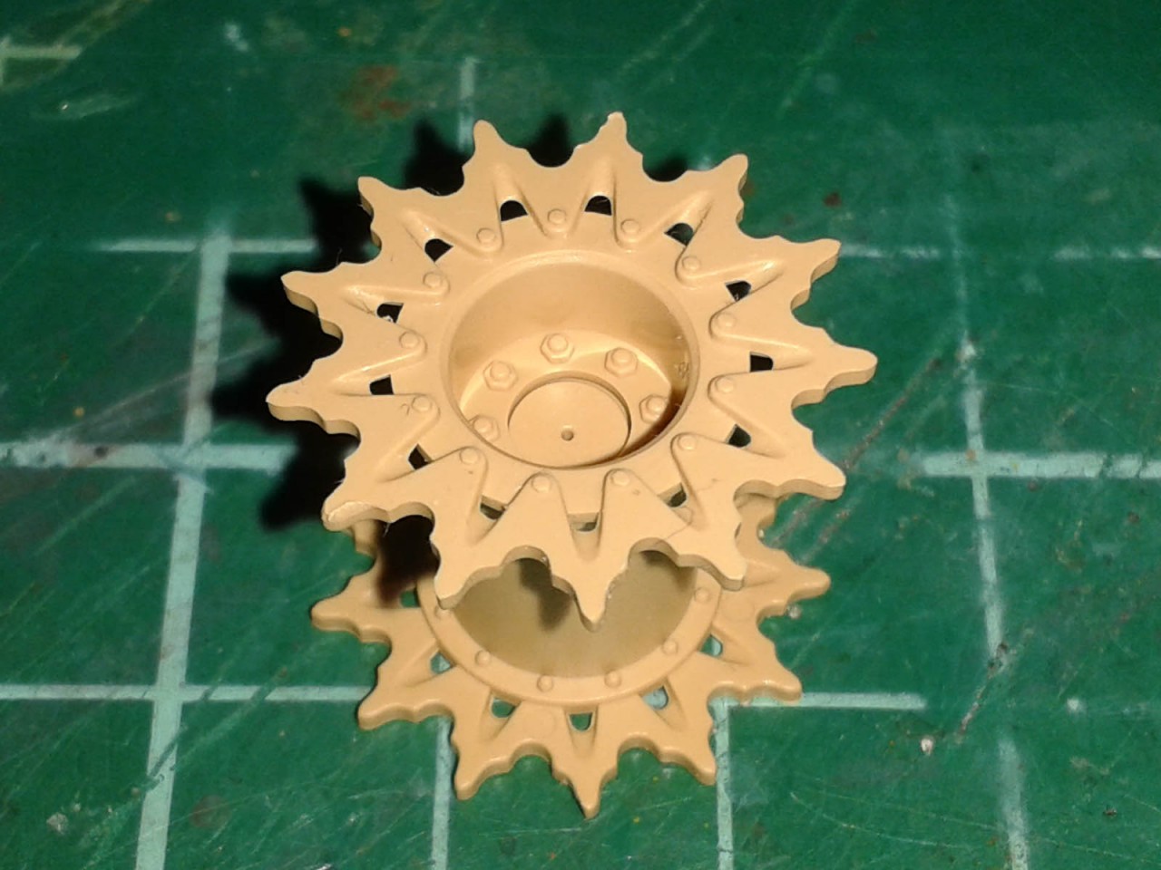
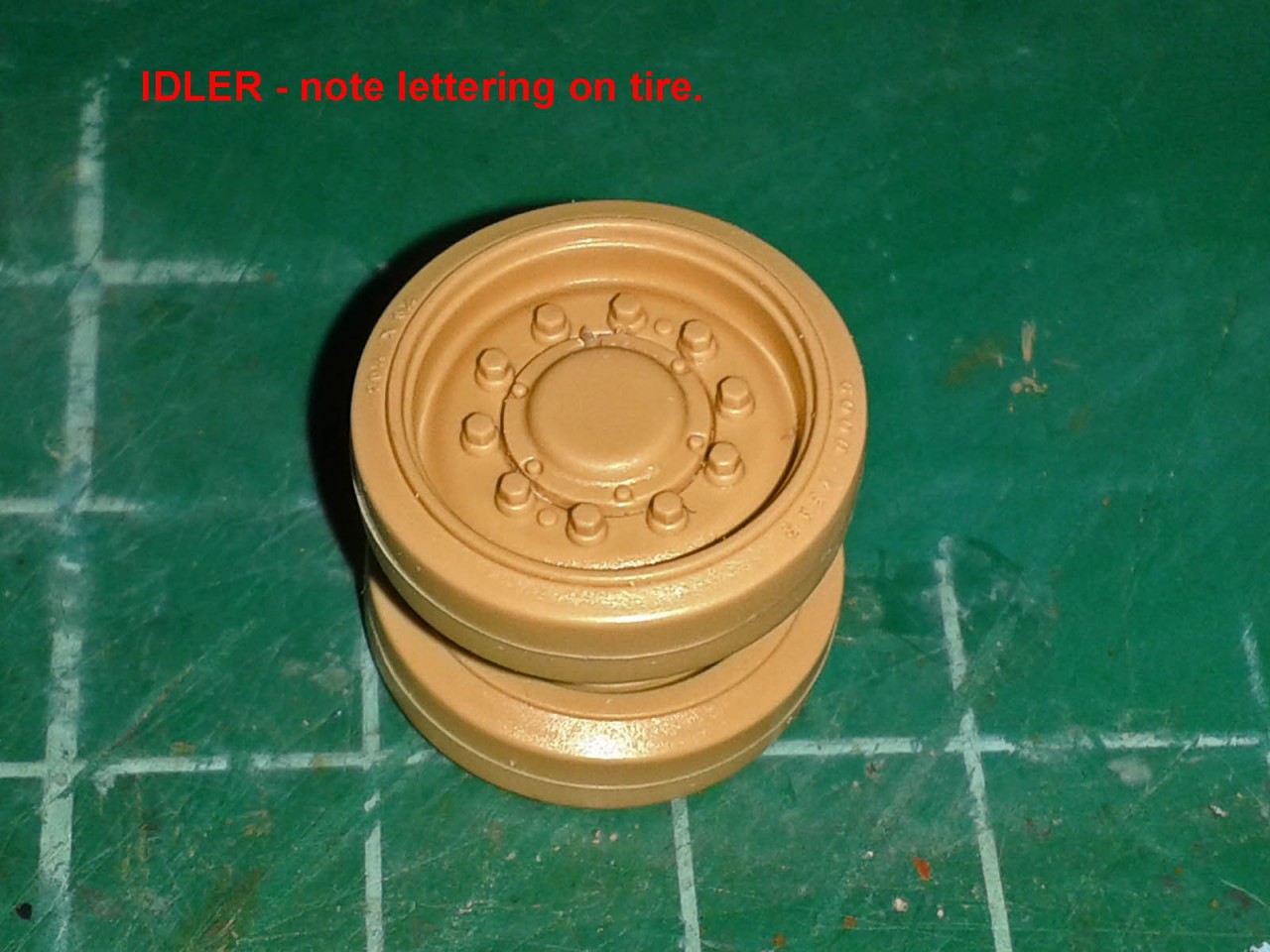
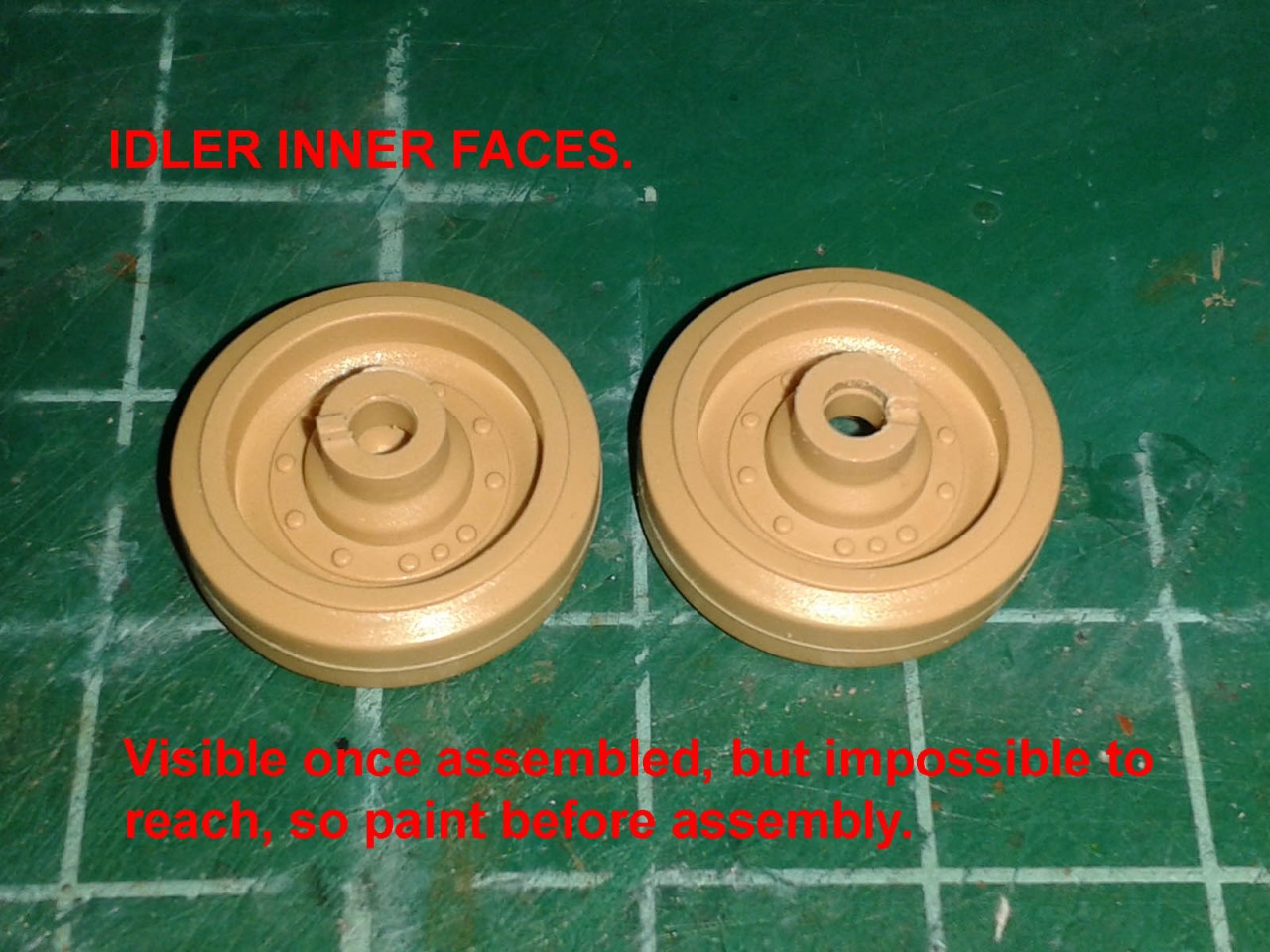
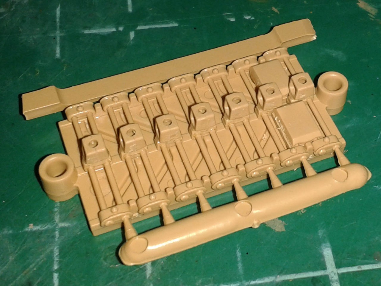
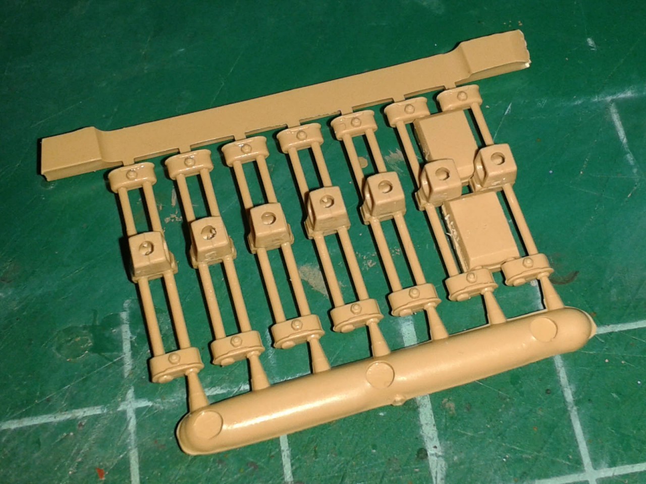
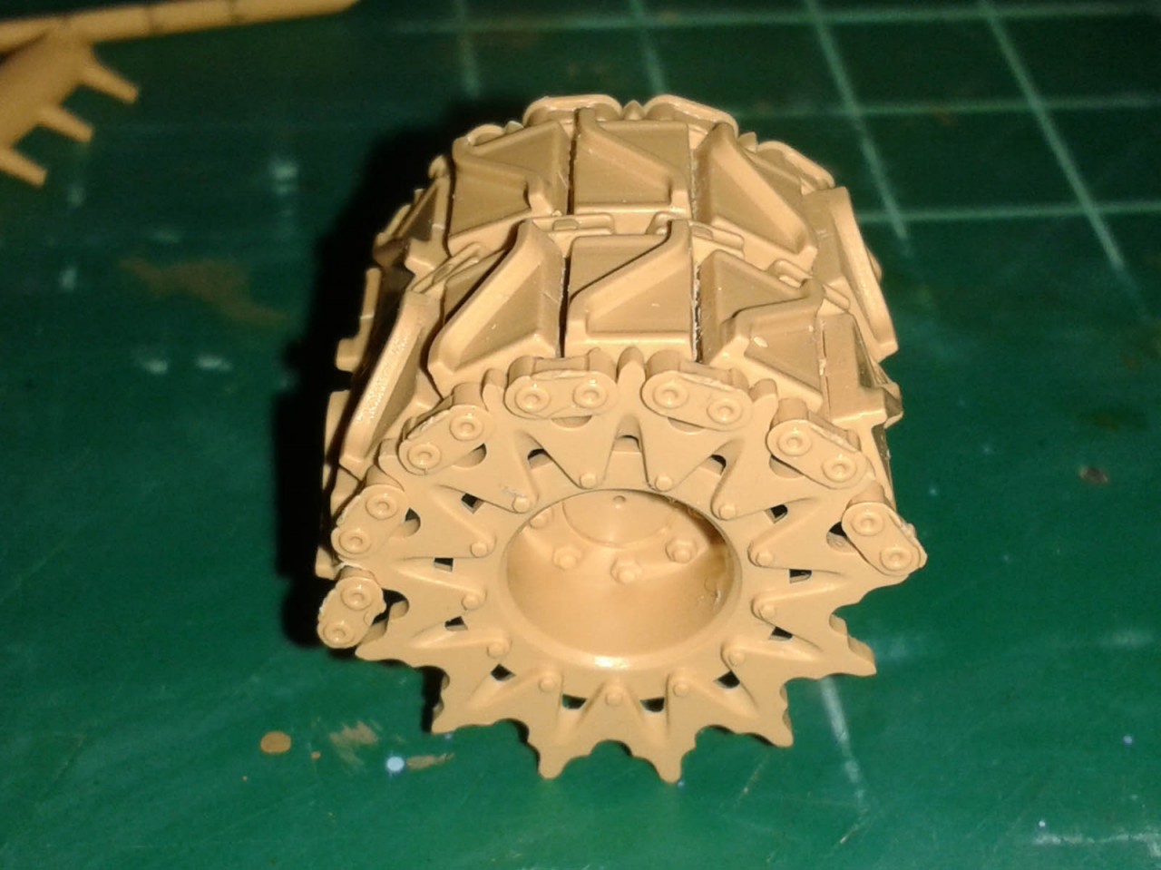
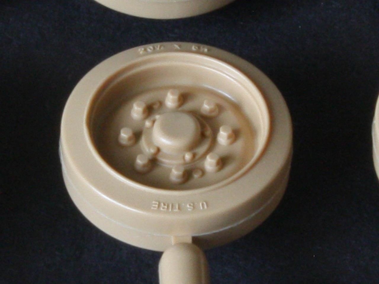
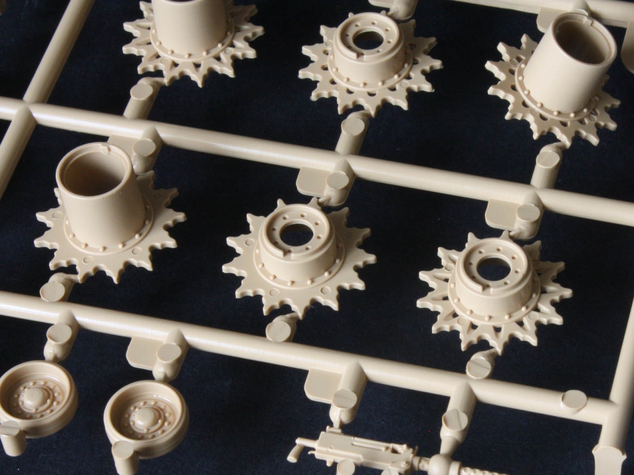
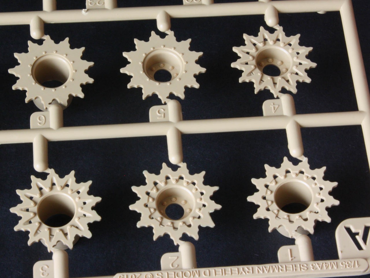
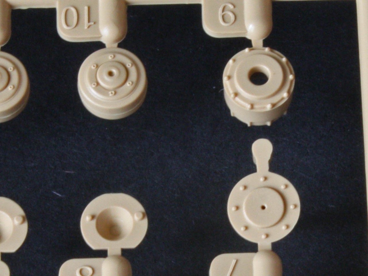
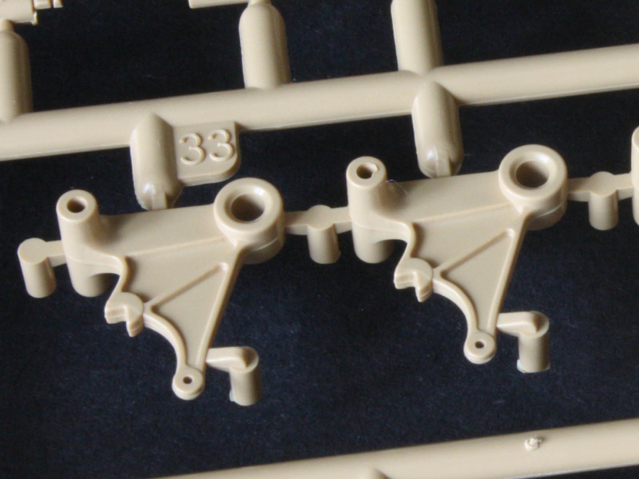
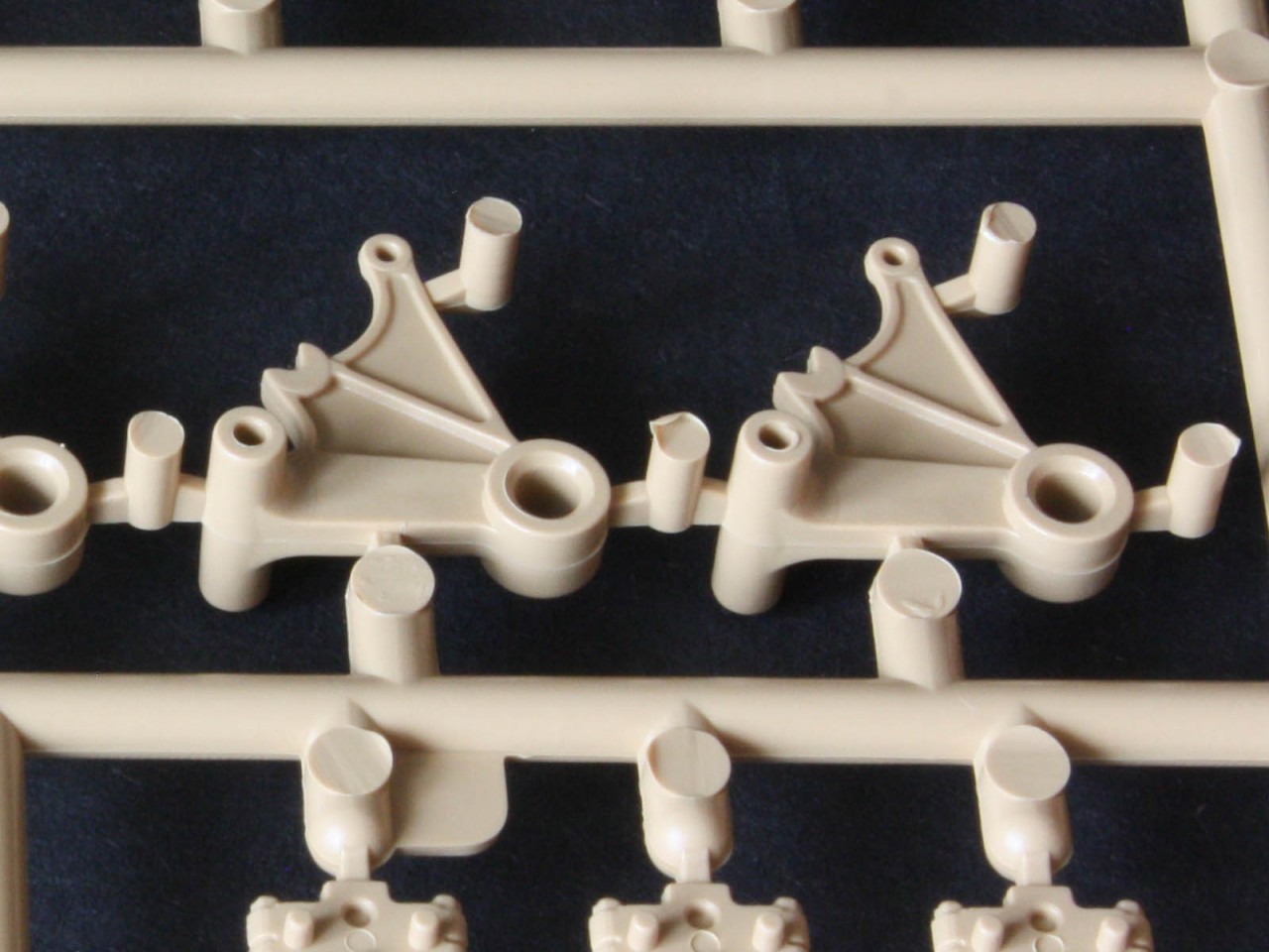
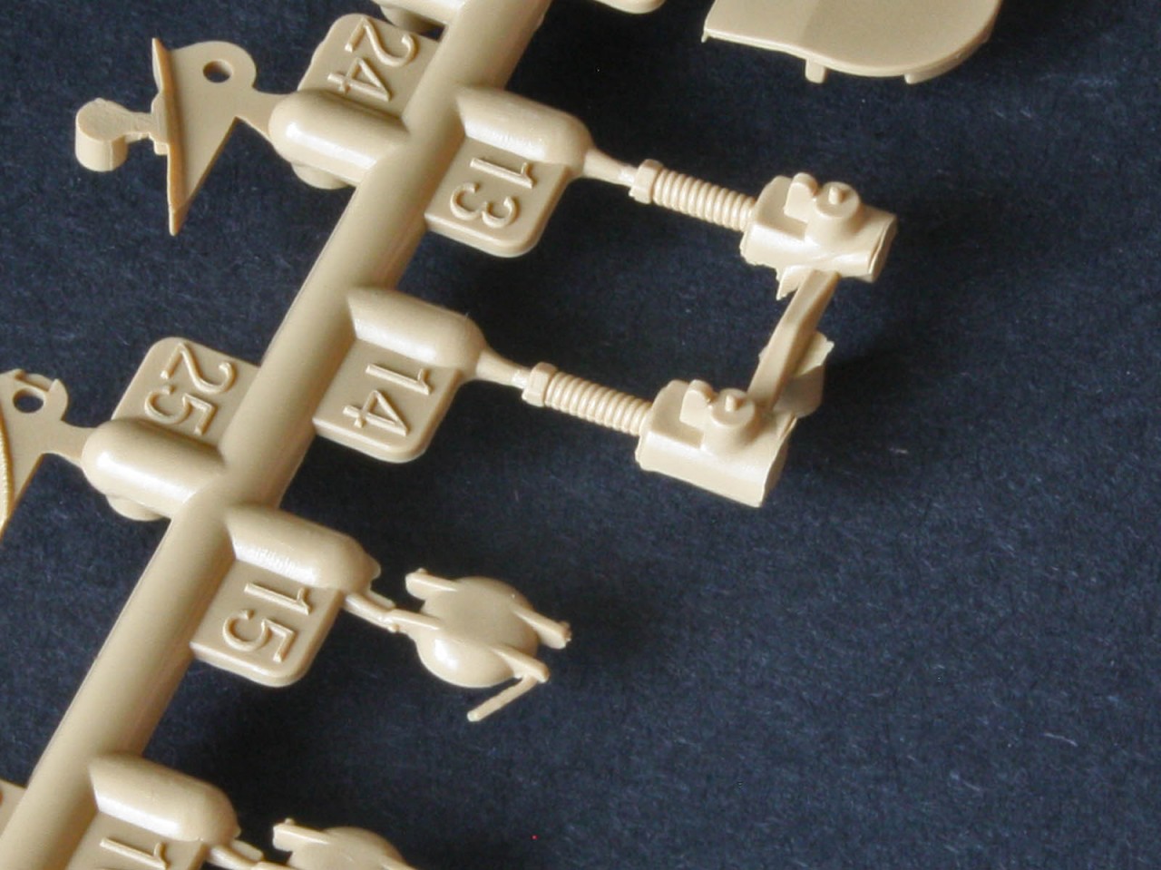
The HVSS suspension is very similar in construction to the Tasca/Asuka design. The shock absorber across the top is a single piece, with added end parts that trap the top of the cast suspension arms so they can pivot (if you are careful with the glue). The bottoms of the arms are trapped by the bracket body and another capping part, and with the springs fitted without glue the whole thing can rock back and forth as one wheel is pushed up and forces the other wheel down. It kinda looks like full articulation, in the same way the old Italeri VVSS kinda looked good despite acting like a rocking horse. Fit of the bogie mounting plates is good, but I found I had to bevel the hull edge a little to get them to sit flat due to the inner angle of the bogie plate being less than perfect. (It is a glued joint after all, so I could either carefully square-up the angle by skilful shaving, or bevel the hull with a few swift passes of the file.) The arms lack casting marks (unusual for this hyper-detailed kit), but on the plus side the road wheels are beautiful! They even have raised moulding marks on the rubber tyres. The fit of the axles into the wheels is excellent, not even needing glue, so naturally these are left loose for painting. The idlers are similarly good, and have an adjusting arm to take up the slack after the track is fitted, so dont glue that arm! But I discarded the idea of trapping the idler onto the axle with the Italeri-inspired plastic ring provided, as this means the hub cap must be left off until after final assembly I prefer to have it all glued up ready for painting, even if that means the idler is either loose or glued to the axle afterwards. And we get a choice of three sprocket types plain (parts A5/A6), fancy(A3/A4), and fancy with flat spots (A1/A2) as seen on the earliest M4A3s. For this tank we only need the fancy ones. The sprockets are held on with polycaps, but for some reason the instructions say to leave the hub cap (part A7) on the FDA cover, when it needs to be glued into the sprocket for painting I glued it to the inside of the outer sprocket part before adding the inner part. On the plus side the details on the hub are such that you could model a maintenance scene with the sprocket removed.
One thing to note is the orientation of the three mounts for the inboard track support rollers (parts A8) these have a large flat side that should face up according to tech manual drawings, and a much smaller flat edge that faces down towards the top of the bogie plate. Another interesting issue is the parts for the volute springs A19, A20, A21. While they should be identical, and most kits have just one part number, the detail-fanatics at RFM have noted that the real coiled-sheet spring could be fitted any way round, with the outward sign being the edge of the sheet that might or might not be seen. To mimic this variety RFM give us three different renditions of the spring, whose only practical difference is the location of this barely-noticed edge detail! The instructions dont make it very clear, but feel free to mix and match them to please the microscope-wielding judges at your next model show.
Tracks
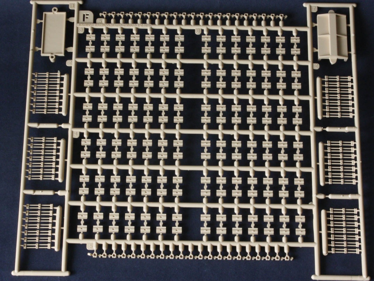
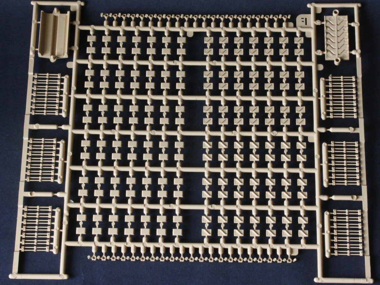
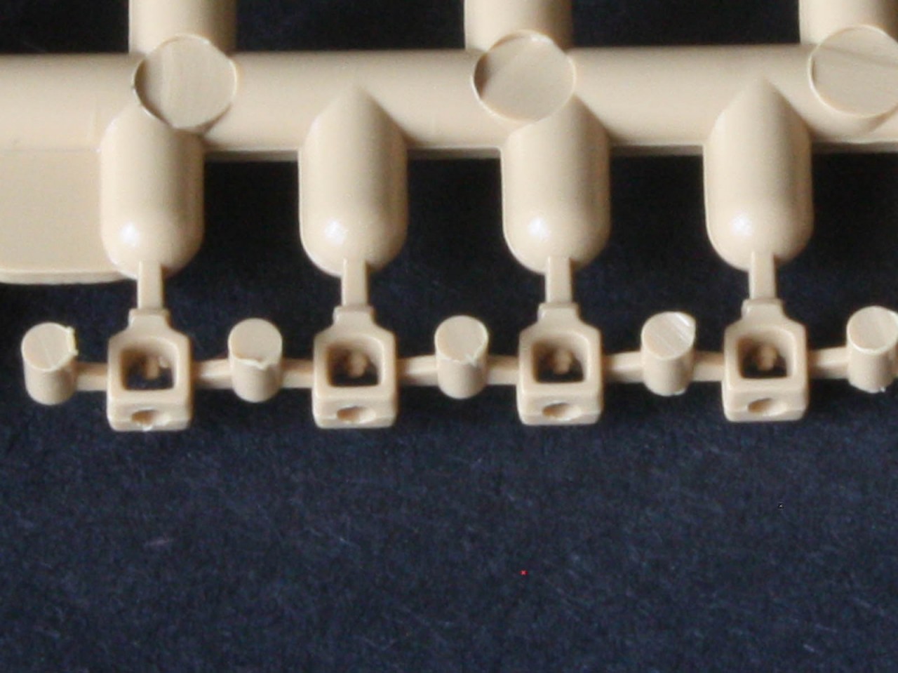
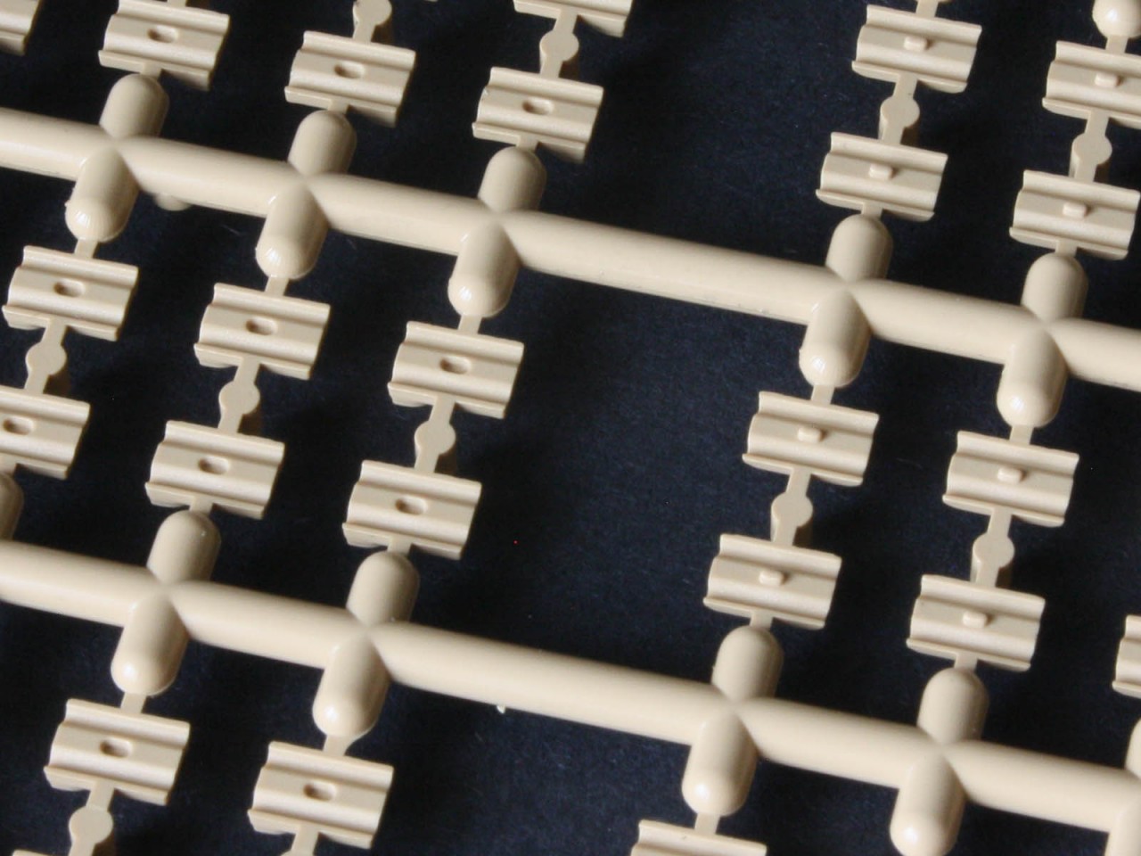
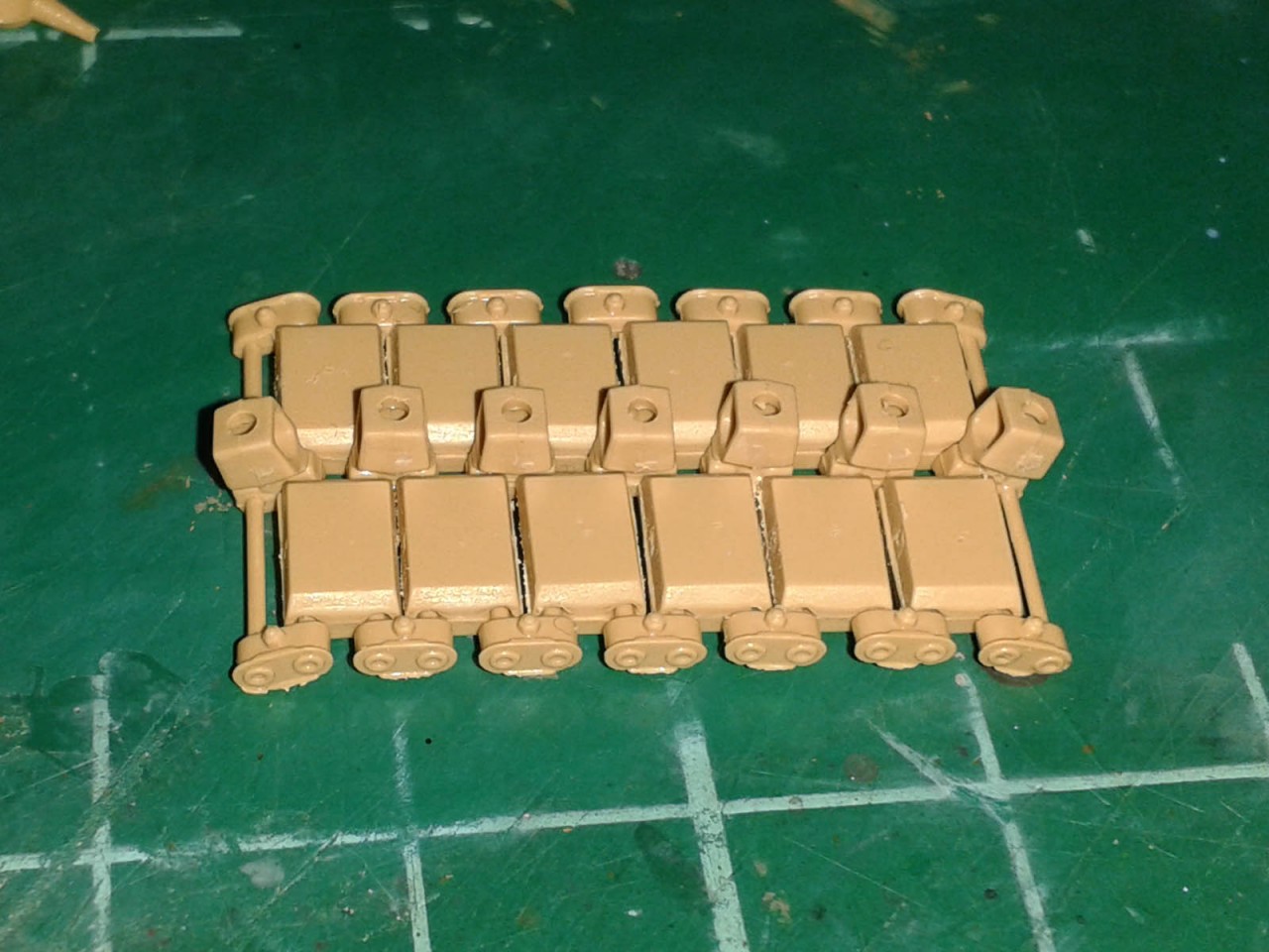
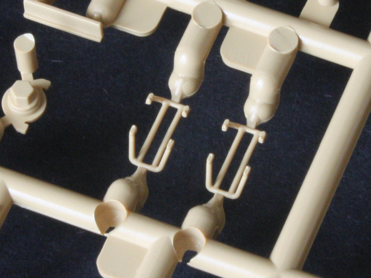
Then its on to the tracks! RFM has looked long and hard at Bronco for inspiration here each link is made from pad halves that trap a set of bars with the end-connectors moulded on. The result should articulate nicely see OldWarlokes build log for how he did it.
Each of the four track sprues holds six sets of seven paired bars with end connectors, plus all the guide teeth and pad halves needed to make a total of 42 links. As each track needs 76 links that means two sprues give a track and eight left-over links. Note that the limits of slide-moulding mean that only one side of the end connectors has the correct recessed circular heads for the trapped bars, so effectively the track runs are handed. All the chevrons should point the same way on a track, although in combat there will be exceptions! (But note that the two cleats on each link are ALWAYS mirrored, since they form a single unit in real life
)
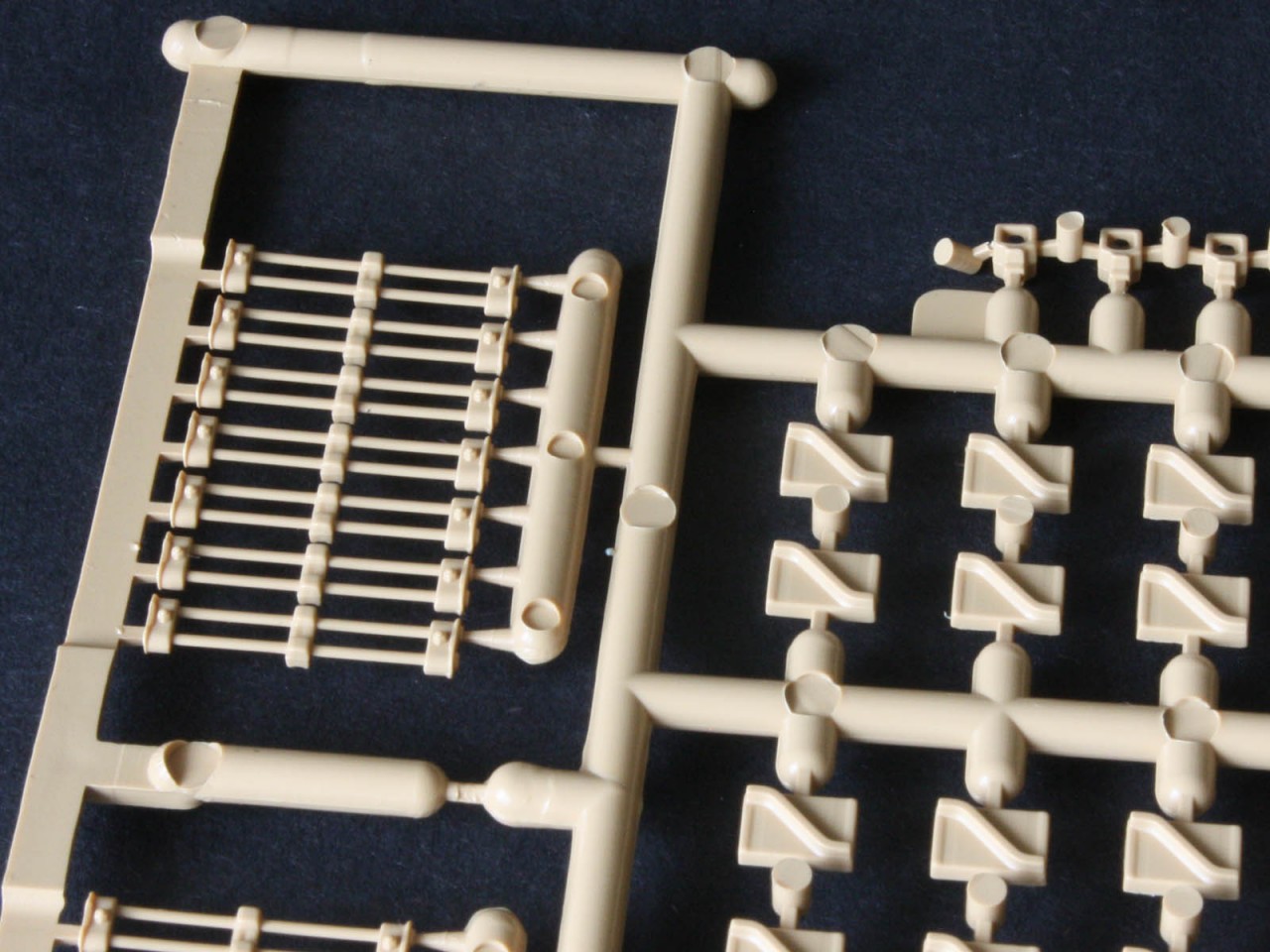
Start by adding the centre-guide cubes to the paired bars a very tedious activity indeed as each cube has three sprue gates to clean up! The openings face along the length of the track, so the flat solid sides rub on the inner edge of the wheels.
RFM provides a tool to assemble the tracks, but it is a bit confusing since it implies the links can be squashed together without glue but the pad halves do not fit together that tightly. However, if the sprue is cut so it holds the bars together they are correctly spaced for the pads. So, as OldWarloke showed us, simply use the bottom of the jig to align the outer chevron parts, place the bars on top, and add the inner pads with a drop of glue. I personally placed one set of chevrons in the jig at a time, added a drop of glue in the slot, then trapped the bars with the inner pads, because trying to glue all six sets at one time with quick-evaporating liquid glue meant some would dry before contact was made. The upper half of the jig has no use that I can find, so goes in the scrap box. I think I cannot cope with much more than one seven-bar set in a single sitting.
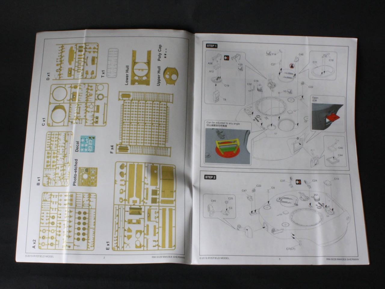
instructions
These take the form of an actual book 24 pages(!) of A4-sized CAD-generated illustrations that are mostly in greyscale with the occasional splash of colour to highlight certain parts. I cant recall the last time I saw so much info in a kit! The two paint schemes are on a separate A4 sheet. While there are English words sprinkled about the illustrations, I did spot a few instances where the only text was in Chinese characters with no translation I hope these were not important notes.
Assembly starts with the turret, then the upper hull, and finally the lower hull an odd choice. As usual I mix this up and build the basic hull box first as a solid platform for all the detail to be added. (Otherwise the upper hull becomes too delicate to handle, before the wrestling match of adding the lower hull.)
markings
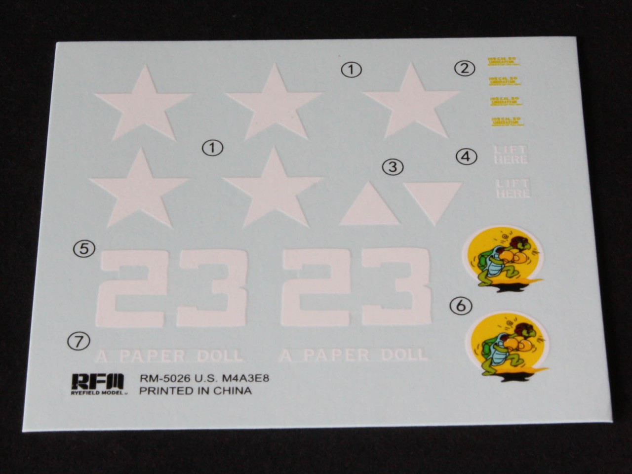
Decals are provided for two schemes, both indicated as Germany 1945. One is a tank called A Paper Doll, and the other is an anonymous tank with just stars. There are no bumper code unit markings, no serial numbers, and only a pair of lift here markings for the usual wealth of shipping data. I dont have any photos of A Paper Doll so cannot vouch for it. Tanks at the end of WW2 would have left the depot with big white stars on the hull sides, hull front, turret sides, and engine deck because the Ordnance guys were worried that these new designs with their wide tracks and big muzzle brakes would be mistaken for the enemy and get shot at by tired front-line troops, but crews often painted them out since they served as handy aiming points for German AT gunners. Given the very late production features this kit best represents either a new tank right at the end of the war, or a post-war tank either in Occupied Germany or in Korea in either case some aftermarket decals are needed.
conclusion
In many respects this is the best-detailed Sherman kit yet to hit the market and as a Tasca/Asuka fan I type that through gritted teeth. It is thoroughly covered in casting marks (as per the real thing) and has subtle surface texture on both cast and rolled-plate parts that will make weathering a treat. But it suffers from a certain amount of confusion about what it represents is it late-WW2, or Korea? And was it meant to have an interior or not? There are signs of an intended interior that will encourage some interesting dioramas, but RFM did not go far enough with these. And it has potential for parts to be re-used modelling earlier versions of the M4A3. Or, if RFM had added the armoured first-aid kit and infantry phone it could be a Korean War tank. This is certainly not a beginner kit due to the complexity and small parts, but will certainly appeal to the more experienced modeller especially as the price here in the UK seems to be significantly below its Asuka competitor. My main quibble is that it represents a version of the Sherman that barely saw any service in WW2, but it lacks the post-war upgrades and markings to be a Korea-era tank straight from the box. There is scope for backdating it or moving it forward with only a few new parts, so hopefully RFM will take the hint and add the early exhaust deflector to future runs, or perhaps some Korea decals to the existing kit?


Comments