Introduction
The AS90 is a 155mm lightly armoured SPG (Self Propelled Gun) which is built by BAE systems. The AS90 went into service with the British Army in 1992, which have so far purchased 179 AS90s. The AS90 currently equips six regiments in the RA (Royal Artillery) and RHA (Royal Horse Artillery) of the British Army. There are two types of this SPG, which are the AS90 and AS90 Braveheart. The AS90 Braveheart has a 52 calibre weapon as opposed to the 39 calibre of the standard version. There are only two trial versions of the AS90 Braveheart at this time, as the programme has been put on hold.
My intention here is to guide you through a review build of the AS90 from
Trumpeter in 1/35th scale, as currently in use by the British Army. This build is not completely an out of the box build, as some after market and minor scratch work has been included. The errors I have located through the build will be highlighted in order that you can avoid some of the pitfalls in this product.
I have also provided an In-Box Review of this kit
here on Armorama.
The Build
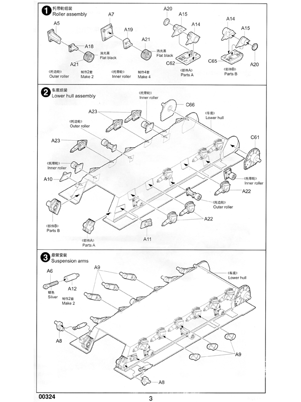
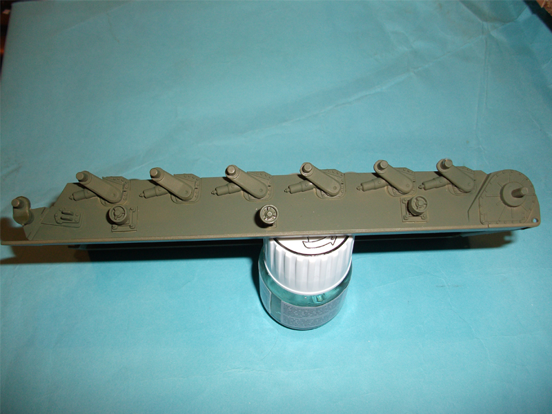
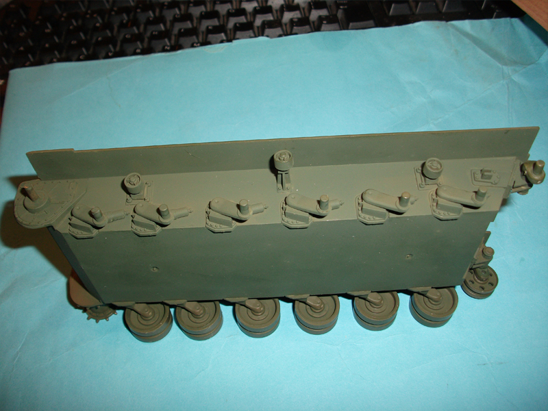
Stages 1 to 3:
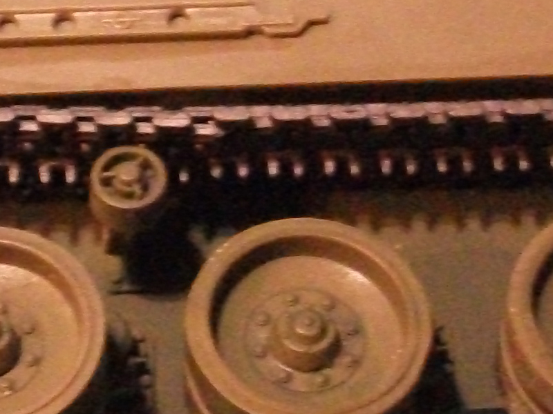
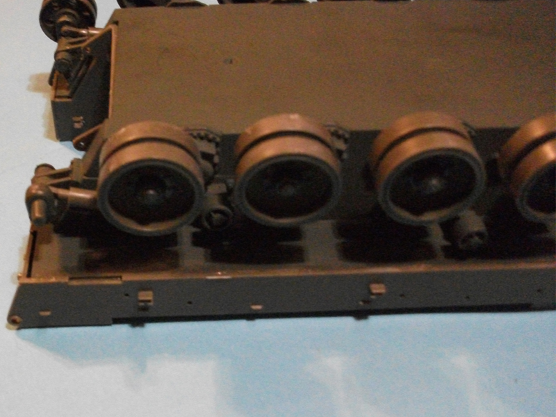
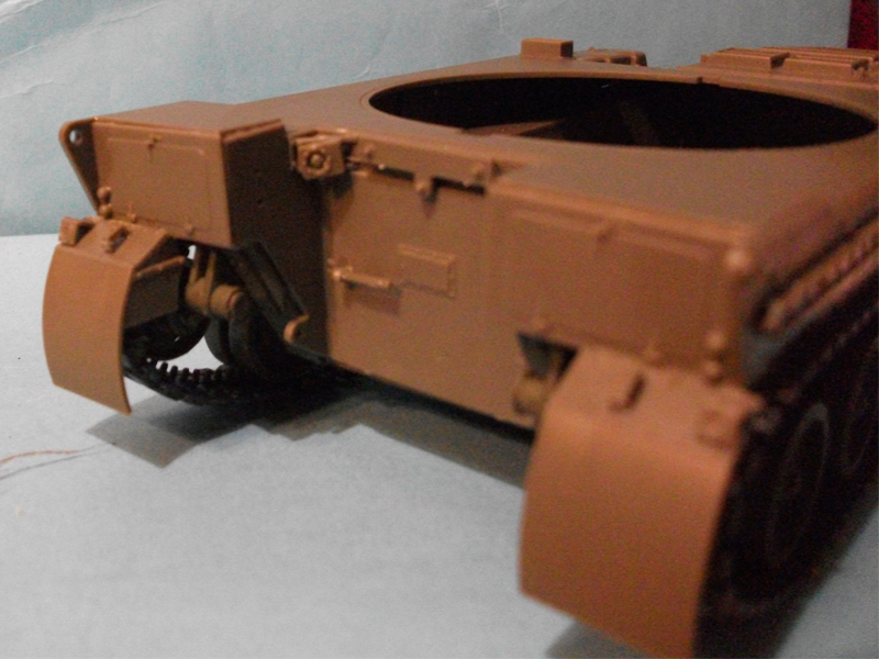
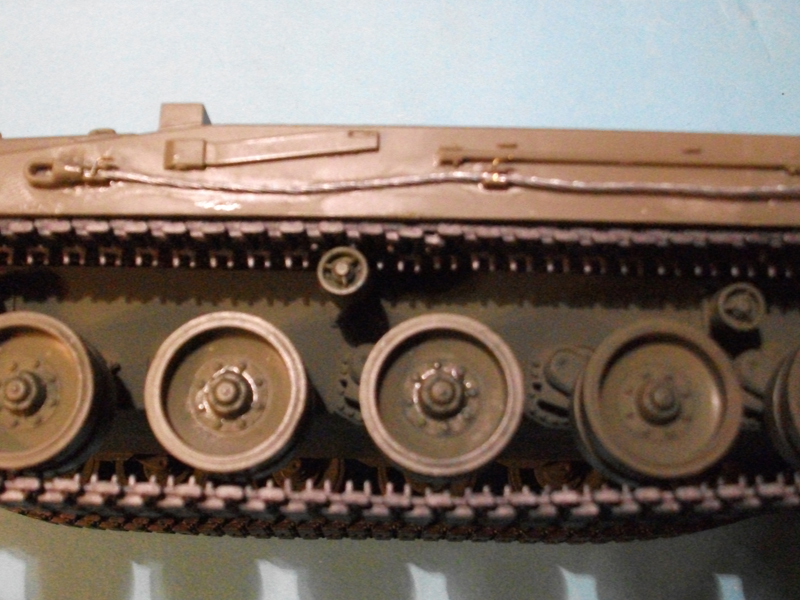
These three stages cover assembly of the suspension, axles, and return rollers. All steps were followed as per the instructions, and no problems or errors were found. There are some light mould seams that require the lightest of scraps with a blade to remove. I did omit attaching the idler wheel axles and tensioners as the exact location for the arms has not been identified. The tensioners and idler wheel axles where attached when the track was assembled, this allowed for a position that keeps the rubber band type track tight as on the real vehicle. The provided picture shows the idler mount in position, which in my case was approximately 90 deg to the sponson.
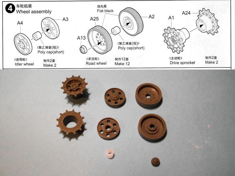
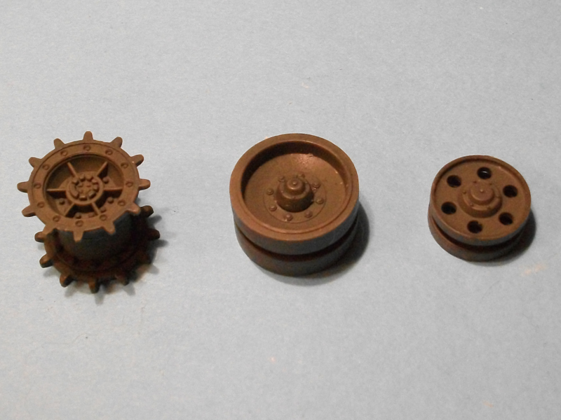
Stage 4:
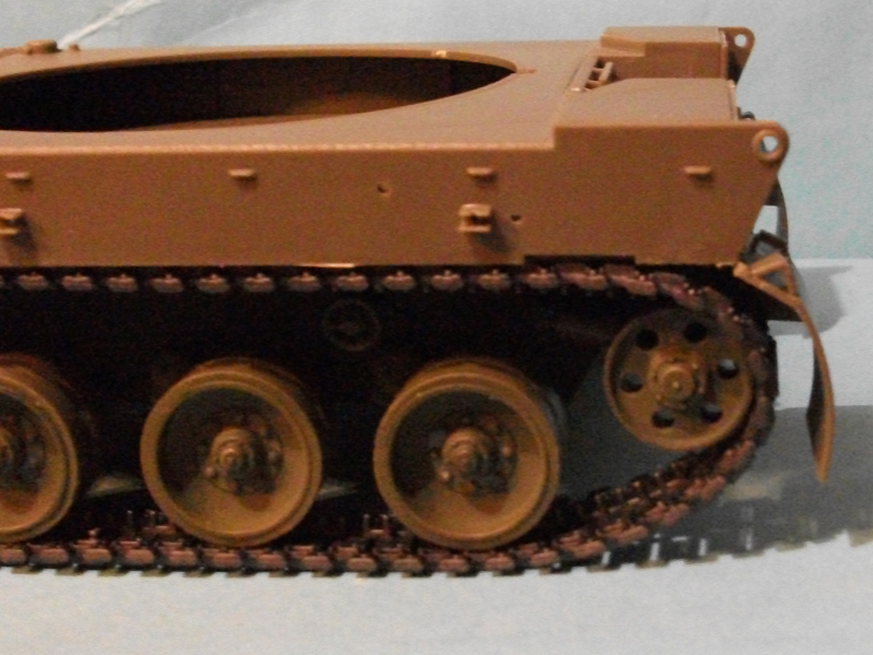
This covers assembly of the drive, idler, and road wheels. With the exception of the drive wheel, the others have followed Tamiyas method of wheel assembly. This involves trapping a poly plug between the two wheel halves, and attaching a plastic cap on the outside of the wheel.
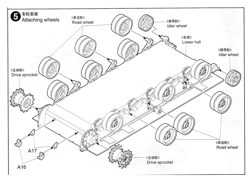
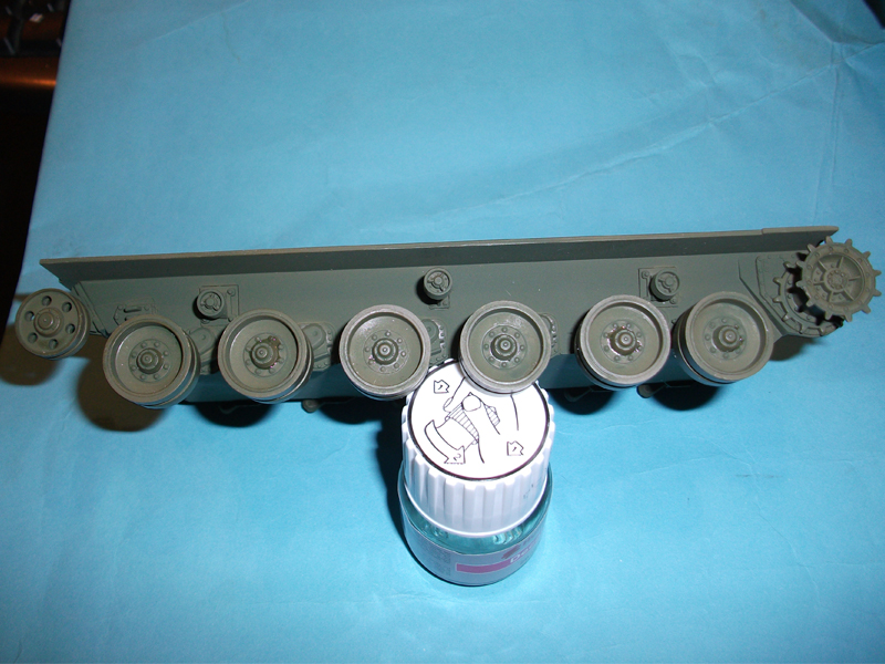
Stage 5:
While I did not do this at this stage, there is nothing to prevent you from attaching the wheels as a temporary measure due to the use of the poly caps (with the exception of the drive wheel). I advise that the wheels are fitted after they and the suspension (everything below the sponsons) is painted, I used Tamiya NATO green XF-67, you can use which ever brand and colour you prefer. Lastly in this stage you attach the towing hooks and mounts. This was fairly straight forward, but I do advise a small amount of the locating lug on the mount is removed to allow a good solid connection to the vehicle. The towing hooks in the instructions are shown fitted upside down, so bear that in mind when securing them.
Stage 6:
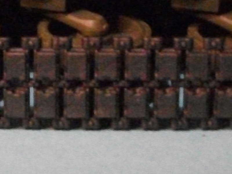
This stage covers assembly of the rubber band tracks, and the two bell housings for the drive wheels. The tracks, considering the media used, are excellent and do not require an after market product, as this would be in my opinion a waste of money. I attached the two ends of the track using a heated nail. I pushed a nail with a small head into a piece of wood which acts as a handle. You then heat the head of the nail slightly over a candle and use that heat to melt the protruding ends of the attachment lugs where they poke through the track. You, of course, can use a method of your choice such as stapled, sewn, or glued. The jointed part of the track in this case was hidden along the top run, this way it cannot be seen due to the skirt. The bell housings do have a mould seam all the way around that will need to be removed, other than that they were easy to attach.
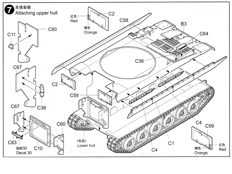
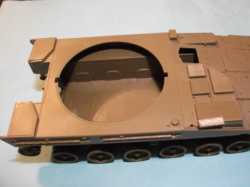
Stage 7:
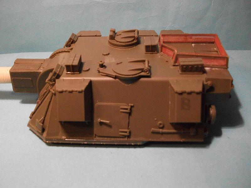
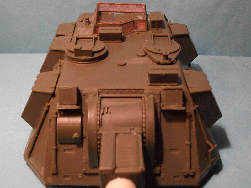
In this stage I got to start the hull and attach it to the tub. When removing the hull from the sprue take EXTRA care with the connection points on the front fenders, I didnt and ended up doing a repair to the left fender as they are particularly finely moulded, and it split leaving a small gap. The hull is a very good fit to the tub and I used Humbrol liquid poly, attaching one side at a time before moving onto the rear panel and hatch. By not following the construction steps by the book I did cause myself some problems and avoided others. The rear panel is a very tight fit where it contacts the hull, so by attaching the hull and then the rear panel I was able to exert some force while locating the parts which made for a very tidy finish, it does however make sliding in the rear panel a very tight fit.
I did not attach the two side skirts at this time as it would have meant permanently placing the tracks on the model, which I wanted to do at a later time after painting had taken place. I also left off the fire extinguisher (which is red in colour), again until after the model had been painted. Part C64 which attaches to the front upper hull had a deep sink mark in it which needed filling, fortunately the sink mark was on a flat surface with no detail and the fix was easy.
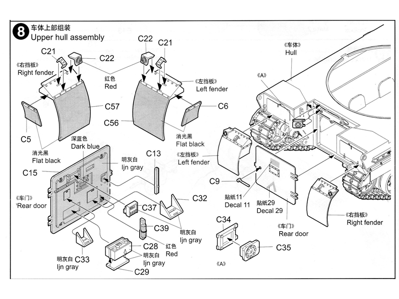
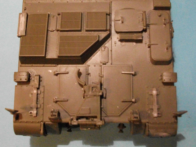
Stage 8:
This covers the rear access hatch and rear mud guards. The rear hatch door does have a lot of detail on the inside face, however as there is no interior at all I decided to forgo using these parts. If you have located an interior for this vehicle, or indeed decide to scratch build one, this door will give you a good viewing area. The omission of all these internal details made attaching the door a quick job. The rear fenders go together easily without any issues. When they were attached to the hull I was not impressed with the connection point as it does not lock the fenders into a set angle.
Stage 9:
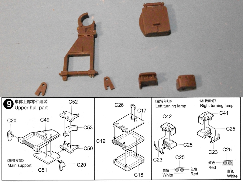
This stage covers three sub assemblies for the model, these being the gun travel lock, the drivers hatch, and the left and right front light clusters. Assembly of these three sub assemblies is straight forward as they are all correctly identified in the instructions, and go together cleanly.
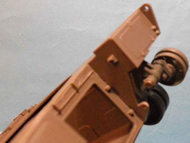
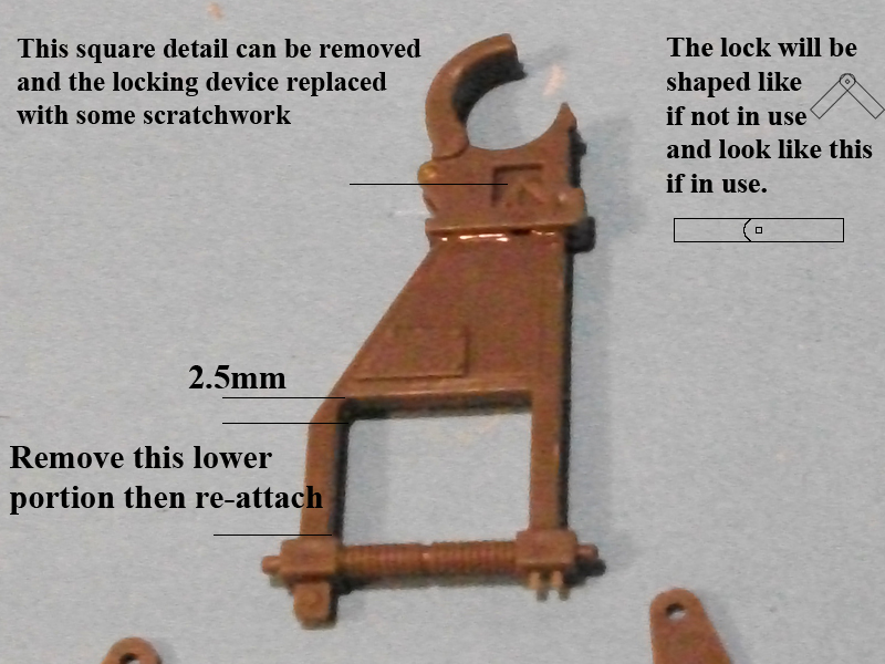
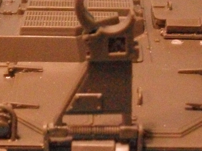
There are some corrections that can be easily made to the travel lock as the kit item is too long. The arms need to be reduced to 2.5mm, that measurement needs to be taken from the clamp end in order to be left with the correct profile. In the picture you can see the portion I removed, I also removed the portion below the right leg.
In the image you will also see a red square. This portion needs to be removed to add to the accuracy and the part in black then needs to be replaced with shaped brass shim or some other material, I did not do this as I noticed the correction after I had cemented the pieces together.
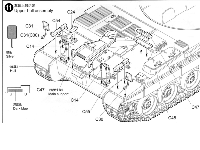
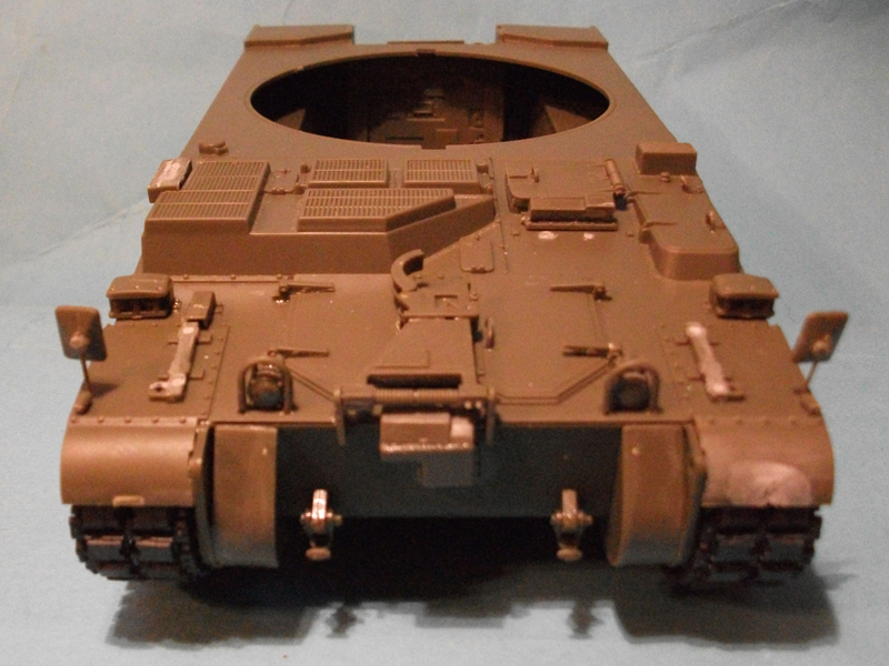
Stages 10 and 11:
These two stages cover final assembly of the hull before moving onto the turret. Stage 10 was followed without any issues arising. The tow cable was fitted, which I prefer to use picture hanging cable as opposed to the provided string. I purchased this cable from a £ shop in the UK and represents excellent value for money, I believe this makes for a much more realistic tow cable. I drilled a 0.7mm hole about 1 mm into the end of each tow cable eye, and then inserted the wire cable and secured with CA glue. The retaining clamps for the tow cable are well moulded onto the side of the hull, but the locking mechanism is not provided. Using 3 pieces of 0.5mm brass rod cut into 5mm lengths and bent at 90 degrees at the mid point, I then secured top to bottom over each of the three retaining brackets.
Stage 11 has a few issues that need to be overcome. Firstly there are two push out marks in parts C54 and C55, these holes will need to be filled before attaching to the model. Parts C48 and C47 need to be moved nearer to the drivers hatch, and part C47 also has a sink mark in its face. All other parts were applied without further issue and the hull is then complete.
During the construction that took place after this stage I managed to break off one of the wing mirrors. This setback was easily overcome and I believe is an improvement on the kit part. After cutting away all remnants of the plastic support arm I drilled a 0.5mm hole in the remaining hull mount, and the rear portion of the mirror. Then using 0.5mm brass rod cut at 15mm and then bent at 90 degrees 5mm in. insert the 5mm end into the vehicle mount and the 10mm into the rear of the mirror. This gives you the added advantage that until glued the mirror can be placed erect or stored.
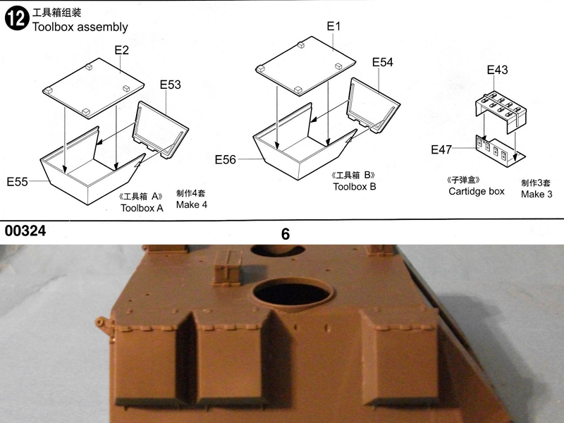
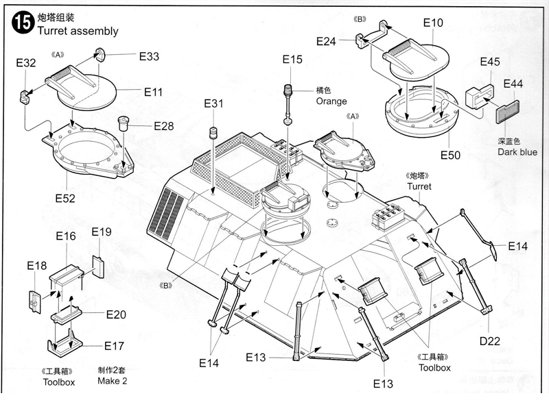
Stage 12:
Here you will assemble the 5 side tool boxes along with the ammo cans for the roof of the turret. All parts went together well without any problems, take care that you get the back panels the correct way up as the pins locate on the turret. Lastly make sure that you can identify toolbox B from the 4 toolbox A assemblies, as there is a very small difference in size (box B is not as wide).
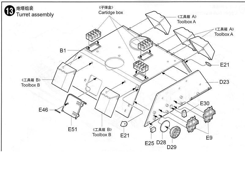
Stage 13:
You will now attach the rear panel of the turret, the tool boxes and ammo cans that you made previously, the side access hatch and some rear panel details. Due to the large size of the turret I had to attach the rear panel in two stages in order to get a good mating of the surfaces. The toolbox locations are incorrect on the left side as it shows two of box B, box B is placed at the rear of the turret and one of the Box As at the front. No other issues arose and construction was followed to the letter with the exception of the spare track links which I left off until painting had been done.
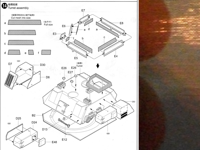
Stage 14:
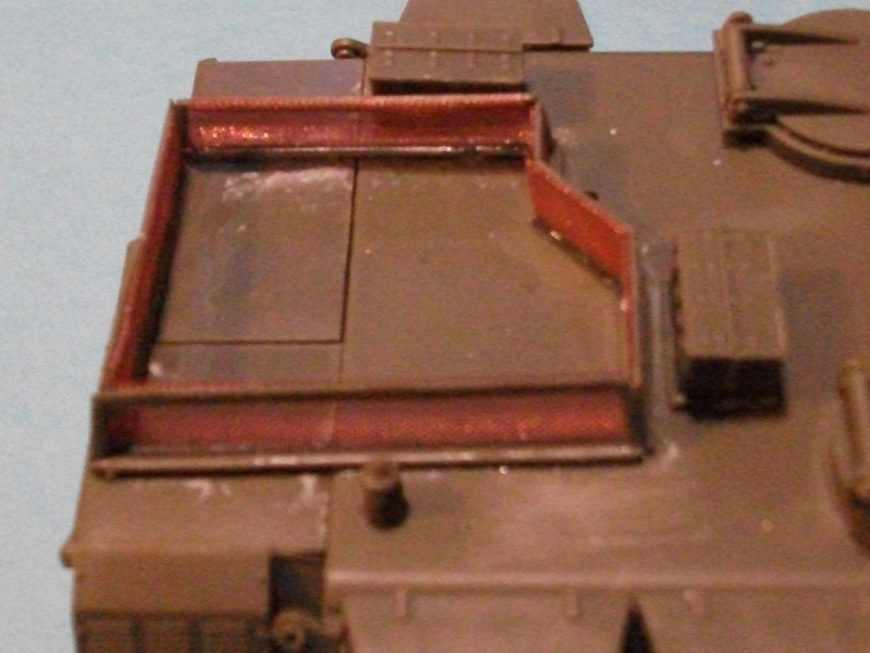
Covers the roof basket behind the commanders copula, and finishing the rear panel. Be very careful when removing the basket frames as a breakage would be difficult to correct, I advise each panel is removed from the sprue and cleaned before removing the inner sprue supports. Trumpeter has supplied nylon netting to simulate the basket mesh, similar to the product Tamiya provides with their kits. I will not be using this as I have purchased a wire mesh from a company called Hobbycraft in the UK. The plans provided for cutting the mesh are slightly too small in height, so you have been warned. Part E4, and E5 are incorrectly identified in the instructions as E4 is E5 and vice versa.
Somewhere in this assembly there is a dimensional error that causes attaching and locating all six pieces to be a real pain. I attached the units to the roof as individual pieces, starting with E8, E5, E4, E7, E3, and finally E6. E6 did need to be trimmed to get even a reasonable join. There are two assemblies for the rear of the turret in this stage, with the larger of the two requiring some forward planning, part D7 does not give you a good fit with D30 and D6. If you are aware of this you can get a good fit to part D30 leaving a small gap where it contacts part D6, this does not matter as it cannot be seen once attached to the turret.
Stage 15:
This stage concentrates on the two copulas and vehicle tool kit. The two copulas appear to be correctly detailed, including the shape of the padded area on the copulas hatches. There is a problem here in that both padded areas have three large push out marks, which gives you three options for correcting the issue. You could just fill the push out marks (the easiest method), a thin layer of putty/filler could be applied over the entire shape and then textured (the method I used), or remove completely by sanding the surface down and starting from scratch using filler or putty.
The tool kit provided is acceptable but nothing to write home about. There are some small improvements that can be scratched here such as the support brackets at the base of the three shovels, and the retaining clamps. The front tool boxes are horrible and one item I regret having attached as the separate support brackets are quite good.
The convoy light is improved greatly by removing the green plastic lens portion, and replacing it using some round profile clear plastic sprue. Just cut the sprue to size and then dip into some yellow food colouring, and then when that has dried dip into some Klear floor polish. I feel that this gives an exceptional look to the part. If you wish you can go further by drilling into the base of the lens, drop in a tiny amount of Klear floor polish, and then insert a small piece of aluminium or steel shim to replicate the reflector.
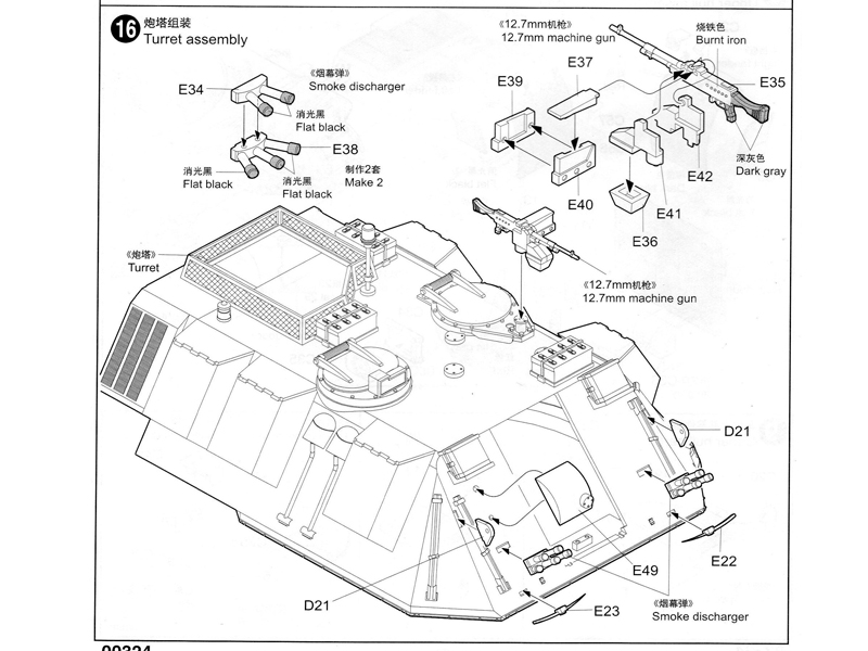
Stage 16:
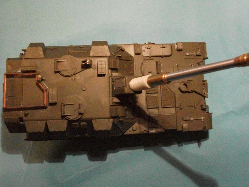
In this stage the defensive weaponry is attached. The 7.62 GPMG (General Purpose Machine Gun) on turret for defence is include and appears to be the accurate weapon, however it is incorrectly identified in the instructions as a 12.7mm MG. Construction of the GPMG mount should not cause anyone problems, and will look acceptable when assembled. The end of the barrel of the weapon needs to hollowed out in order to improve it.
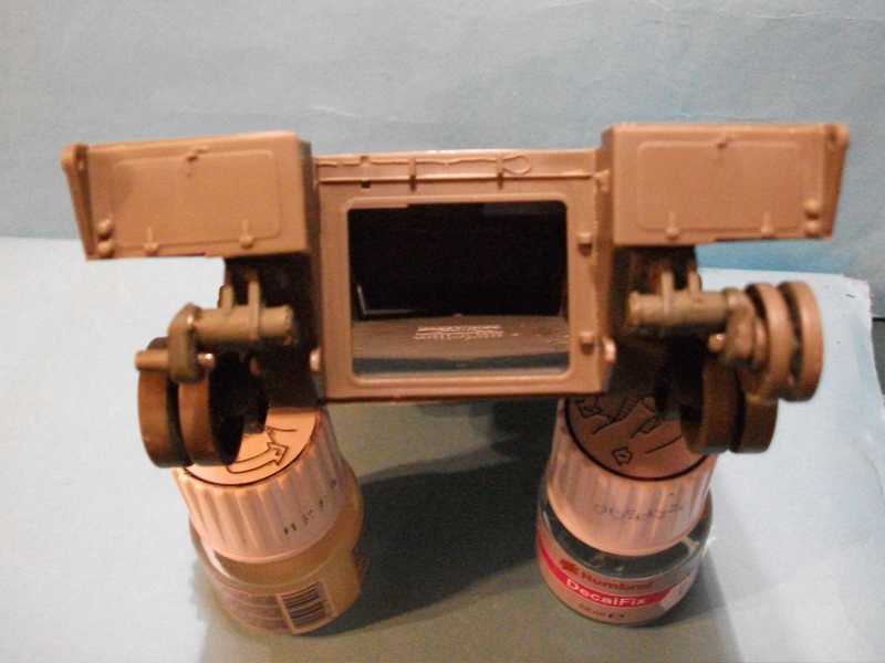
The smoke dischargers, while appearing reasonably acceptable at first glance, are not at the correct angle or on the correctly shaped base plate, and furthermore I believe each tube to be too long. There is no easy or quick fix for this problem and I believe the only way to correct the issue, is to throw them in your spares box and start again from scratch, and if anything will be the hardest part to correct.
Stage 17:
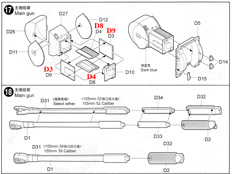
This stage covers assembly of the main weapons breech and locating the breech into the mantlet. The stage consists of 13 parts. Careful application of the adhesive will be needed if you wish the main gun to be able to elevate. In order for the main gun to be able to elevate no adhesive should come into contact with parts D11, D12 and where they attach to parts D26 and D27.
This step has some errors in the instructions. The four pieces that make up the gun breech are 180 degrees out. Part D4 which is shown as the top panel is the bottom panel and vice versa for part D8, part D9 is shown as the right side and is in fact the left side and again vice versa for part D3. The difference in these parts is what I believe to be an inspection hatch replicated on parts D8 and D9. The hatch that can be seen in the instructions (D9) is correctly orientated as regards front and back, and the inspection hatch on D8 should be towards the gun and not the turret.
Locating the breech assembly into the mantlet was complicated by the lug on partD11 being ever so slightly too long, which prevented the part from seating into the mantlet. This is easily corrected once the problem is identified. I should also mention that the correct positioning of parts D11 and D12 is important as they are handed with different sized locating lugs, and not having the same orientation.
Stage 18:
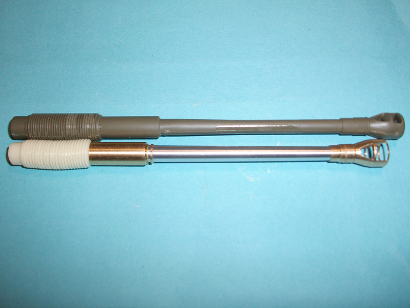
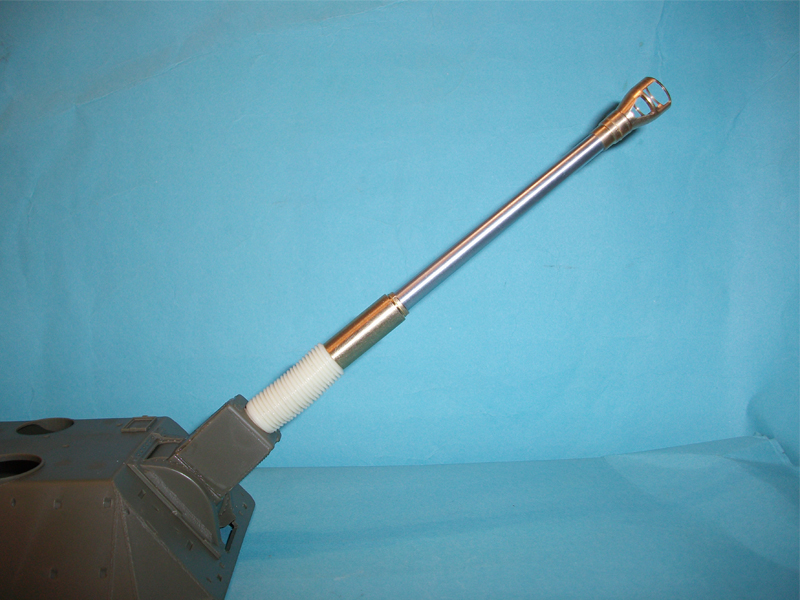
I skipped this stage as I replaced the barrel with a product from JB Model.eu, which is
Reviewed Here on Armorama.
I will mention that assembly of the kits main gun will not cause you any problems. However please remember that the part replicating the recoil cover does have a locating lug for attachment to the breech, this means if you do not pay attention when attaching the main gun to parts D2/3 the muzzle brake will not be in the correct orientation.
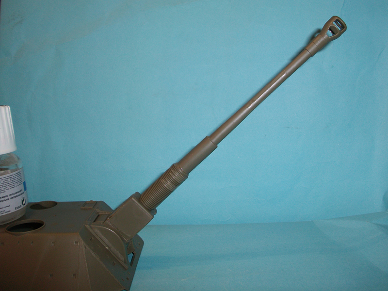
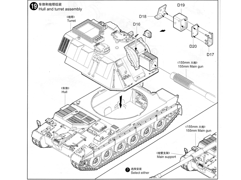
Stage19:
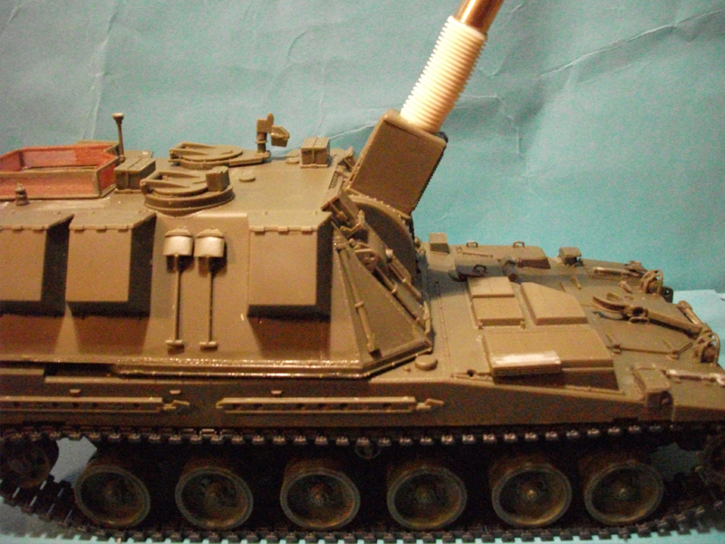
Finally there, as far as construction goes. Attach the barrel to the turret, and locate the turret to the hull. Finally assemble and attach what I believe to be the range finder, and then your model is ready to be painted.
Conclusion
For a model that is one of Trumpeters early kits it has a lot going for it. The weld detail and finesse of some parts is of a very high quality. The model does have some accuracy issues, and the instructions lead you astray in a few places. These minus points do not detract too much from what is a very impressive looking model once complete, and the corrections I have made should be within the ability of most modellers. I will recommend this model with the proviso that you are aware that some work will be needed to improve accuracy, and can be taken a lot further than I have done.


Comments