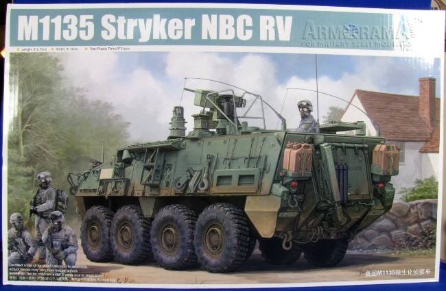
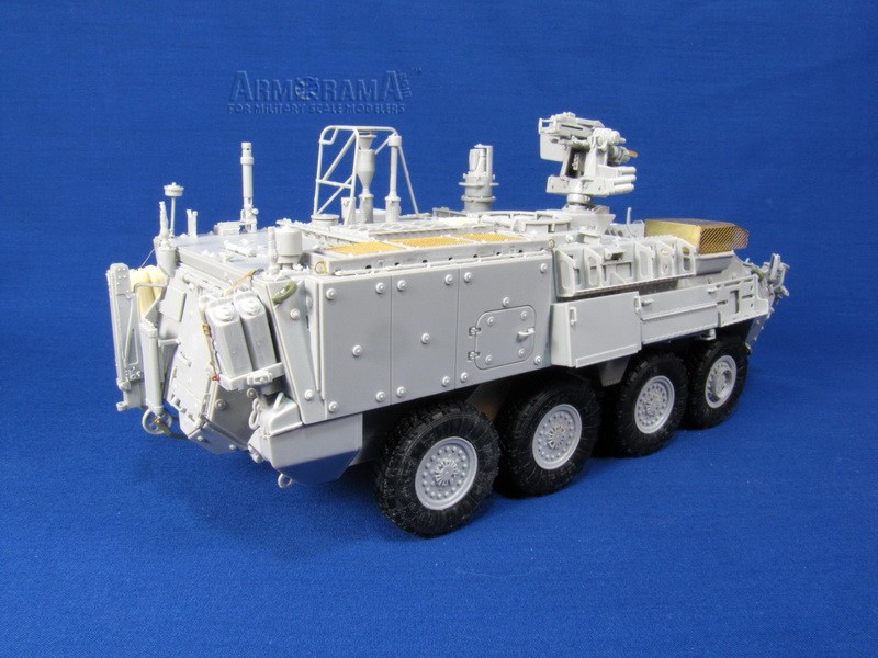
The M1135 Nuclear Biological and Chemical Reconnaissance Vehicle was fielded in 2006 and replaces the M93A1 Fox. It has a crew of four: Driver, Commander and two NBC Surveyors to operate the equipment and take samples. The surveyors can take samples from the air, water and ground and do analysis all from within the safety of the vehicle. Information can then be transmitted to the rest of the SBCT (Stryker Brigade Combat Team) via a Communications suite consisting of: the Single-Channel Ground-to-Air Radio System, the Enhanced Position Location Reporting System, the Force XXI Battle Command Brigade and Below System along with the Global Positioning System. (SINCGARS, EPLRS, FBCB2 and GPS).
For further reading of all the systems and sensors packed into this lab on wheels I highly recommend WWPs Stryker in Detail Part 2 mentioned in the reference at the end of this review.
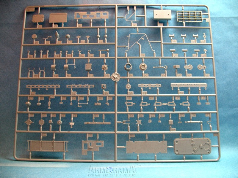
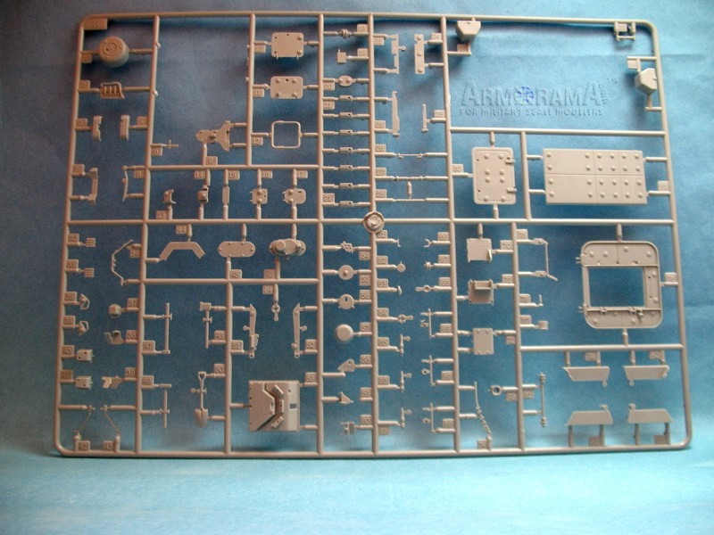
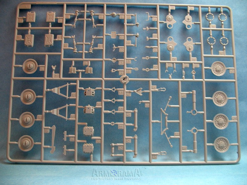
Whats in the box?
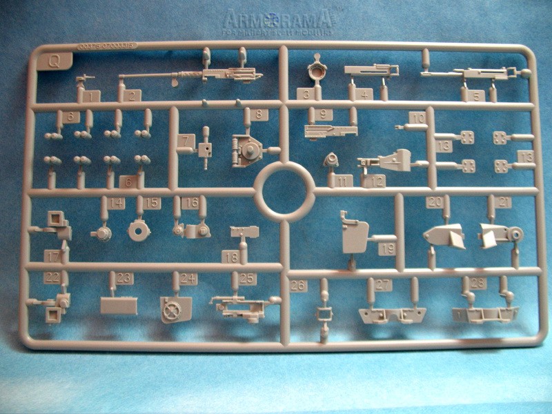
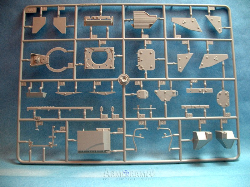
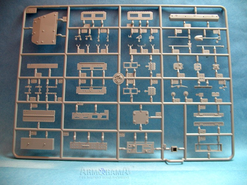
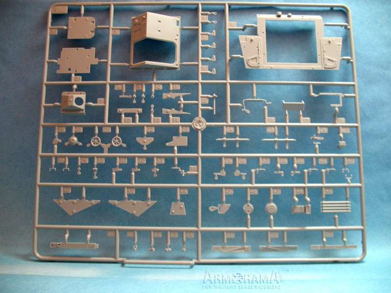
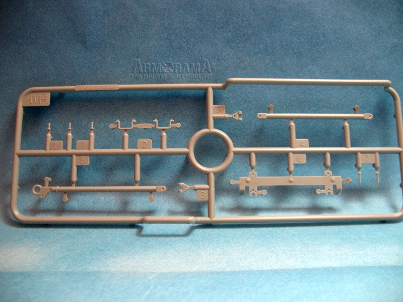
Ten sprues of parts molded in a light grey plastic including:
2 x A sprue,
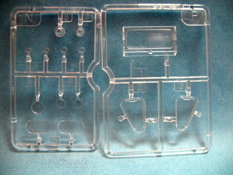
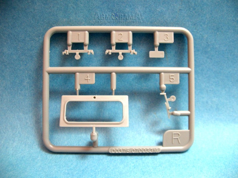
Two small sprues of clear parts,
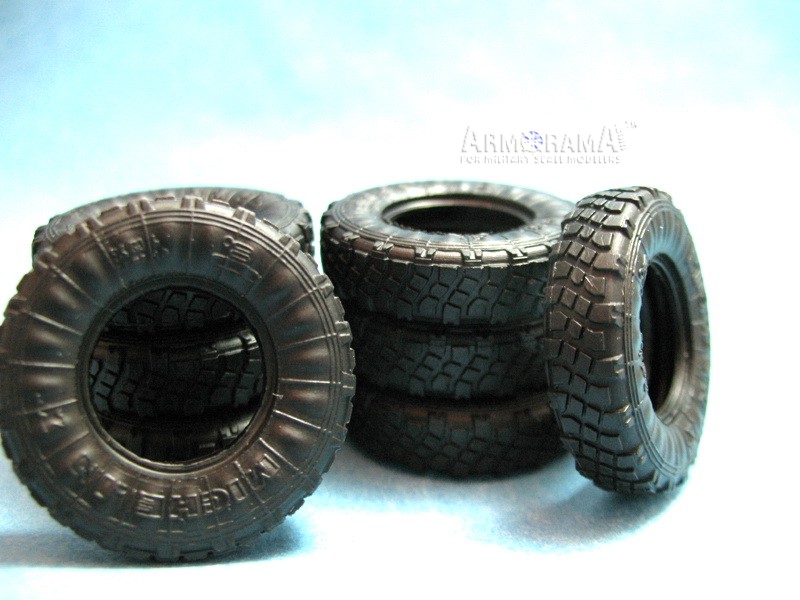
Eight vinyl/rubber tires,
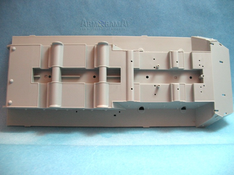
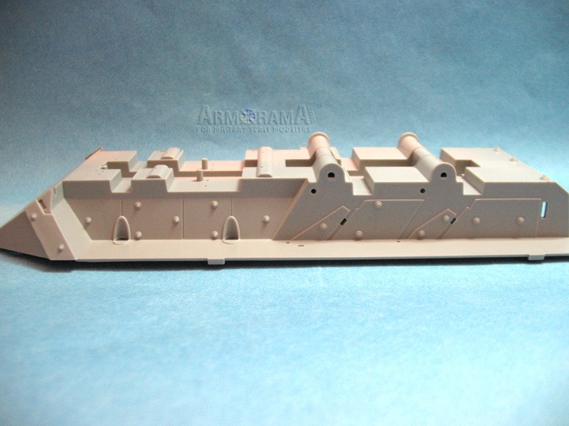
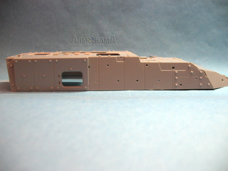
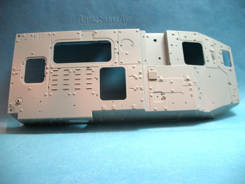
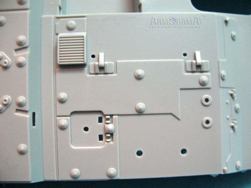
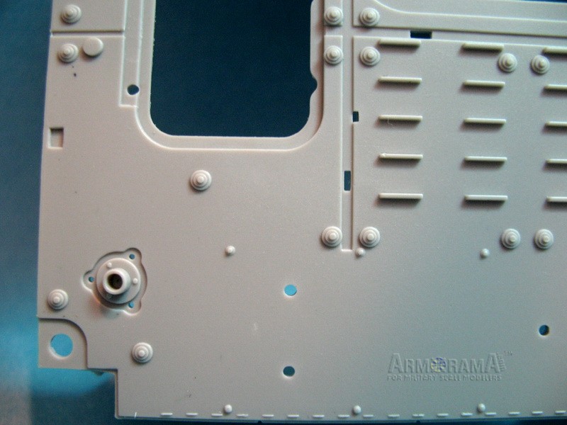
Upper and lower hull parts,
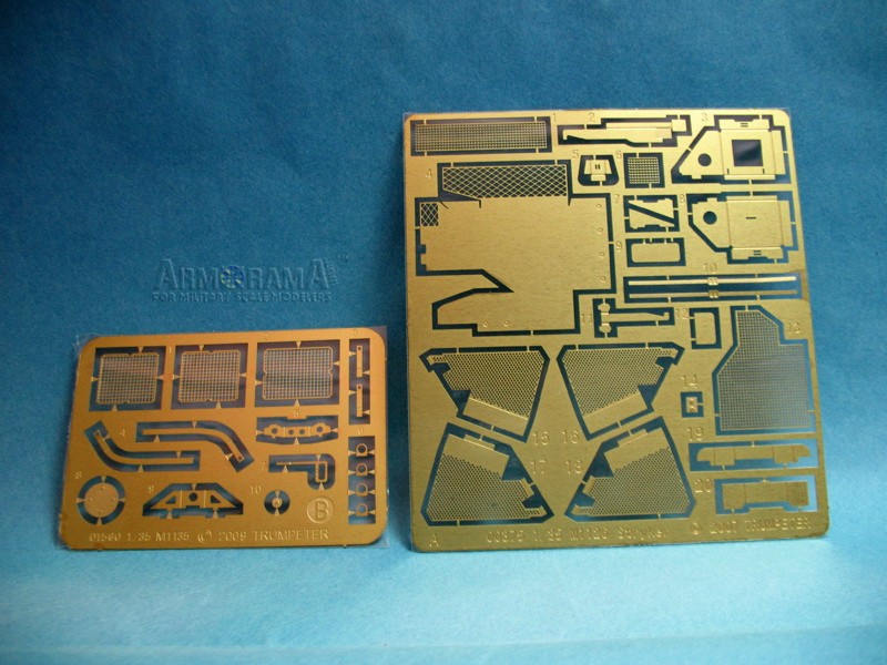
Two small photo-etched brass sheets,
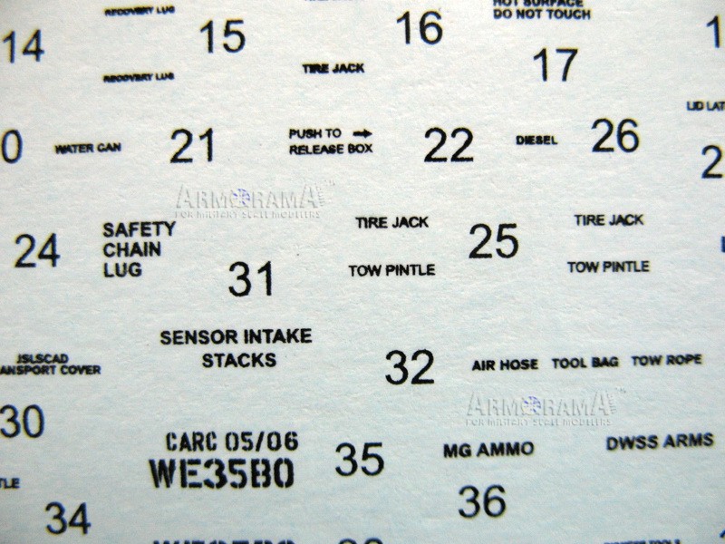
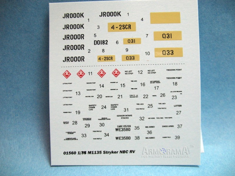
Decal sheet,
Mask material for drivers windscreen clear parts,
16 page instruction sheet,
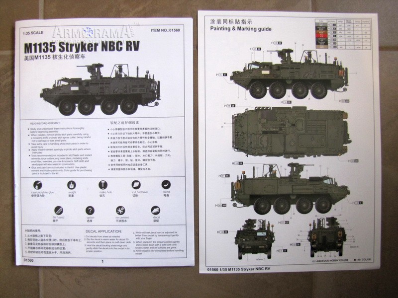
One page paint and marking sheet,
One page advertising supplement.
Curiously it does not contain any other extras that are in some other newer Trumpeter Stryker kits like ration and drink boxes.
The Build
I tend to jump around during construction as I build a model much like the real ones are assembled: I put together the main components first (upper and lower hull parts, rear plate, doors and hatches) then add the detail parts. This is not so much an out of box build as I want to show a few small things that can be done to make an accurate M1135. For the purposes of this review I will follow the instruction sheet sequences.
Step 1: Starts off the build with attachment of the drive train components to the lower hull. The lower front glacis appliqué armor panels are shown added as well. I would advise leaving the end pieces (WC 13 and 14) off until the long tow lug pieces (A33) are attached in step 2 to ensure there is enough clearance for them to fit.
Step 2: The tow lug strips are added as well as the front tie rods. I replaced the A33 lugs with some leftover AFV Club parts as they are more to scale and easier to clean up (the Trumpeter parts had some significant knock-out pin marks in them and seemed a little thick). I also replaced most of the other tow lugs with leftover AFV Club parts as they have a more accurate shape. Take note of the fine print to file off the lower corner armor-mounting bolt as it needs to be flat in later steps.
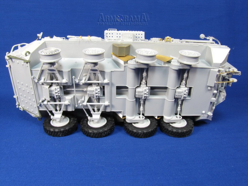
Step 3: Measurements are given here to drill two holes in the bottom lower hull to attach the mount for the DWSS (Double Wheel Sampling System) added in Step 6. However its just as easy to file off the mounting pins on the base of the mount and attach it directly to the lower hull in Step 6. Rear suspension parts are assembled now just pay attention to the orientation of the shocks in relation to the mounts, as you will need two for the left side and two for the right.
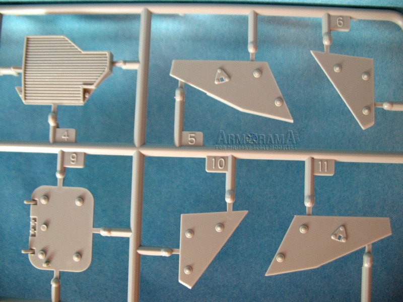
Step 4: Attachment of front suspension components. No real dramas here just pay attention to the part numbers. The assembly only allows for straight ahead steering; it would take a little surgery to turn the front wheels but it is possible. I left the towing clevises off until the painting stage.
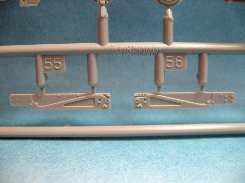
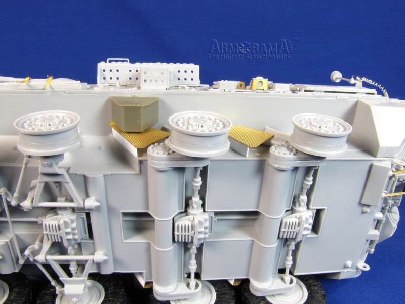
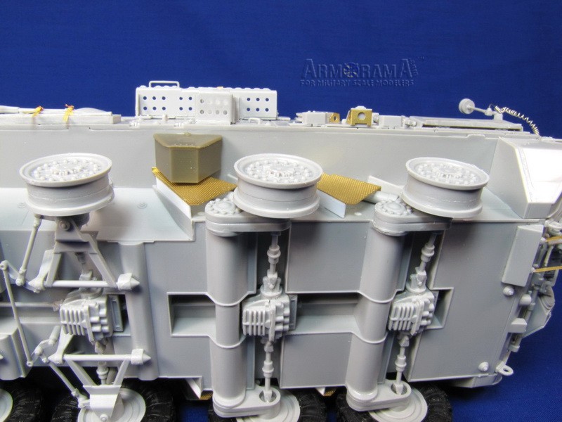
Step 5: Here we move to the attachment of the rear suspension components. Its not really clear but there is an option shown for either the solid shock guards as shown or the perforated photo-etched ones. Really they should have shown just the perforated ones as the solid ones are rarely used on US Strykers. I had some spare AFV Club plastic perforated guards and I thought I could simply attach the nicely molded guards but they dont fit on the Trumpeter hull properly. When you fit the photo-etched guard pieces youll have to attach the solid guards first and then glue to perforated pieces on top of those, which isnt entirely correct. I glued styrene strips to the photo-etched parts and left off the solid guards.
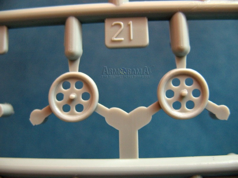
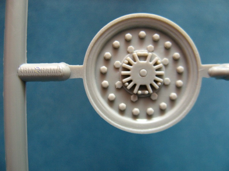
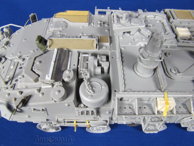
Step 6: This step shows the attachment of the wheels and the small sampling wheels at the back. Its best to leave off the small sampling wheels for now, as inevitably they will get knocked off during the rest of construction. The sampling wheels are about twice the size they should be; which should only be about the circumference of the rear light lenses. The main wheel hubs are OK, but bolt detail is soft. The instructions would have you install the protective rings (A30) on all eight wheel rims but generally only one is seen fitted to the front left wheel to aid climbing onto the vehicle. Missing are the guards for the tire inflation system; these can be sourced from aftermarket wheel sets. I cemented the rims to the wheel mounts so they can be painted with the hull. The vinyl tires slip on easily enough that I will add them later. I also replaced the tire chain bins B84 with the better detailed AFV Club part.
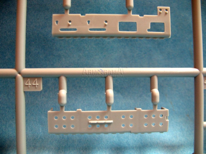
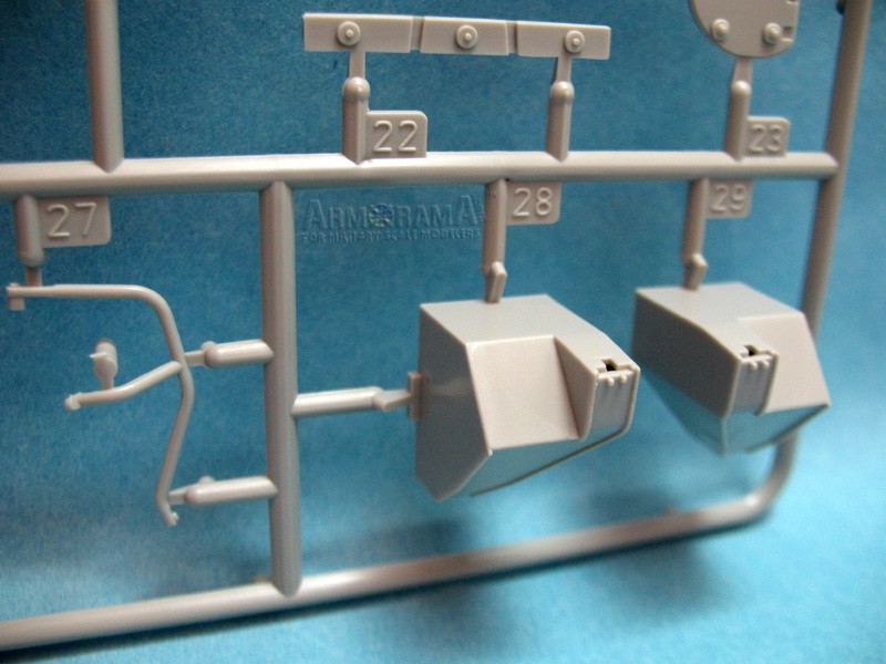
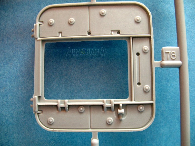
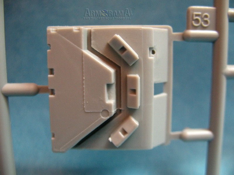
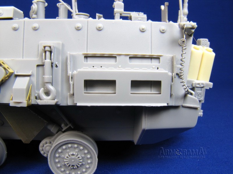
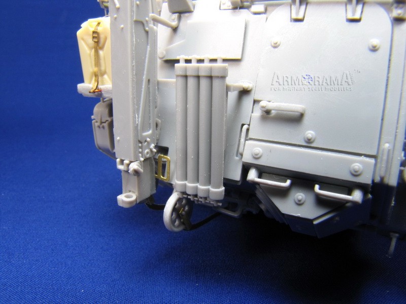
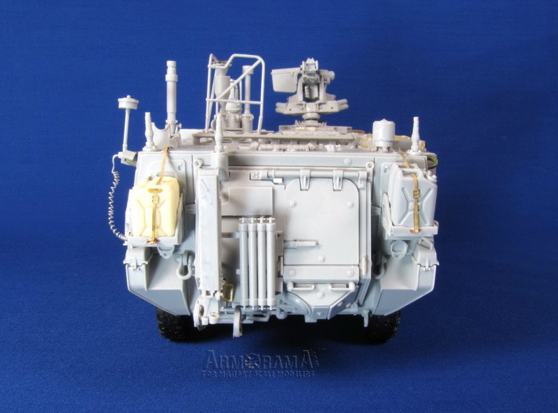
Step 7: This page is devoted to the assembly of the rear hatch. Lots of interesting little bits here, no real fit problems. The rectangular recess on the lower section should actually be an armored glass window; it would have been nice if Trumpeter provided a separate clear part for it. Keeners may want to cut it out and replace it with a clear piece. There should also be another window under the shutter WE23 but nothing is shown. The water cans are OK, but the POL can (Petrol/Oil/Lube) still only has two handles where it should have three. (A problem in every Trumpeter Stryker series kit I believe). I replaced them with resin Voyager items. You could assemble the rear hatch in an open position; there are some bits provided for the interior, but it would just show off an empty interior!
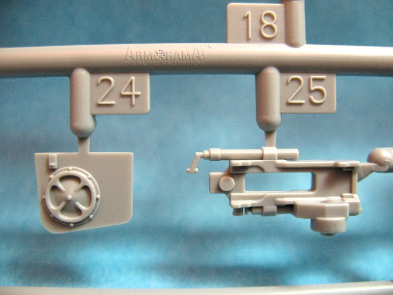
Step 8: Continues with more rear hatch details and rear panel bits. The placement of a small photo-etch part (PE-B7) on the sampling arm mechanism is a little vague, study reference photos for proper placement. Optional photo-etched parts are provided for the jerry-can racks if desired. When installing the clearance lamps (A20) on the racks ensure that they will sit parallel to the ground. There are clear lenses for the tail lights; add these after painting.
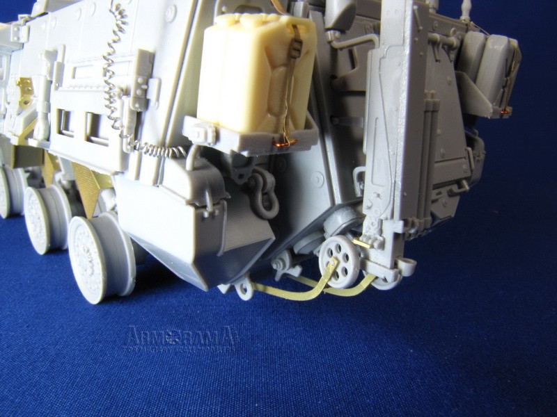
Step 9: Fuel tank assembly and placement and positioning of the rear plate and jerry cans. Even if using the plastic racks it would be advisable to use the photo-etched straps, as the cans would always be strapped in.
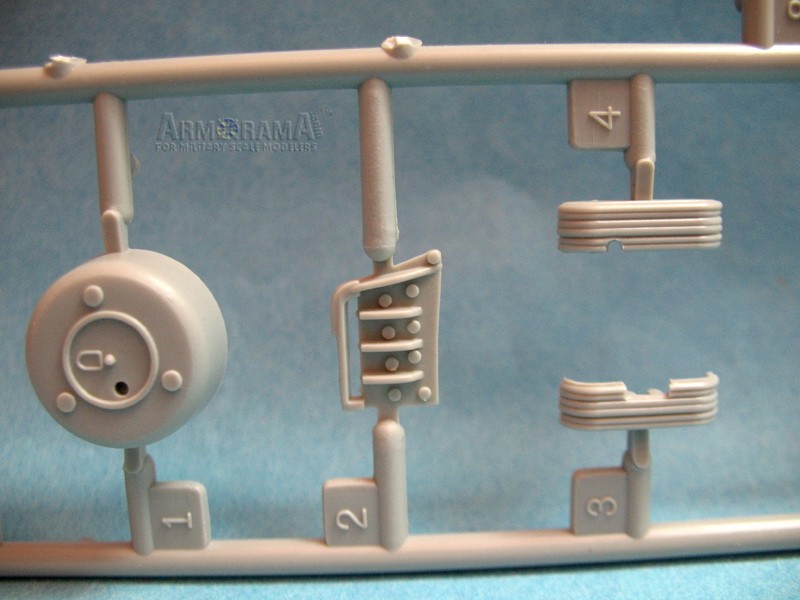
Step 10: Trumpeter calls this the Capstan assembly, which would be the main winch components. Its a basic assembly and it will mostly be hidden by the winch cover. The rest of the step deals with part of the engine deck (intake grill) and front winch fair-lead. There is no cable (string) or cable end provided.
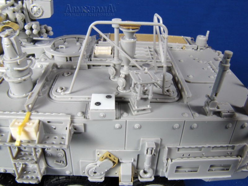
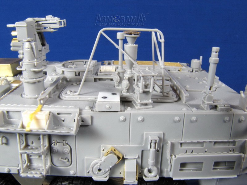
Step 11: Here we start adding detail bits to the upper hull. There is a small latch handle (B61) for the large engine access hatch (WG1) but the opposite side is missing the other latch handle. I used part WC30 which appears to be identical.
Step 12: More upper hull bits. I found it strange that you place a small appliqué armor panel on the right side (WE14) but do not add the back side piece (WE11) until step 23. Might as well do it now so you dont forget it later.
Step 13: Assembly of headlight clusters. The Trumpeter headlight mounts are fairly basic compared to photos of the real ones. Again, clear lenses are provided for the headlights and turn signals; obviously you would want to add these after painting. The front clearance markers (A20) are shown to be angled; again they should be parallel with the ground surface.
Step 14: Addition of small assemblies and some stowage racks to upper hull. Also the winch cable drum and side fair-lead. I have seen photos of some M1135s without the large roof mounted ammo can stowage rack (WF6); but then the small dividers molded on the upper hull should be removed as well. The real front winch fair-lead is mounted on attachment lugs and is spaced a good inch from the hull but on the kit it sits flat against the hull. It is worth noting here that Trumpeter have made an attempt to simulate the many tie-downs (Footman loops) on all the stowage racks.
Step 15: Assembly of Commanders hatch. Trumpeter would have you add a guard? (B5 or optional p.e. part PE-A19) but this seems to be a part possibly used on prototype Strykers only; at any rate it shouldnt be there. I filled in the small mounting slots with .010 styrene squares and filed smooth to match the rail.
Step 16: Part B54 will benefit from some thinning down. Part B26 should not be added and the mounting holes for it should be filled and round mounting bosses added. I used some spare p.e. ones I had.
Step 17: This step includes the assembly of a nice MILES II Combat Vehicle Kill Indicator (parts WF36, WG46, WG23 and 24, WG34 and N7) but the instructions fail to mention that this is an optional part, only fitted when used in training scenarios. If you decide to add this you should add all the MILES sensors and attachment belts to all four sides of the vehicle to be accurate. If you dont use it, assemble WF26 and 46, but leave off WF36 and add a square plate of .030 styrene with two mounting bosses on it. Part B15 is a cover for the older style (and inaccurate) DVE (Drivers Vision Enhancer). I used a leftover AFV Club DVE of the proper style and chiseled/filled the old style off.
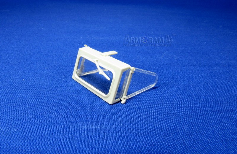
Step 18: Drivers hatch assembly, sensor masts and hatch and drivers foul weather windscreen. I cant comment on the fit or usefulness of the masks for the clear windscreen parts, but there are only masks for one side of the clear parts, which would seem kind of pointless if spraying the entire assembly?
Step 19: There is a small reinforcement bar to the right of the Commanders hatch (WG10) that is easy to miss in this step (ask me how I know!).
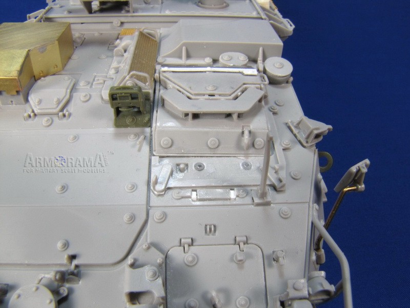
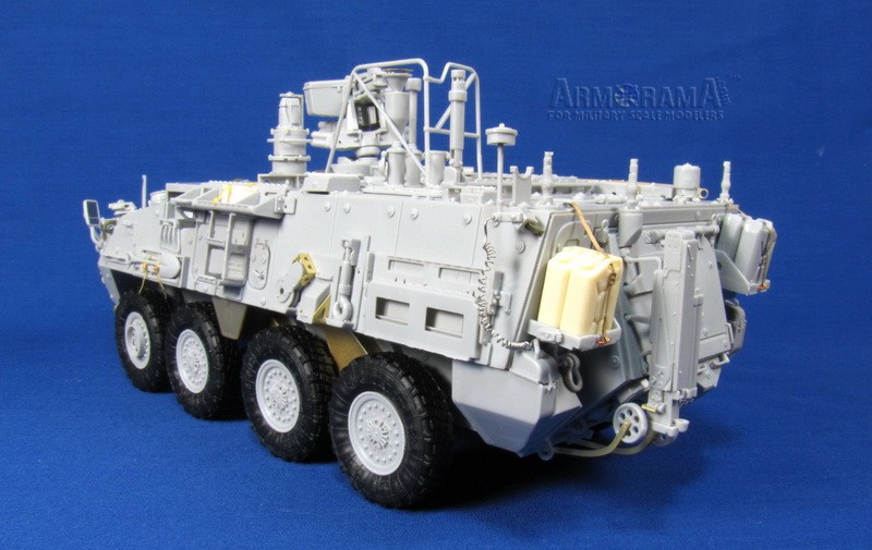
Step 20: Lots going on in this step, the last tool (shovel) is added to the rack and it wouldnt hurt to add some straps as we dont want to be teased for magnetic tool syndrome do we? The attachment of the folding arms on the rear left rack is a little vague; I have included a photo showing proper placement which involves some filing down of parts WG5 to fit. This rack could also be assembled in a down position if desired. The rear amber warning light appears to be fairly common so I added it and added some coiled lead wire for a conduit.
Step 21: The drivers hatch is added here, there is no foul weather cover for the hatch provided so I made one from lead foil and strips of styrene.
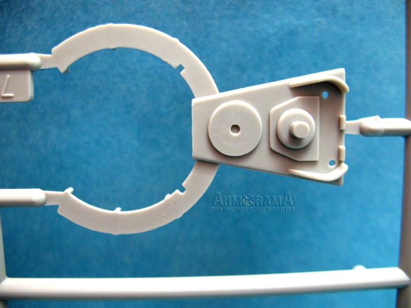
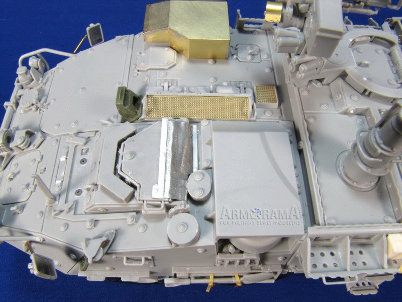
Step 22: Tow bar and mount assembly. The large sensor mast you also assemble in this step is the scanner module for something called the JSLSCAD (Joint Services Lightweight Standoff Chemical Agent Detector). Hows that for a mouthful!
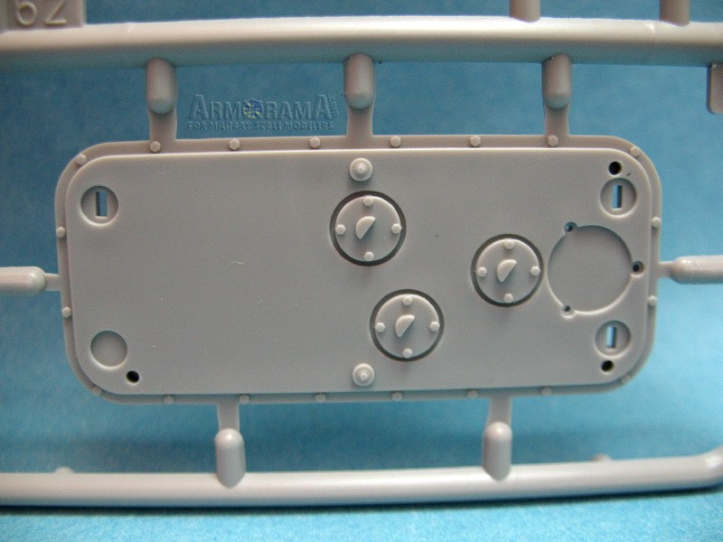
Step 23: The protective guard for the sensor array is assembled from three parts. For molding reasons I suppose the back part is made from two pieces but the lower part is molded thicker and doesnt fit very well. I would suggest attaching WF8 first to WF4 and allow to dry, making sure the joint is straight (a job for superglue perhaps). Then attach it to WF18 and attach to hull when dry.
Step 24: Assembly of upper and lower hull and front bumper piece. Something which most seasoned modelers would have done first!
Step 25: An optional p.e. brass exhaust guard is provided; I soldered mine as its good practice but superglue would work as well for such a simple piece. I think the shape is off a little as it doesnt seem to overhang the exhaust as much as it should. The headlight brush guards seem too thick and out of scale to my eye. Missing is the large horn beside the left headlight cluster seen on most current Strykers.
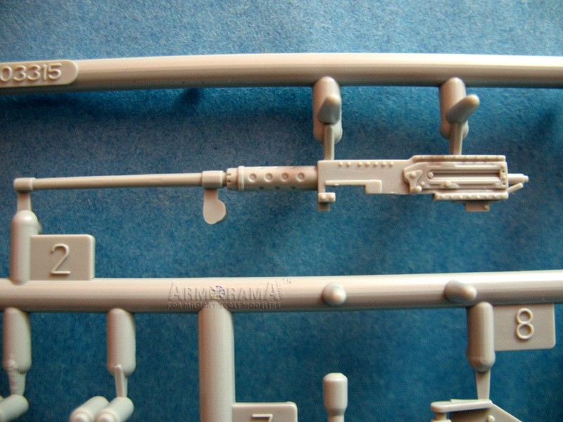
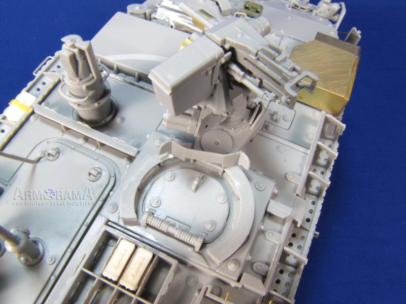
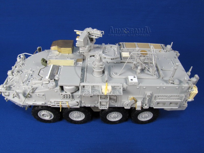
Step 26: OWS (Overhead Weapon Station) assembly. This is the newer, retooled version and provides the option of an M2 .50 caliber or 40mm grenade launcher. Better than Trumpeters first abysmal OWS provided in the original M1126 Stryker but not quite as good as AFV Clubs version.
Step 27: Final assembly addition of OWS, tow bar and rear view mirrors. I replaced the mirror arms with brass wire so I could pose them into a more realistic position. Also some leftover p.e. mirrors were used.
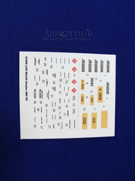
The decal sheet contains marking for two vehicles of the Second Stryker Calvary RegimentQ31 and Q33 both featured in the WWP book.
Conclusion
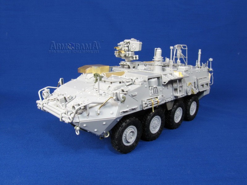
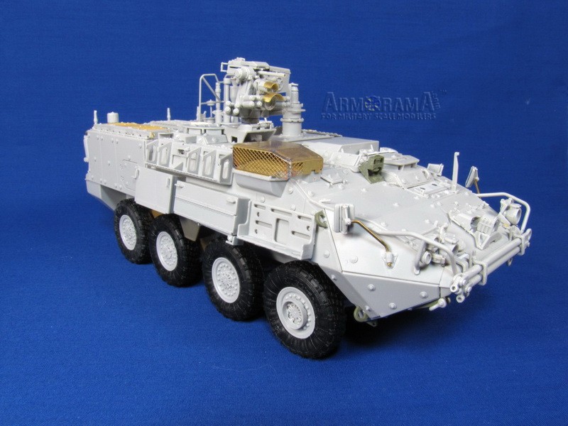
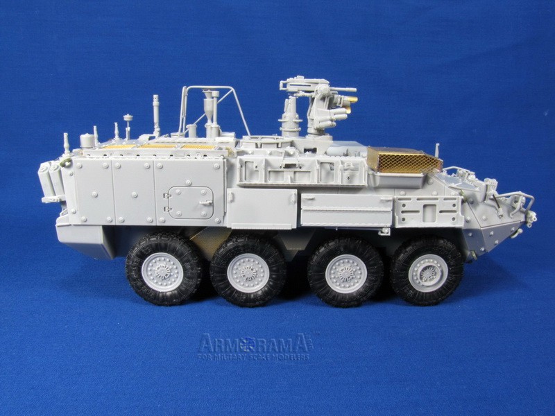
Despite a couple little accuracy details the kit build up into a good representation of the M1135 NBCRV. If Trumpeter would pay attention and correct a few details it would change the kit from a good one into an above average one; the small things like proper DVE placement, addition of the horn, tire self inflation system guards, and drivers hatch weather guard. All things that can be observed with a quick browse on the Internet. But then, to me, thats half the fun of making a model building an accurate representation of the real thing, and if the kit falls short fix it yourself! It is definitely a unique version with a very sci-fi look to it and I look forward to Trumpeters next Stryker, the M1129 Mortar Carrier.
SUMMARY
Highs: Stowage racks, bins and numerous items unique to the NBC-RV variant appear to be accurate and in proper places. Fit of parts is generally very good.Lows: Old style DVE still shown, no horn, some confusion regarding optional parts. Stowage racks a little thick.Verdict: Despite a couple little accuracy details the kit build up into a good representation of the M1135 NBCRV. It is definitely a unique version with a very sci-fi look to it.
About Jim Carswell (junglejim) FROM: ALBERTA, CANADA
52 yrs old, School Bus driver. Been modeling for as long as I can remember. More recently armour, started out mostly with 1/72 a/c (still have a big unbuilt collection).
Have done masters for Maple Leaf Models as well as the now oldish HobbyFan Cougar AVGP. Former Editor of IPMS Edmonton's newslett...
Very nice review indeed. Trumpeter does seem to have problems gettin gsome of the details right. I might point out that my Stryker CD does cover this variant, and with well over 1000 images, it is still the best deal around.
Jim, great review. Picked this out as soon as it came out as I was in the Chemical Corps from 93 to 01.
Re your comment in the review: Curiously it does not contain any other extras that are in some other newer Trumpeter Stryker kits like ration and drink boxes.
Operating in an NBC environment, nothing would be stowed outside the vehicle that could not be decontaminated or would lead to exposure to the NBC specialists. Everything would be inside the vehicle, buttoned-up tight.


Comments