


1⁄35M4A3E8 'Thunderbolt'
11
Comments

Introduction
In general I followed the steps set out in Dragon’s instructions except where it would make painting difficult. There are a couple of omissions from the instructions that I have drawn attention to, and one misleading illustration that I have corrected. The suspension is a bit fiddly but the rest of the build is straightforward enough.The Suspension
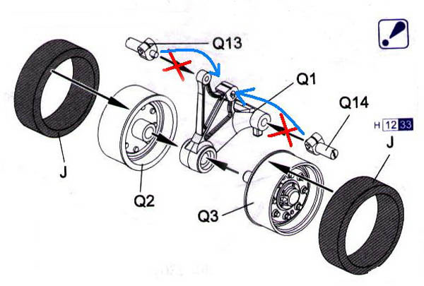
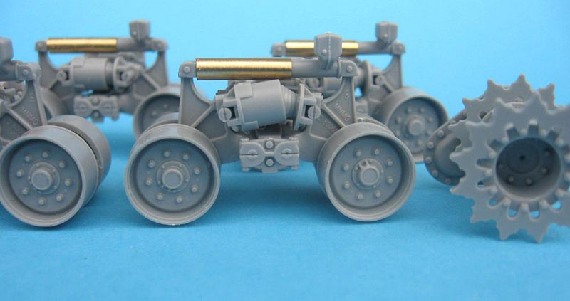
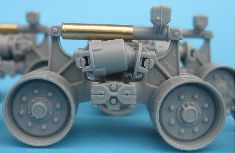
I followed the assembly steps set out in the kit instructions so we begin with the suspension. The idler wheels and the drive sprockets go together simply. The kit offers a choice of fancy or plain sprockets and for Thunderbolt VII use the fancy sprocket part Q28.Each bogey is made up of 28 separate parts and my advice is to read the instructions and dry fit each sub assembly. There are four sub assemblies to be made up for each suspension unit and I recommend letting the cement on these dry thoroughly before putting the suspension together. The instructions are unclear about the construction of the bogey arm and where to attach parts Q13 and Q14 to Q1 so I have included a corrected scan to help the unwary. I would also advise modellers to print out a couple of pics of a HVSS suspension unit from Tanxheaven or another site to refer to during the build.
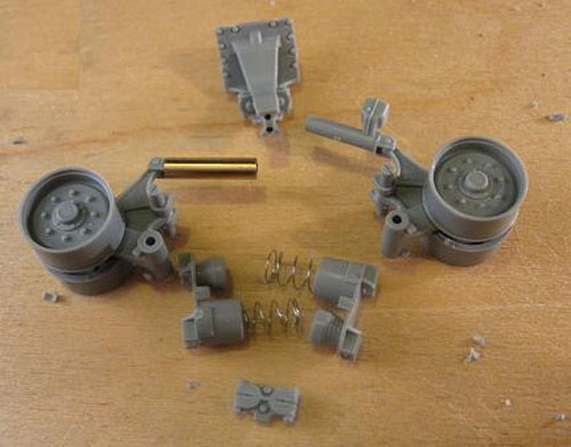
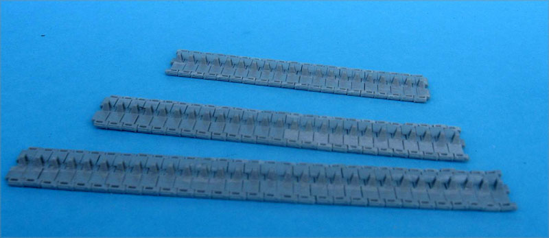
The suspension when built is workable but the tracks are not, which is puzzling, I suppose if you wanted to portray the tank crossing rough terrain you could make the suspension conform to the terrain and then glue it in place. Beware! Real springs (part MB2) are included to mimic the action of the Horizontal Volute springs. The instructions say not to glue them in place and I didn’t. This resulted in a few hair-raising moments when two of the springs launched into space. Thankfully my eyesight was good enough to track their trajectory but be careful, - there are no spares. The next time I build this kit I will put a drop of CA glue on one end of the spring when adding it to part Q4.
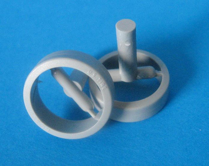
The sprue attachment points are on the rear of the wheels and are hidden when the suspension is assembled which is a nice touch. I left the tyres off to paint separately.
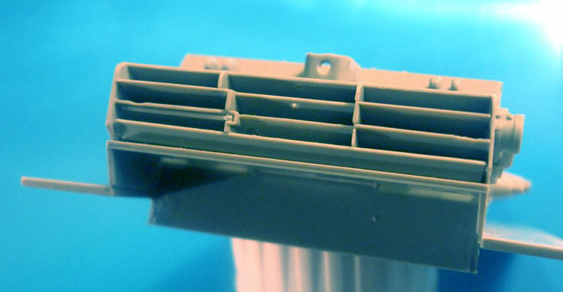
Step one of the instructions also includes the exhaust deflector, which is a really subtle piece of plastic engineering made up of six pieces and really looks the part when assembled. The late war deflector is also included in the kit but marked not to be used and really shows the advances in plastic as it is really heavy and would require a lot of thinning if you wanted to use it. There are knockout marks on the pieces that make up the deflector but these are hidden when it’s assembled so I didn’t bother cleaning them up.
LOWER HULL
Step two shows the assembly of the lower hull and this goes together without any problems. I left the idler mounts part Q31 off until I was fitting the tracks.I skipped most of step four - the fitting of the suspension to the lower hull, until I had the suspension and lower hull painted and only fitted part B35 (which is I think the exhaust for the generator) to the lower hull.
UPPER HULL
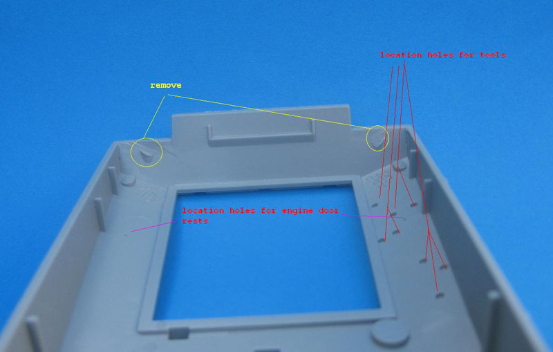
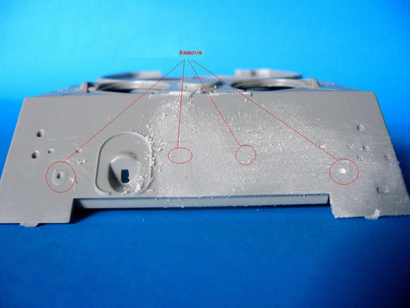
Step 5 and 6 show the fitting out of the upper hull. The first thing that needs to be done is the removal of the grouser box covers, which are a hangover from the M4A2 kit. These should be shaved off and the area sanded flush with the hull. The sanding needs to be done carefully so as not to ruin the raised weld beads on the hull edge. There are also two big chunks of plastic to be removed from the inside of the lower hull. I took these off with a razor saw. On the rear upper hull plate the location points for the spare track holders (Absent on HVSS tanks) are still there and need to be filled.As I was building the kit as Thunderbolt VII I had to shave off the travel lock attachments and the headlight mounts on the front glacis to let me fit the add on armour. I shaved these off with a sharp no 11 blade. No need to be careful sanding these down as they area will be covered with the add-on armour.
A nice feature of this kit is that the tool location points are not marked on the outside but need to be drilled though from the inside if you are using them. I had intended to use the kit tools but broke the sledgehammer when removing it from the sprue so I replaced it with one from the Formations Sherman tool set. Then, as I had it out, I decided to replace the rest of the tools as well. For the first time in plastic we also get the rectangular engine door stops (part A61 & A62) and the location holes for these need to be drilled from the inside also.
There is an omission in the step showing the subassembly of the hull hatches which leaves out part A16 the periscope cover which is marked not to be used on the sprue layout but this is, I think, a mistake. The covers, A16, should be glued to the top of part C1, the periscope, after C1 is attached to part A12. The hatch handles are simplified and I shaved them off and replaced them with handles made from wire.
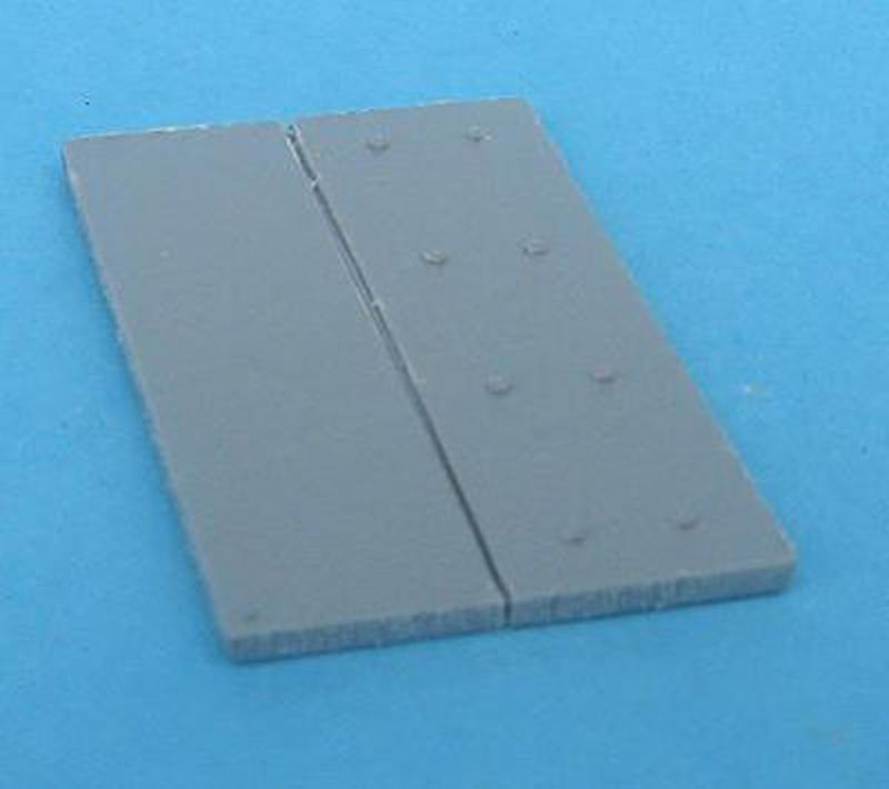
Step 7 & 8 shows the attachment of the etched brass fenders and the add on armour to the upper hull front. This add on armour was cut from the hulls of destroyed Sherman and so came complete with gun travel lock headlights and siren. Part D5 comes with a textured edge representing the torch cut edge of the original steel armour. There is a seam line in the cut out area that fits over the hull machine gun and I got rid of this by roughing up the edges of the part with a razor saw. Thunderbolt VII’s siren was attached just between the driver and the gun travel lock, and not in its correct place on the lower right of the add on armour - so I filled the attachment point and moved the siren up. The siren brush guard I put in its normal position. No etched parts are offered in the kit for the headlight or siren brush guards. In the past I have made these brush guards from flattened copper wire soldered together but on this occasion I used the kit parts.
I don’t have any etch bending tool so I bent the fenders into shape by sandwiching them between two steel rulers and bending the edge against a flat surface. This wasn’t entirely successful but photos show the fenders on Thunderbolt VII as very beat up so I didn’t worry about it too much. The front fenders (Ma3 & MA4) should not be fitted now as the tab on the fender is too large and if fitted will not allow the upper and lower hull to be mated. So you can either wait until the lower and upper hulls are together or cut part of the tab away. This is what I did, using a sharp scissors.
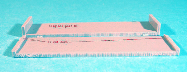
Part D1 the side armour is shown in the instructions fitted over the fender braces (part Q30) but any photos I’ve seen show the braces cut down and attached to the outside of the armour. This is not an option with the kit part as D1 when in place extends to the edge of the fender. A rear view of Thunderbolt VII in Steve Zaloga’s Sherman at War 2 shows the armour as roughly half the width of the fenders and so I cut it back and also roughened the edges with the razor saw. I placed the fender braces according to the photos of Thunderbolt VII that I have and cut the ones over the armour to fit.
About the Author

FROM: DUBLIN, IRELAND
I served three years in the Irish Army. Then I studied fine art for five years. Acted professionally since leaving college (Look me up on IMDB- Pat McGrathIII) Interested in Allied Armour 1942-45 and German SPGs. Other interests are figures and Sci Fi models
Comments

The Split hatch could revolve so the MG could be at the front too. I have a screen grab from a History Channel documentary that shows the .50 in this position which I can send you if you pm me your email.
It also shows the fender braces over then armour. The other references I used were the photos of Thunderbolt VII on page 59 of Sherman at War (2) one of which is taken from the rear and shows the side armour having about half the depth of the fender.
SEP 15, 2006 - 02:17 PM

That coupola makes sense. Then the mount could be swiveled around so the gun sits on its resting bracket like the kit shows. How the heck did you stand in the hatch and fire it without leaning as far back as possible? I did the amor as the kit has it. The refferences are so hard to come by for this tank and I am not really a Sherman fan so I have never bought any literature on it for the only one I'll probably build. After 7 Thunderbolts I guess Abrams never really felt the need to take a bunch of pictures of it I was going to trim the armor away from the braces like the box art but the colorplate showed otherwise.
I guess it will just stay as it is at this point. Even the typical refferences seemed to be at odds with each other I just gave up and started building for the Aces campaign as I have bigger fish to fry and need this done asap.
SEP 15, 2006 - 09:56 PM

Hi Pat,
Thanks for a very useful and indepth review.
Lovely build sir.
Cheers
Al
SEP 15, 2006 - 10:31 PM
To not start another T7 thread-I am now finishing the tracks which are the all steel version from the kit. How rusty should these suckas be? They are in base coat gunmetal now. I was thinking only a minor mottling overcoat with rust, a black sludge wash, then steel drybrushing the contact points. The tank is going to be in pretty fair condition.
And thanks for the heads up Pat! Its a little late for me to alter anything, but the info you have is super helpful for anyone not started yet! I keep seing the mythbusters 'confirmed' armor 'plate' in my head now :-)
SEP 16, 2006 - 07:30 AM
How much rust?
Oh no I don't want the anti rust police after me. :-)
It's up to you and what surface your tank is on. On a hard surface like a paved road in dry weather not much rust, in a wet field then sure rust and mud but how much is up to you.
SEP 17, 2006 - 05:24 PM

Pat,
Thanks for your great work on the Thunderbolt.
I just want to ask. What references can I source out aside from S. Zaloga's M4 Sherman at war (2) to get more pics of the thunderbolt?
Also, are the added armor given the same color as the tank's body or are the weld cuts discoloration visible under the paint? Any take on that?
Thanks again.
Ed
SEP 30, 2006 - 03:29 AM
Hi Edmund
There is some footage of Thunderbolt VII in some of the History Channelo videos - sorry I don't know which ones.
I don't know of any other books containing different photos of Thunderbolt VII than the ones in Sherman at War (2)
If you click on the my photos button at the bottom of this post there are some screen grabs of Thunderbolt I was sent. I can't see any discolouration on the welds. My impression is that when the armour was added on the whole tank got a new coat of paint. I think they would have paid special attention to the welds as they rust very fast if not protected by paint.
SEP 30, 2006 - 04:58 AM

Thanks Pat for a well written interesting log of your build as I dont know much about Shermans, I think that the final result is excellent.
John
SEP 30, 2006 - 05:23 AM
Thank very much Pat. I'll look for those videos and will check your screen grabs.
I already made one uparmored M4A3E8 modified from the DML 1/35 Korean War kit. I'll post it one of these days.
regards.
Edmund
SEP 30, 2006 - 08:02 AM
Copyright ©2021 by Pat McGrath. Images and/or videos also by copyright holder unless otherwise noted. The views and opinions expressed herein are solely the views and opinions of the authors and/or contributors to this Web site and do not necessarily represent the views and/or opinions of Armorama, KitMaker Network, or Silver Star Enterrpises. All rights reserved. Originally published on: 2006-09-15 00:00:00. Unique Reads: 31203

WEB HOSTING BY


Copyright ©2021 Armorama and Kitmaker Network, a subsidiary of Silver Star Enterprises
All Rights Reserved. Please read our Conditions of Use and Privacy Policy.
All Rights Reserved. Please read our Conditions of Use and Privacy Policy.