

1⁄35Building the DML M2A1 Halftrack
95
Comments
bodywork
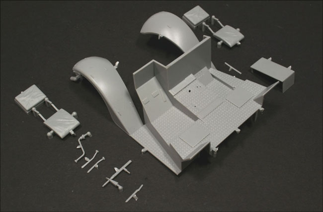
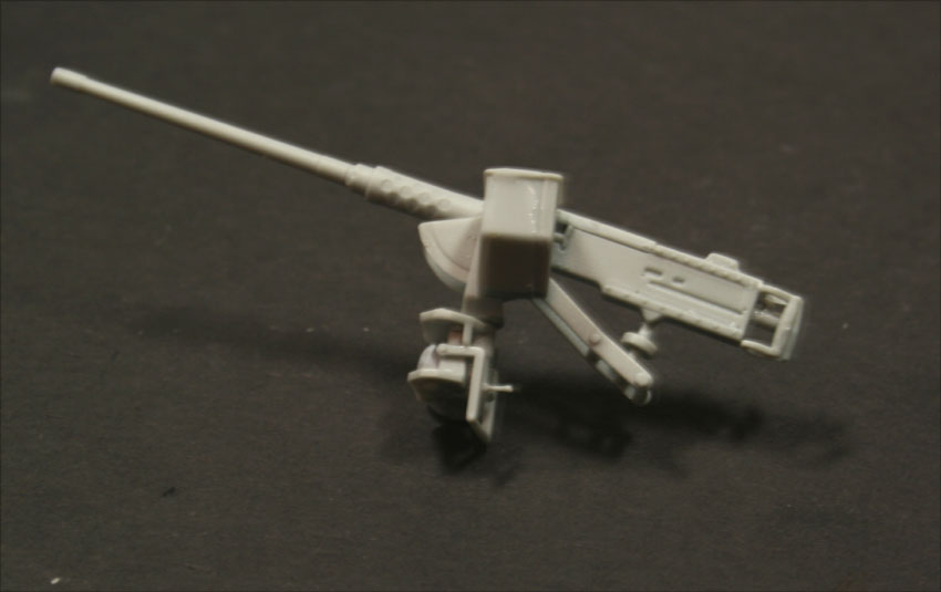
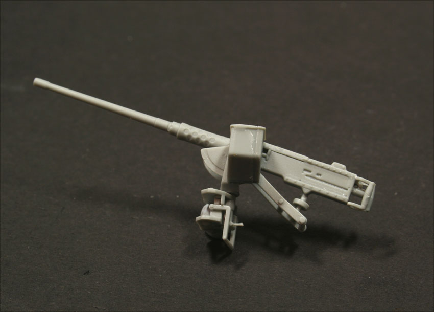
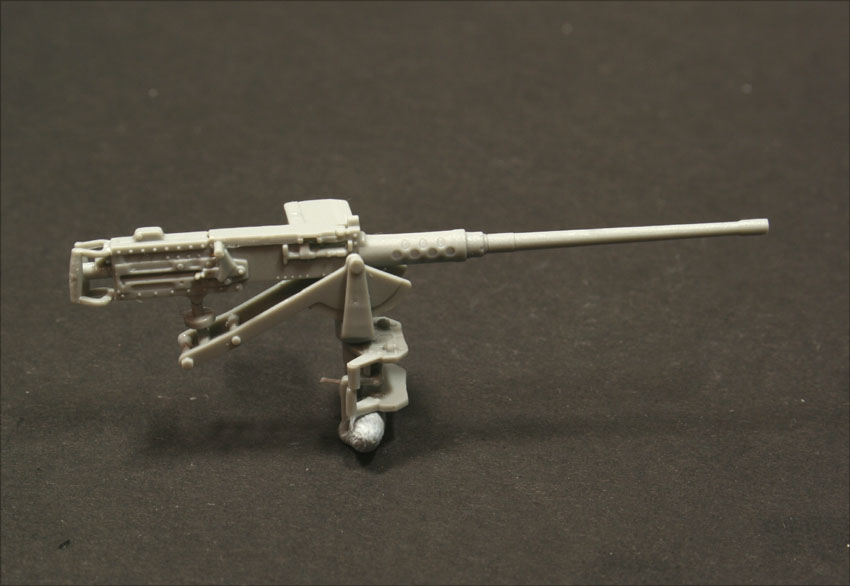
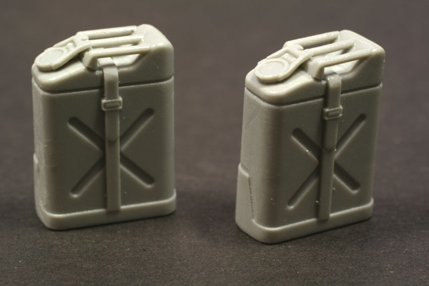
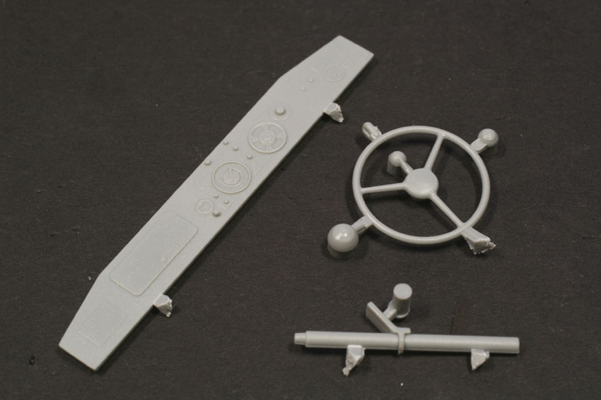
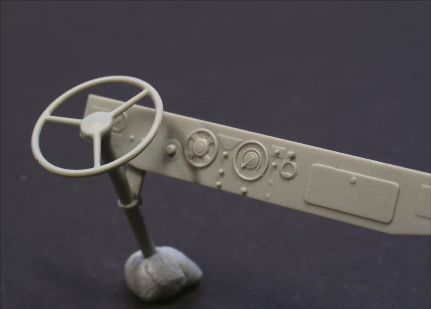
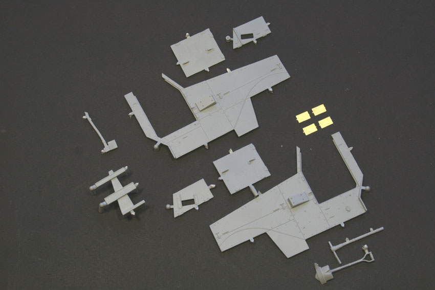
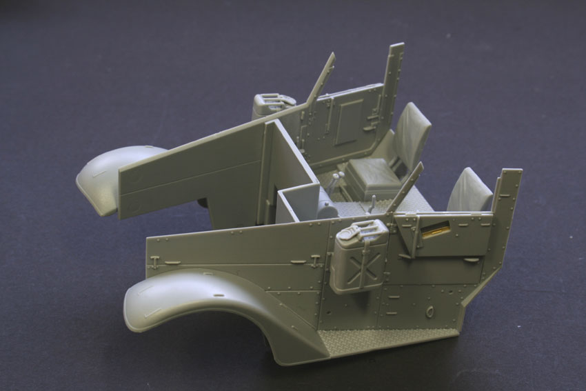
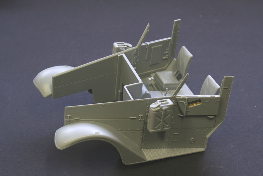
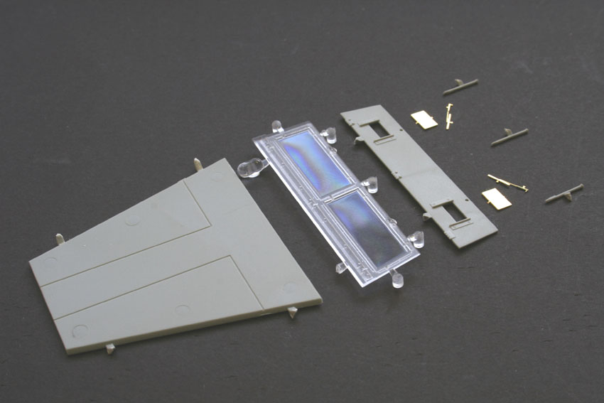
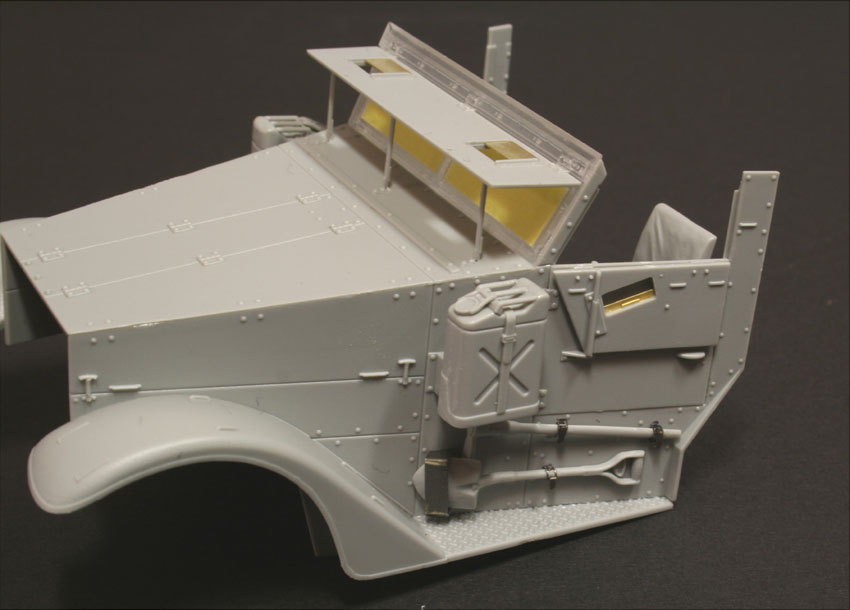
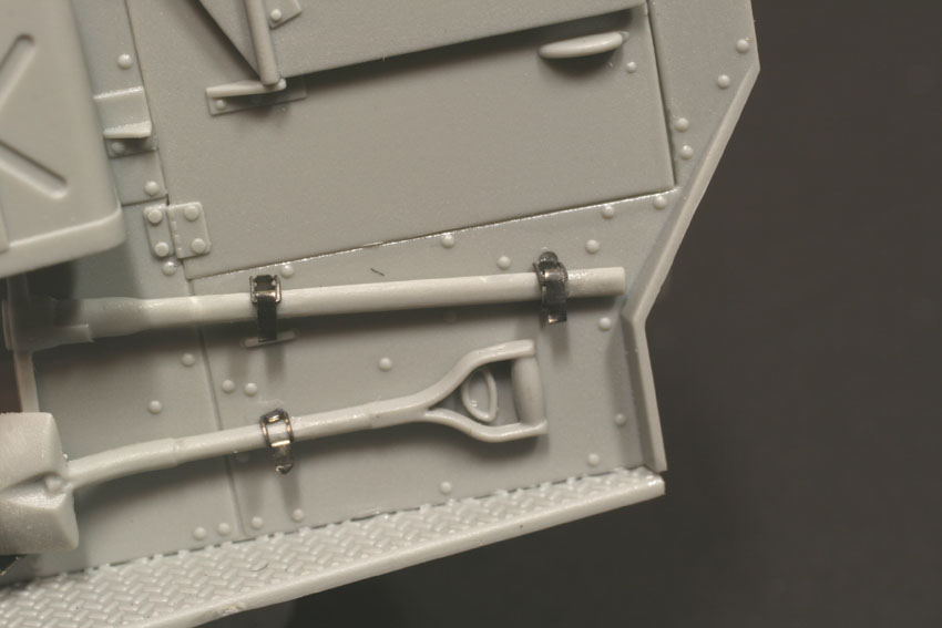
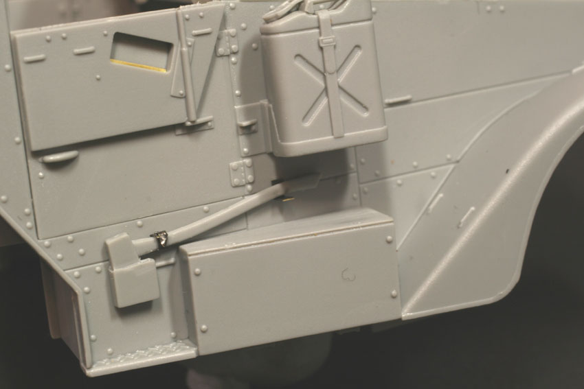
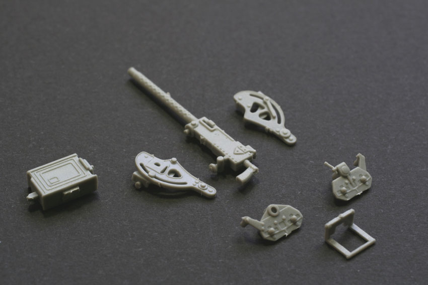
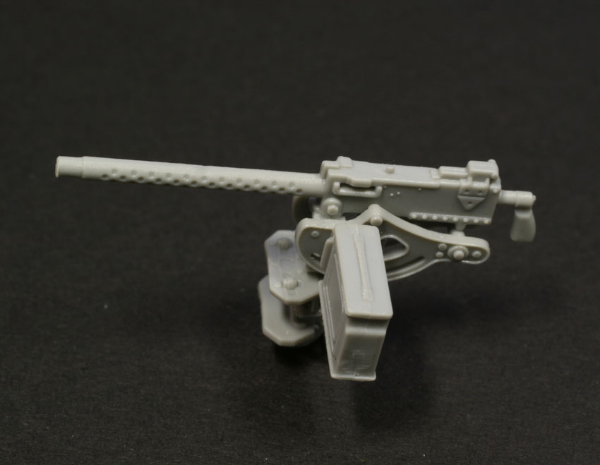
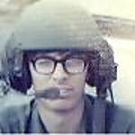
In stage 7 the instructions show the two front wheels being fitted, but I left these off for easier painting. Stage 9 details the beginning of putting all that lovely bodywork together! This begins with the front cab and hood. As mentioned earlier, there are panel lines engraved onto the inside of the hood, so if youve chosen to display the hood open, now is the time to begin work cutting! For the rest of us its simply a matter of building the two-part seats, and cleaning up the gear stick and other levers located in the drivers area. The seats already have a nice texture moulded into them, and the only thing I didnt like about this area was the fact that the foot pedals are moulded into the floor. However, these are easily replaced if you want to with some spare PE or plasticard. When come to fit the toolbox, part B4, onto the right fender, its placement is critical, and theres a small insert to show the exact placement, so line everything up as in the insert and you should be OK! Stage 8 details the assembly of the .50 cal, and its one of the best Dragon has ever moulded. Pre-drilled barrel, multi-part assembly, it looks great! The mount is extremely fiddly to build, but just clips into place on the ring when complete ..just make sure you give it a while to dry and gain some strength! Now we come to another thing I didnt particularly admire about this model, the jerry cans! I just dont think that they can ever look really good when moulded integrally with their holding brackets. I still dont. I realize that a PE bracket might have been impracticable since this kit is supposed to be a Smart Kit, but it should be possible to produce an injected bracket separate from the can itself, and therefore give us the option of making retaining straps that look a little more realistic? Construction continues into stage 10 and mating of the cab sidewalls to the floor. Although I more or less followed the instructions, I diverged a little here to improve the look of the tools on the outside of the cab. They have moulded on straps and look a bit plain. Its a simple improvement to use the ones supplied in the kit without the moulded clamps and use strips of lead foil instead. Remember, unlike the German vehicles of this time, the Allied vehicles such as the M2 used straps, and these are much easier to replicate, with the addition of a few spare PE Eduard buckles I had in my spares box. If you dont have any spare buckles, then fine wire can easily be bent into a rectangular shape and used instead. At this point in the construction we also get to use the PE sliding visors for the vision holes in the cab armour. These are simply super glued in place, and no styrene alternatives are supplied, so again, look after them! At stage 12 we are offered another choice that this time applies to both the M2 and M2A1, whether or not to have the armoured windscreen cover closed or open. I decided open .. it just looks so cool! The windscreen for the M2 is supplied as a transparent moulding, so before I started work on the assembly, I cleaned it up and masked both sides with masking tape. The three small supports for the cover are very fragile. In fact, mine broke during assembly, so were repaired with superglue and then sanded smooth, so take care, and note that if you choose to display it closed, the supports to use are different ones. I suppose there is an argument to be said for leaving the whole cover off until you come to paint, but if youre careful, and have used superglue for its construction, its fairly robust. This stage also instructs us to mate the hood and windscreen with the earlier prepared cab. Its starting to take shape!which version?
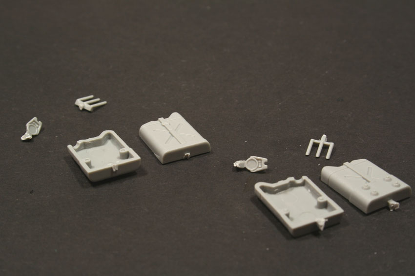
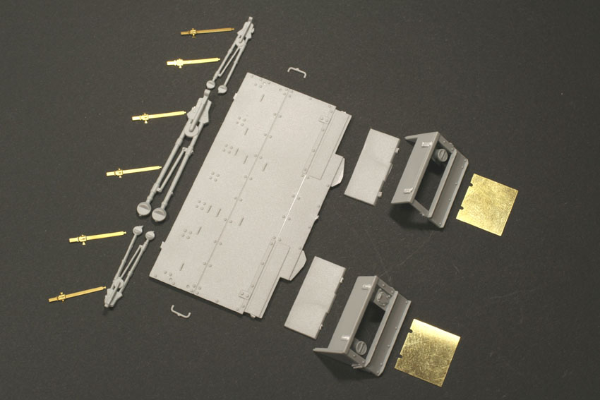
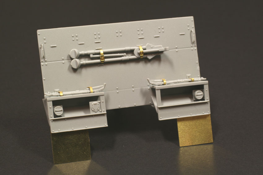
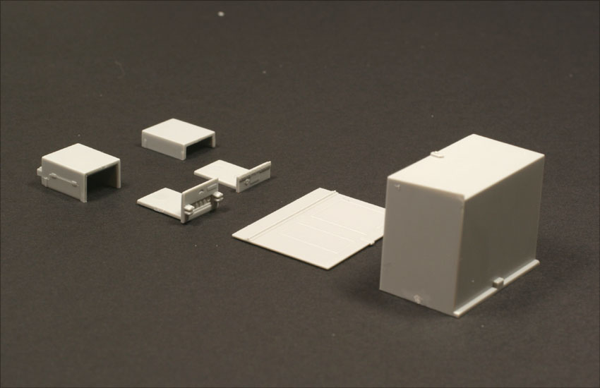
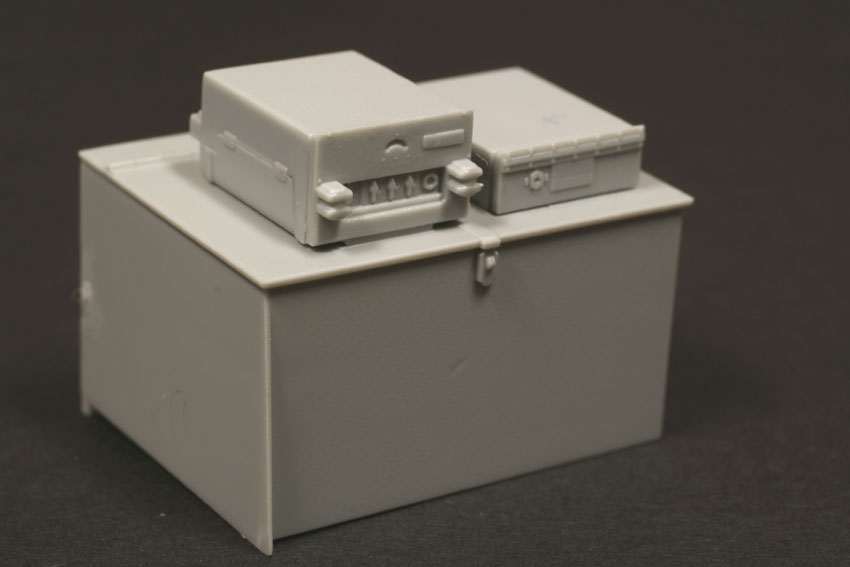
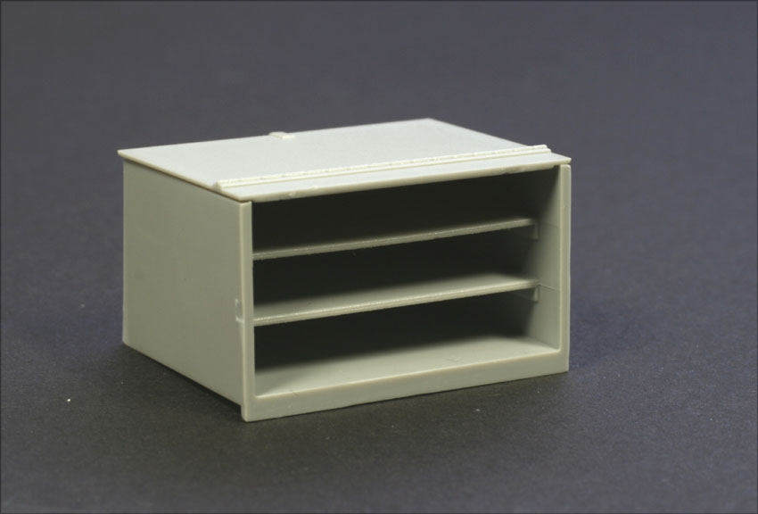
Although I had to make the decision earlier whether to make the M2 or M2A1, its at stage 13 that the instructions themselves actually diverge into 2 streams. As I was making the M2 I just carried onto the next stage, but if I had have been making the M2A1 I would have had to jump a couple of pages to the alternative stage 13. The M2 stage 13 deals with building the rear wall of the vehicle, the only difference between this part (K8) and the rear wall for the M2A1 (K9) being the supports for the skate ring on the inside. Its here were instructed to install the 3 tripod mounts for the .50 Cal and 2 .30 Cals. Interestingly, Dragon actually do provide PE straps for retaining these, I attached these around the mounts first, and then attached them to the wall. Make sure that parts K7 are correctly inserted and that both rear fender supports are dead straight in relation to each other. The two PE rear mudflaps can then be simply super glued to these, and they each have two small slots to make sure theyre straight. Stage 14 is the building of the two large lockers that are placed inside the rear body of the vehicle, along with some radio gear atop one of these. The large locker on the left is supplied with shelves to fit inside it, although no provision is made for having it displayed open, but with a little corrective surgery along its hinge line, it shouldnt be too difficult to do. This stage also shows the construction of one of the two .30 Cals, most people will need two, but the instructions dont mention this. In stage 15, I installed the two plates that form the underneath of the rear body. It is really easy to install these the wrong way around! I know this from experience! If you do, it means that much later in the build, the body will not sit on the chassis properly ..so take care! At this stage you also install the lockers you made in the last stage, and the foot rail around the bottom of the crew compartment.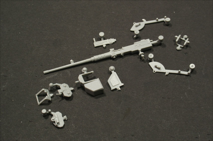
About the Author


Comments

If nothing else, this proves that DML at least listens to the discussions going on via forums around their kits. I take that as a positive indicator of awareness at least and willingness to acknowledge concerns one way or the other.
NOV 13, 2006 - 12:25 AM

And how long will it be until we see a pic posted in the gallery with the little bulge postioned at the top? :-) :-)
NOV 14, 2006 - 02:05 PM

This thread is pedantic to say the least. Who cares if there's a bulge in the tyres? It really is not that important in the greater scheme of things! If you don't like the look of it then don't buy it but stop whinging about it! As an Allied modeller I'm overjoyed that this kit has been released to replace the bog awful Tamiya half track. If that's the only inaccuacy anyone can find on the kit I'd say DML have done a fantastic job..just forgot to inflate the tyres to the correct PSI as you can always do that on a battlefield under fire. Get a grip
NOV 15, 2006 - 05:34 AM

There you are. It's not as if the Dragon tyre has a wrong thread pattern, or the wrong number of wheelnuts, or is the wrong size.... it's only underinflated.
How about using the Tamiya front wheels? They don't bulge...
Henk
NOV 15, 2006 - 08:32 AM

Excellent article, Vinnie! I just got my M2/M2A1 kit last night and am chomping at the bit to get started. This kit looks like one of those rare "box shakers" that require only some glue thrown into the box, which is then shaken and out comes a built model. :-) Seriously though, I could find no reference to "glitches", or problems with this kit, in your article (at least not major problems) and I am looking forward to getting on with this project. Once again, well done. Dave
NOV 18, 2006 - 02:19 AM

Well I just got my halftrack today, and gone through it several times, wiping up the drool as I go, and this is coming from a non-allied builder! :-)
I had a look at the little "issue" people have with a couple of certain parts, they look fine to me. Mine will be goin in a dio anyways, so they propably won't be noticed. But what a kit! and now it's promptly going into one of my boxes, as I'm packing to move!
NOV 18, 2006 - 08:05 AM
For any of you who might be interested, a tweaks list for this fine kit has been posted on ML. My buddy Jay did a lot of detective work and has very comprehensively listed many of the minor adjustments needed to make a great kit even greater. Give it a look! Happy Thanksgiving folks! Dave
NOV 22, 2006 - 06:52 AM

Well, enough of the tires. Vinnie, what you are missing is the cover for the gaping hole in the crew compartment. A lot of people are missing this, it is in the directions but it's very hard to miss. Even the one in AFV Modeler is missing it, I almost did too, had to add it after the model was built.
Jim
DEC 13, 2007 - 04:20 PM

James, there's little point in posting as a response to this feature. The author of the article is no longer a member of this site..
DEC 13, 2007 - 08:51 PM
Copyright ©2021 by Vinnie Branigan. Images and/or videos also by copyright holder unless otherwise noted. The views and opinions expressed herein are solely the views and opinions of the authors and/or contributors to this Web site and do not necessarily represent the views and/or opinions of Armorama, KitMaker Network, or Silver Star Enterrpises. All rights reserved. Originally published on: 2006-11-07 00:00:00. Unique Reads: 48591

WEB HOSTING BY


Copyright ©2021 Armorama and Kitmaker Network, a subsidiary of Silver Star Enterprises
All Rights Reserved. Please read our Conditions of Use and Privacy Policy.
All Rights Reserved. Please read our Conditions of Use and Privacy Policy.