

1⁄35French Heavyweight Char B1 bis
21
Comments
Construction Cont'd
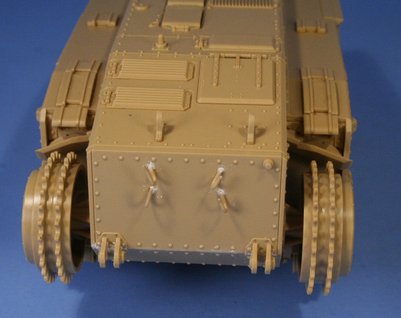
Step 11 is where I encountered the only real need for any kind of putty and sanding work. The installation of the glacis plate and construction of the armored drivers hood require that some of the inevitable seams that result be filled in and sanded down to achieve an accurate look. The drivers hood was a single cast piece and the Tamiya assembly steps result in an L-shaped seam along the side and where it joins the glacis that needs to be filled. The mantlet for the 75mm howitzer also requires some putty work as it should be a single piece with the bolted frame around it but the installation over the gun housing produces a seam that shouldnt be present. In addition, the bolt holes for the foul weather cover are missing, so I drilled out 6 holes around the face of the mantlet to replicate this. I also used this opportunity to install the missing two mud scrapers that are on the side of each mud chute by converting some scrap PE parts with a side cutter to the necessary shape and glued in place with CA gel.Step 12 installs the side boarding hatch for the crew and has some nice detail on the interior face but I elected to install this in the closed position as the interior is truly cavernous and quite empty without any trace of an interior.
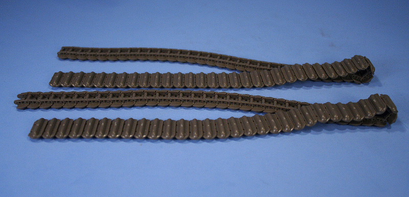
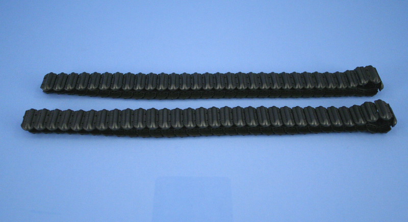
Step 13 involves one of the truly magical parts of the build, the tracks. The Chars unique track system is done a real service by Tamiyas choice to provide them as individual clickable links that literally assemble in minutes. The only cleanup is a slight bump on each track face that is easily taken care of. The instructions recommend 61 links per side, which works out perfectly, although 8 extras are provided if needed.
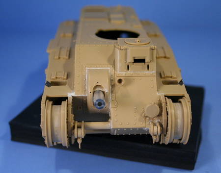
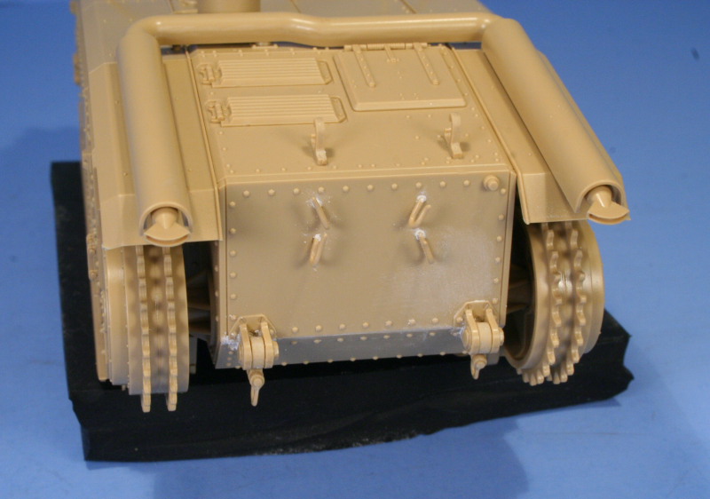
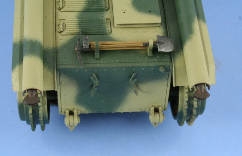
Step 14 required some slight putty work to fill in the holes for the rear chain mounts as well as the rear tow pintles. Since the rear hooks will take the tow chains, these were cut with a #11 blade to allow for their fitting later on.
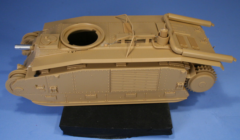
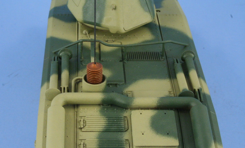
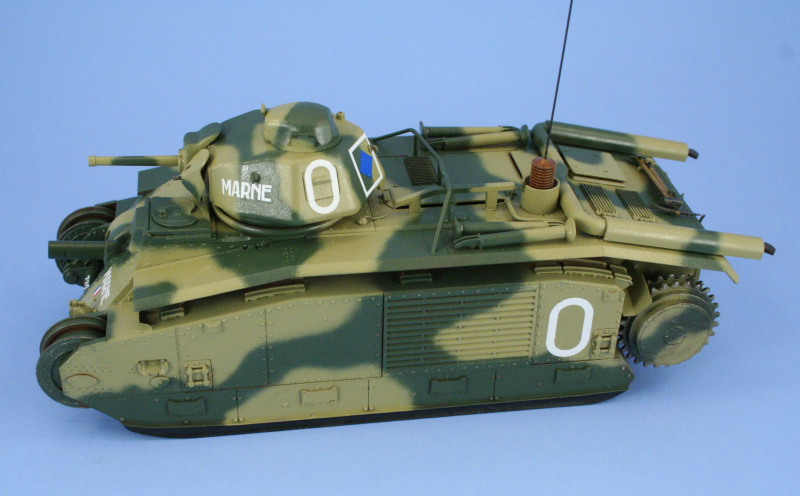
Step 15 provides a choice of either spaced or flush fenders and the flush were installed for Marne. It was also necessary to modify part B21 from its solid molded form to a hollowed out square at both ends and some small gauge wire used to simulate the antenna radio cable connecting the antenna to the radio in the hull. The large square bolted plate just behind the turret ring was removed and sanded down and a converted small headlight face from the spares bin converted into an insulated cover with a hole drilled into the top to accept the wire.
Step 16 provides a choice of mufflers and exhaust styles and the straight fishtail type were installed as the correct type for Marne in Step 17. This same step also calls for the installation of the concertina style antenna mount but I left this off to allow for easier detail painting later on. The two-part assembly does create a delicate seam on both sides that needs some careful work to remove, accomplished through the use of liquid glue and a knife point under the magnifier. Step 18 deals with the installation of the chains which I skipped until after painting was completed.
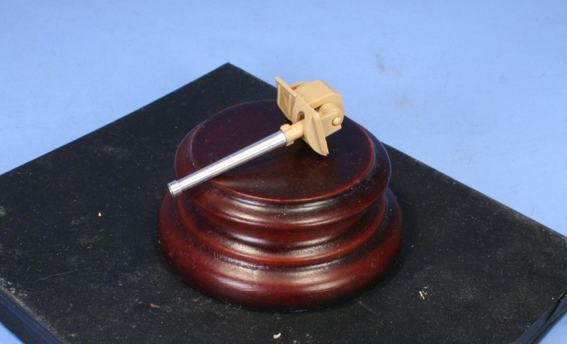
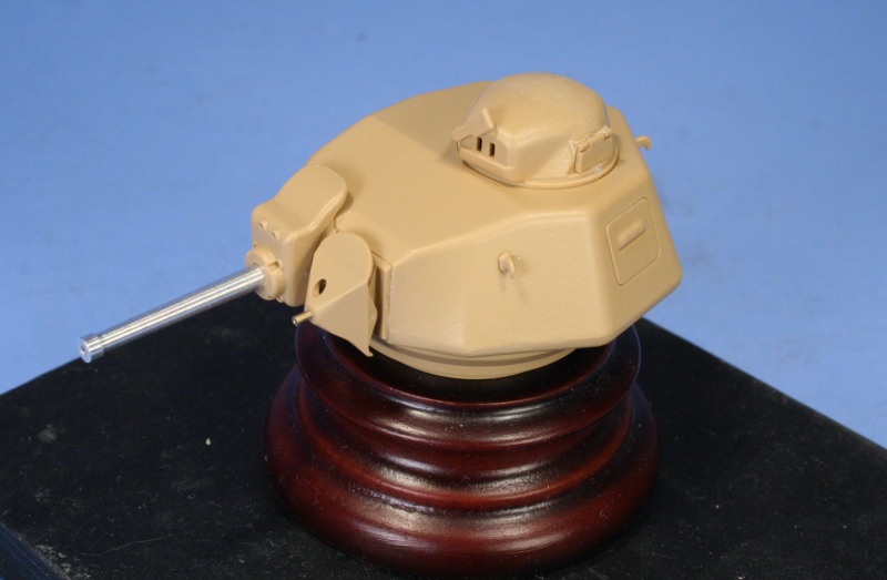
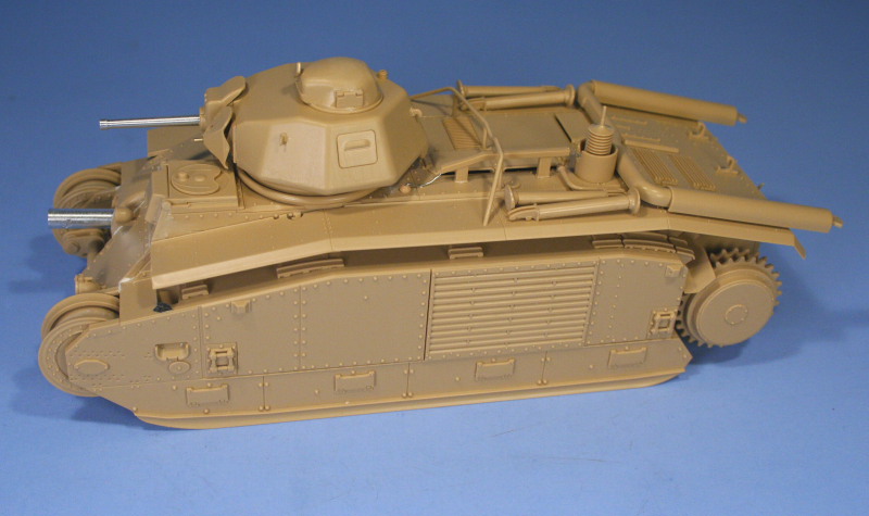
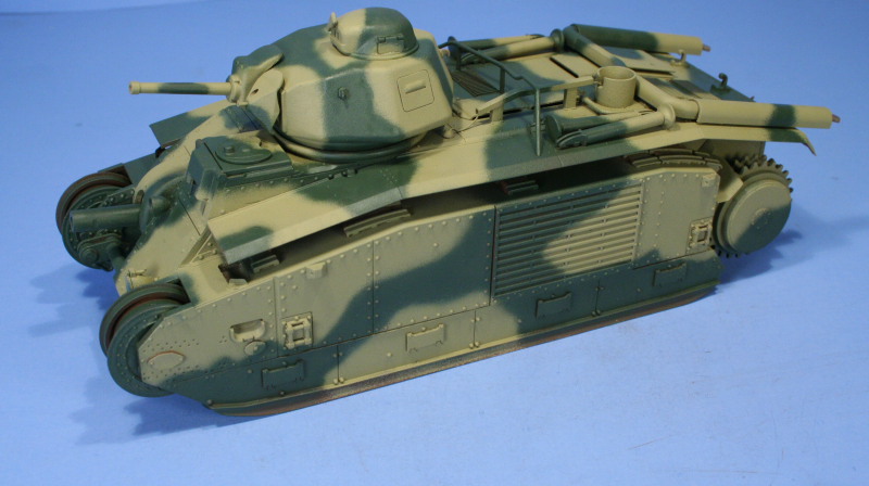
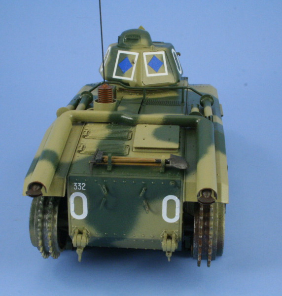
Steps 19 and 20 deal with the turret and here more surgery is required to use the Lionmarc 45mm gun. Only the base of the Tamiya kit part is needed so the barrel was cut off with sprue cutters and the stub sanded down to accept the aluminum barrel. The rest of the assembly went smoothly and the turret was constructed by joining the top and bottom halves together and the slight seam that resulted sanded down after the glue had set up. Finally, the Lionmarc turned brass coaxial MG muzzle was installed in place of the Tamiya kit part and major construction was complete.
About the Author


FROM: TEXAS, UNITED STATES
Like many, I started out in the hobby as a kid building airplanes to hang from my bedroom cieling. I took a long break from the hobby, returning in 2001 with an interest in armor inspired mostly by online gaming. WW2 armor, 1/35 scale, is my preferred genre with a special taste for the stranger vehi...
Comments


After reading (and enjoying greatly) your build article, my only regret is that I have already built mine...although it was a very quick and fun build, I'm sure it would have been much better had I been able to read your article first.
MAR 12, 2007 - 07:48 PM

Bill VERY nice build! You did this baby justice!
One question, I'm interested in how you made your rusty track wash? What did you use and what was the ratio? I reallyn like the way it came out.
Thanks
Jim
MAR 12, 2007 - 09:53 PM

Ron, Gary, Jim, thanks for the comments!
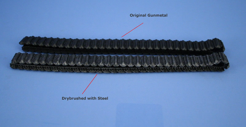
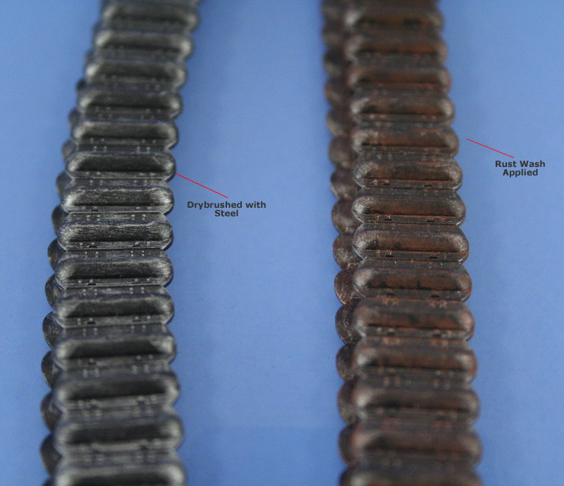
My rusty wash is simple, 90% thinner, 10% paint more or less. Here's what it looks like when it's "settled" to give you an idea of the ratio. The thinner is cloudy because it picks up some of the Metalizer over time and that just adds a bit of "character" to it I guess. :-)

MAR 13, 2007 - 07:58 AM

Nice Bill...very nice - article and build...
Let me know what you think about mine!
MAR 14, 2007 - 04:04 AM
Outstanding article and beautiful paint job! One comment if I may... The jacks on the fenders should be secured with some type of retaining tie downs. They wouldn't just sit on the fenders. Also, I have never seen 4 of them mounted on one tank. The kit came with 4 simply because Tamiya included two identical sprues in the kit. More than 2 is redundant. They were used to jack up one side of the tank at a time. Don't know of any way they could raise the whole tank off the ground without a crane. My jack comments aside, best build article I've seen in a long time. I enjoyed it.
MAR 16, 2007 - 04:50 PM
Bob,
Thanks for the comments, what you are saying makes sense in regards to the jack stands. The Tamiya instructions direct for all 4 to be installed and not knowing any better at the time, I followed along and installed them. In checking various reference photos since building this one, it's difficult to determine if there was in fact any sort of standard placement for them in relation to the fenders or the rear deck...or if they were installed externally at all depending on the different vehicles and the available reference photos.
MAR 16, 2007 - 10:04 PM

Bill,
Awsome SBS Sir....already book marked for my Char. I too have the LM set of barrels on the way. I'm either going to do a similar paint scheme, or once I get the hang of my DA airbrush, may do one of the "tree" patterns...not sure yet. Regardless, your article is killer and will be of great assistance.
Many thanks (and congrats on your new [heheheh] position!!).
Mike
MAR 16, 2007 - 10:49 PM
Thanks Mike! The different units and timeframes offer up a wide range of possibilities when it comes to the Char paint schemes. The tree patterns being one of the more intriguing to be sure! Look forward to seeing what you do with yours.
MAR 17, 2007 - 05:42 AM
Hi Bill,
I've seen photos with the jacks stowed on either the right or left fender so I don't think anybody could say one side is right and the other wrong. Most of the photos I've seen don't show them at all. I suppose it's possible they were stowed inside the vehicle although I wonder if perhaps because of their size whether many Chars didn't carry them at all and depended upon a support unit to provide the necessary lift when required. After all, how often would a crew in a combat zone be able to take the time to deploy to jacks and tilt the tank to one side? My guess is that maintenance units ultimately did the dirty work once the battle had moved on. Regards and I look forward to further examples of your work. Very well done.
MAR 17, 2007 - 07:19 AM
Copyright ©2021 by Bill Plunk. Images and/or videos also by copyright holder unless otherwise noted. The views and opinions expressed herein are solely the views and opinions of the authors and/or contributors to this Web site and do not necessarily represent the views and/or opinions of Armorama, KitMaker Network, or Silver Star Enterrpises. All rights reserved. Originally published on: 2007-03-10 00:00:00. Unique Reads: 21705

WEB HOSTING BY


Copyright ©2021 Armorama and Kitmaker Network, a subsidiary of Silver Star Enterprises
All Rights Reserved. Please read our Conditions of Use and Privacy Policy.
All Rights Reserved. Please read our Conditions of Use and Privacy Policy.