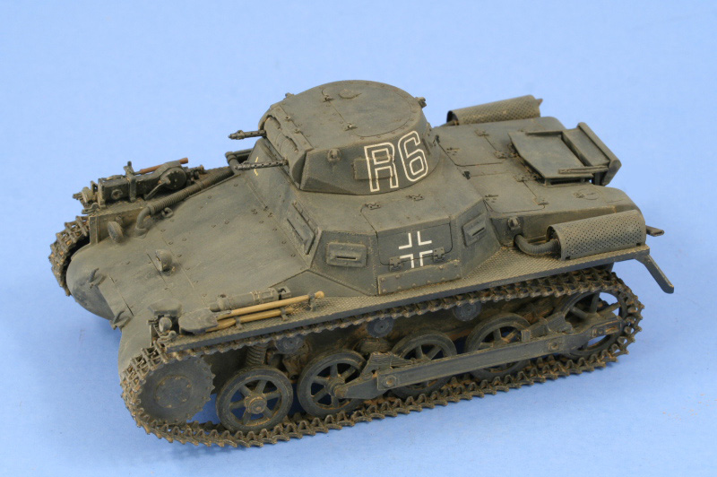
1⁄35Building DML's Pzkpfw I-A Mod Version
...
Post a Comment
Introduction
The PzKpfw I Ausf A is often referred to as a ďtrainingĒ tank however when it was designed in the early 1930s, it was meant to be a combat vehicle from the beginning right down to the specifications on the armor being able to withstand infantry-caliber armor piercing rounds. The first in the series of German Panzer designs, the Ausf A was produced in larger numbers than its better known successor, the Ausf B, and underwent post-factory modifications as well to meet field conditions. The subject of this build, DMLís kit #6356, will be built to represent a Series 3 vehicle with field modifications compatible with a war-time vehicle in service in France in 1940.Suspension and lower hull
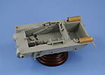
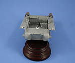
The build begins in the usual place with the road wheels and suspension. The wheels were constructed using PE inserts on both sides to complete the hubs. Each insert was slightly concave and a pair of locking tweezers employed along with liquid glue to get each hub to sit flush on either side, a slow-moving process for all 16 inserts required. Each of the road wheels and return rollers were sanded to remove the slight mold seam present and the suspension elements were cleaned up and set off to the side for detail painting later on. The multi-part idler wheels were also constructed along with the spring arms and coils for the first road wheels. The lower hull construction proceeded with the installation of the front and rear plates helping to stiffen the hull sides and bring them into a square alignment. Two additional plates were installed at the hull front for the front fender sides and these require careful attention to keep them straight due to their narrow contact surfaces.Interior
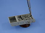
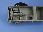
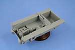
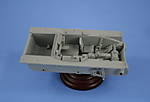
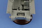
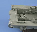
Quite a bit of the kit is devoted to the interior and the first element to be constructed is the 14-part transmission and brake housing. Some of the detail on the brake housing has been simplified somewhat and test-fits are necessary to insure the final drive housings line up properly against the hull sides. The driverís area is a particularly crowded space with a lot of detail packed into it and the placement of the driverís seat needs to be exact relative to the other elements to avoid complications. The absence of locator holes makes this somewhat of a trial-and-error process and I ended up having to shift the seat inward just a bit after test fitting into the hull, but once relocated everything fit beautifully. The interior was installed together and a pair of locking tweezers used on one side at a time with liquid glue to get a solid fit. The rear bulkhead and firewall were also installed along with the crew step that should fit over the starter motor but the motor itself is not included. This, along with the driverís instrument panel and the gas mask canisters above the first aid kit, are some prominent items missing from the kit supplied interior and are strange omissions given the attention to detail on the other elements. For the rest of the interior details, the fenders need to be fitted first since the superstructure overhangs them. The holes were drilled out using a pin vise according to the instruction diagrams and I discovered later that I had missed a couple in the process but that didnít really cause a problem in the end. The fenders, due to small contact surfaces, have a tendency to want to droop so each fender was installed separately and kept square until the glue had set to avoid that. Once in place, the rear upper hull plate was installed along with the ammunition racks along the right side. The left side received its large storage box and armored glass block holder, both of which do not have locator holes provided. Due to this, itís necessary to test fit with the hull superstructure to determine their exact placement as thereís zero tolerance in this space for error. The lower interior on the right side also received the spare MG13 barrel case and signal flag tubes. These parts do not have any sort of locator marks or guides provided, so careful placement for both to avoid interference with the rest of the interior was necessary.Exterior and Superstructure
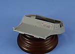
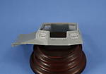
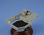
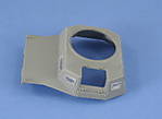
With the interior completed, the exterior got its turn beginning with the glacis plate and brake access hatch. The join with the hull received some light sanding to smooth it out and the tow points were installed along with the access hatch to close up the area. The mufflers and exhaust hoses were also installed along with their heat shield screens. The kit provided PE screens were annealed over a gas flame and then bent to shape with the handle of a large paint-brush and glued into place, a tricky maneuver since they sit on the raised tread-plate of the fenders. The headlights were also installed on the hull front and fenders. The smaller lights are molded solid vs. the large light molded open with a clear lens provided. Since combat photos show these commonly covered with cloth black-out covers, I scratched some round covers with slits out of sheet styrene and used them instead. The rear mud-flaps were installed along with the Notek convoy light and jack block holder although the jack block itself was left off until later. The superstructure assembly came next and involved a mix of interior and exterior detail steps. The superstructure exterior consists of a frame and a series of plates that are attached to the outside and join together at the weld seams to form the exterior surfaces. Each plate joined smoothly to its neighbor, requiring only small amounts of liquid glue and pressure to assemble all around. The interior, since itís borrowed from the Early Pzkpfw I A kit, has an extra vision port on the rear right side that has to be blanked off on the inside. I did this with some thin sheet styrene glued in place and then sanded down smooth to the hull sides. Each of the vision ports were constructed and installed in the closed position, taking care to keep their interior frames flush with the superstructure on both the inner and outer surfaces. The superstructure interior details include the driverís radio, antenna raise/lower handle, and a small stowage box but again no instrument panel. While the kit includes a nice PE frame for the radio, its etched double-thickness in places made it extremely difficult to bend and I ended up not using it as a result. The upper roof plate rounded out the installation, matching up near-perfect with the side plates, with just a bit of sanding required on the front edge. The turret ring is designed as a friction fit for the turret proper and as such doesnít have the old-fashioned ďear-slotĒ arrangement, preserving the whole detail on the ring in the process. As a final step for the exterior, the engine deck was constructed including the field-modifications for the intake screens and installed. I discovered at this point that Iíd made a slight error in the installation earlier on with the top rear bulkhead. Itís out of position by about 0.5mm and produces a slight offset between the engine deck and the superstructure as a result. This was partly corrected with some careful putty application and is my error and not the kitís.Copyright ©2021 by Bill Plunk. Images and/or videos also by copyright holder unless otherwise noted. The views and opinions expressed herein are solely the views and opinions of the authors and/or contributors to this Web site and do not necessarily represent the views and/or opinions of Armorama, KitMaker Network, or Silver Star Enterrpises. All rights reserved. Originally published on: 2007-10-16 00:00:00. Unique Reads: 21152


