

1⁄35Bronco's Marder
10
Comments
Introduction
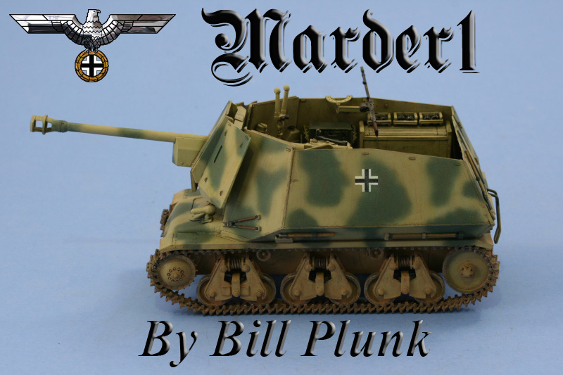
When the Germans first occupied France in 1940 after the capitulation, they captured large stocks of French armored vehicles and other gear. Among the captured vehicles were a large quantity of Hotchkiss H39 tanks and, while not of much use as a gun tank, they were available as self-propelled chassis for heavier guns. 24 were converted to carry the 7.5cm Pak 40 anti-tank gun and were assigned to the 155 Panzer Artillerie Regiment attached to the 21st Panzer Division where they saw combat service immediately after the Normandy invasion. Bronco has released a 1/35 kit, # 35004 in their catalogue, and is the kit used in this particular out-of-the-box project.Lower Hull, Interior, and Suspension
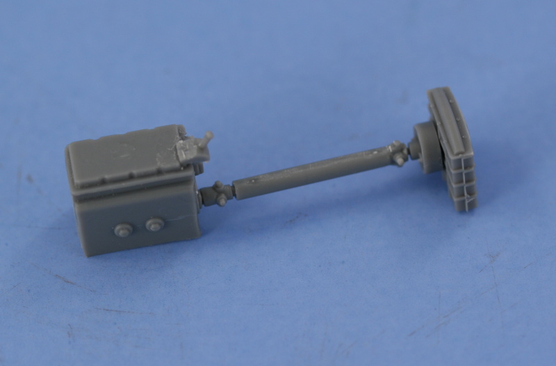
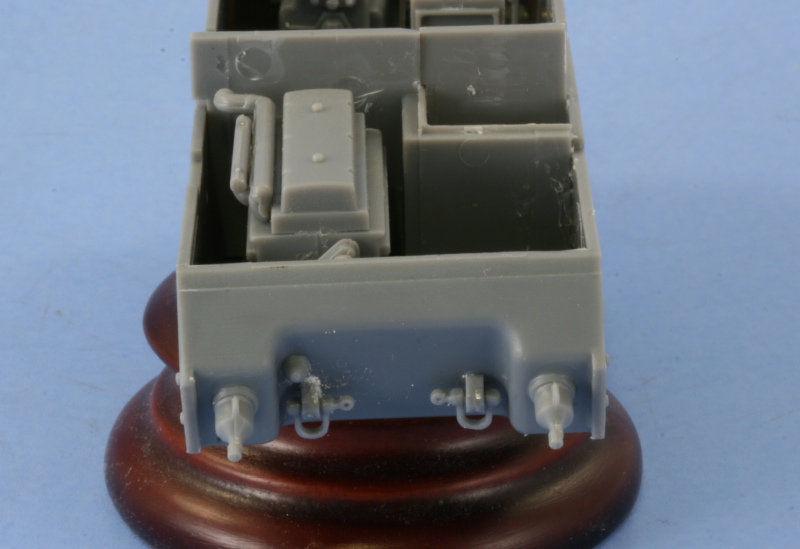
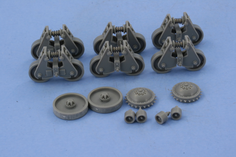
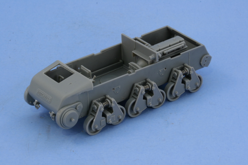
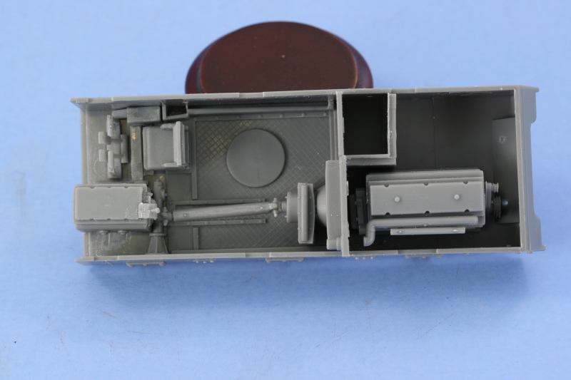
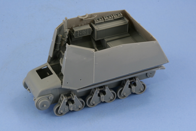
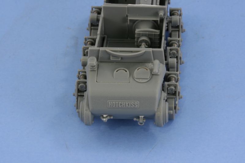
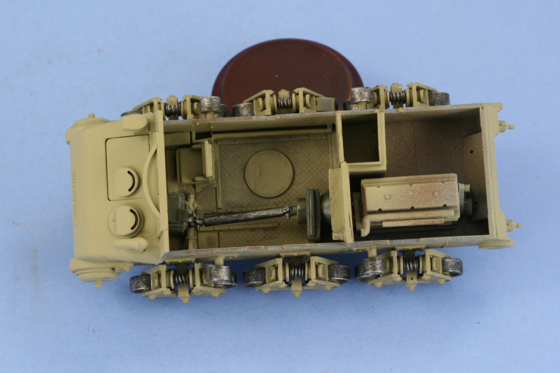
Construction begins with the lower hull and interior. The first items for installation include the internal final drive and transmission elements as well as the radiator and drive-shaft. I left the radiator dry-fit to the drive shaft initially until it was ready to install against the rear fire wall as the fit has to be just right for everything to install properly. Some large raised ejector marks on the floor in the drivers area were carefully removed and sanded down and the drivers controls and seat where installed into position. I then installed the engine fire wall along with the radiator/drive-shaft. I encountered a small issue with the door for the small compartment being slightly too-large in order to fit properly, so it was necessary to sand it down and check the fit multiple times until it would sit properly without bowing out the hull side. The hull exterior also received some attention with the installation of the hull nose, which attached directly to the lower hull. The towing eyes were added to both the front and rear along with the rear idler tensioning covers. The bases for the towing eyes didnt fit the molded slots in the hull, so they were trimmed off and the parts glued directly to the hull with the small remaining gaps filled with putty and sanded down. Next up was the suspension and this was an intricate affair due to the design of the H39 bogies. The kit has these assemble via a series of multiple sub-assemblies beginning with the construction of the spring tubes. I added the metal springs without glue, allowing the tube ends to trap them in place, and then installed them into the tops of the bogie halves. The two halves trap two road wheels per bogie and then the hull attachment portion is added to the center. Once assembled, I set these off to the side to set up, working on the sprockets, idlers, and return rollers in the meantime. The idlers had a prominent seam that needed to be sanded smooth and the sprockets had sprue attachment points between some of the teeth, so careful work with a #11 blade and a needle file were called for. The return rollers were also cleaned up and set off to the side for now. Installation of the suspension bogies proved to be a delicate and tedious affair due to the very limited contact surface between the hull mount points and the bogies themselves. Until the glue sets, the tendency is for the bogies to want to toe-out, so I elevated the hull for 1 hour to allow the glue to set up enough that it could take the weight of the vehicle and then adjusted the individual bogies until I had a level set to both sides. The vehicle was then elevated again and allowed to dry overnight to insure everything was solid before moving on.Fighting Compartment
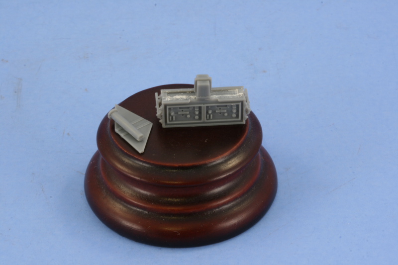
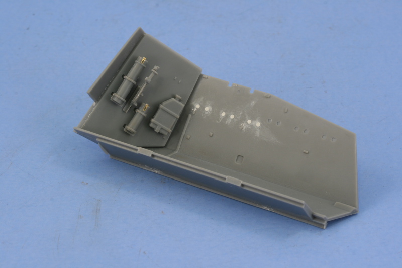
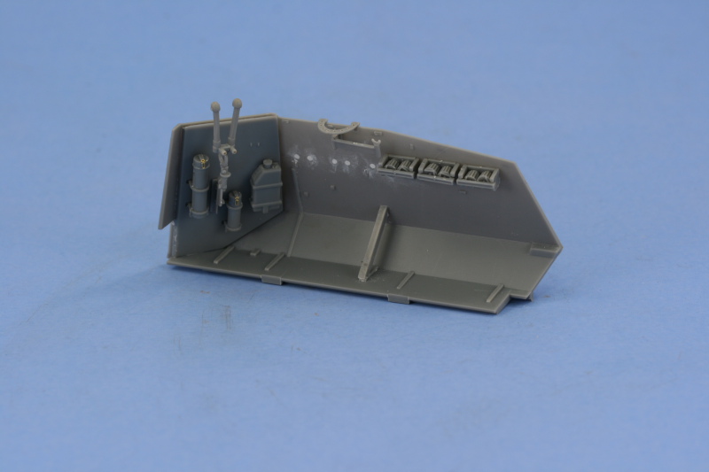
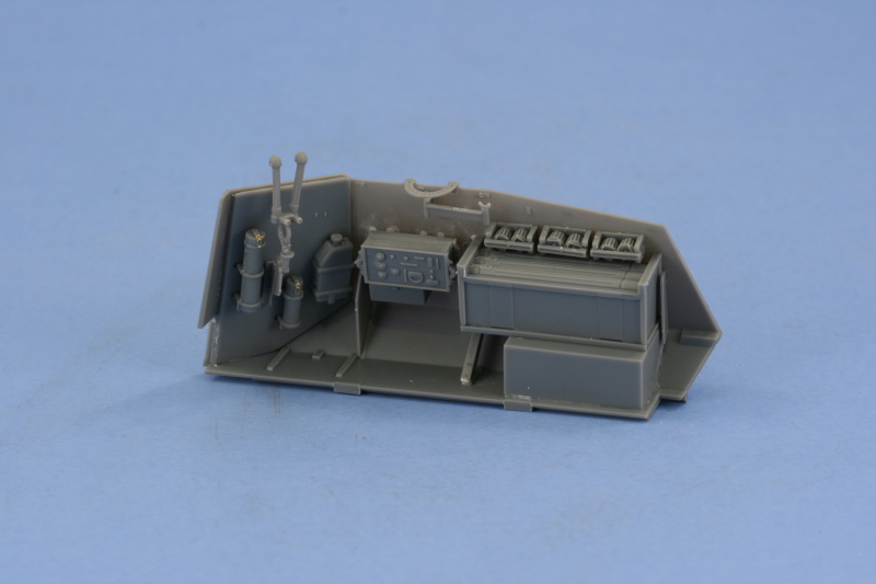
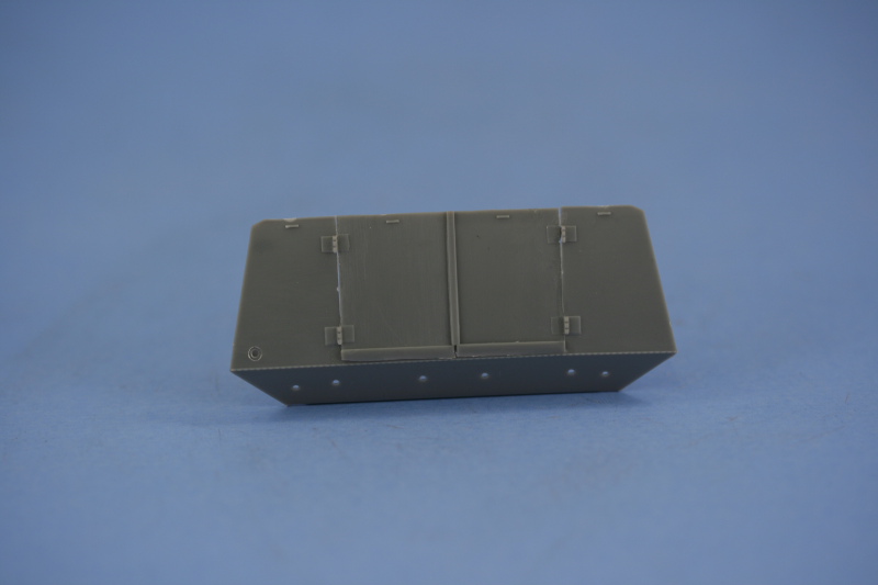
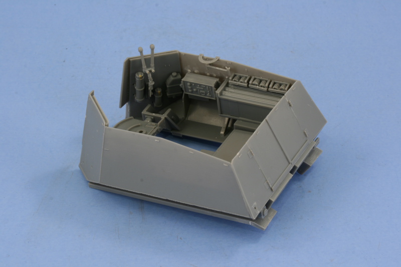
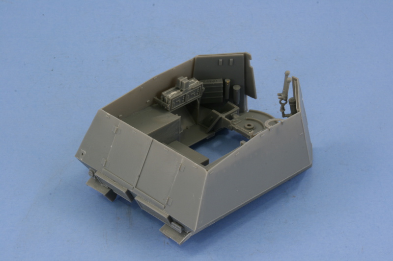
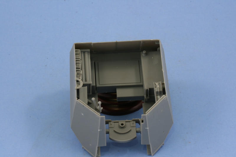
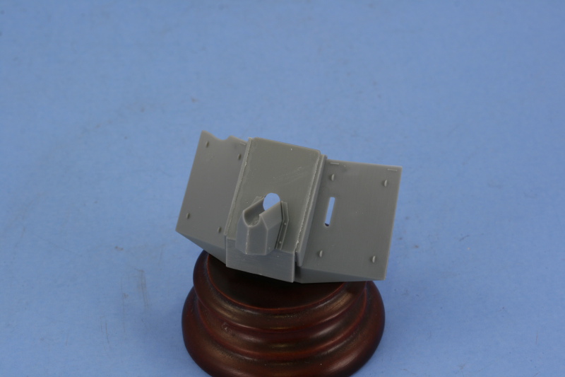
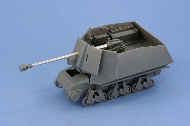
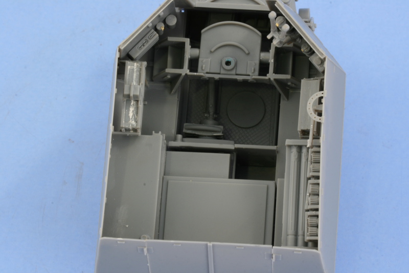
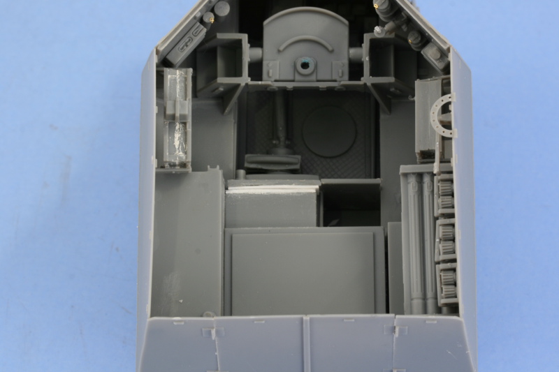
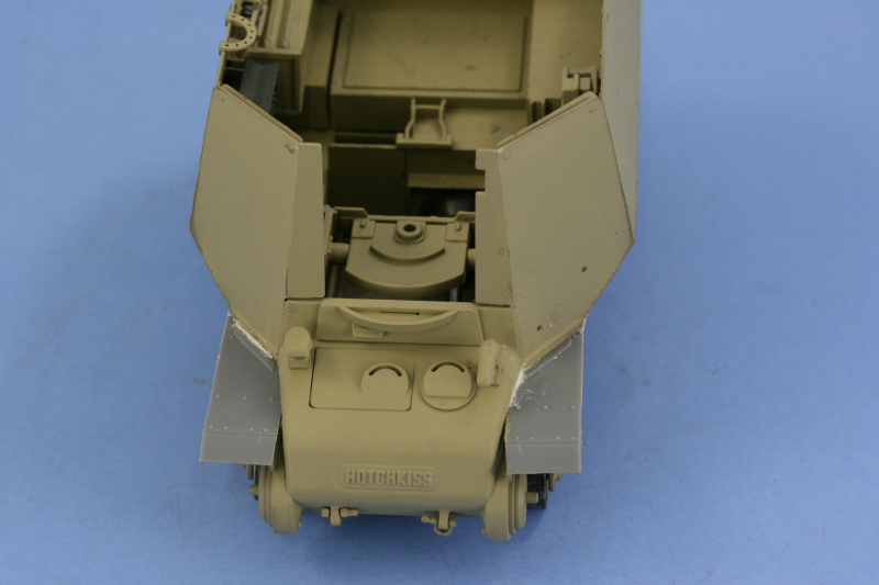
The kit has the fighting compartment separated into two panels for the sides and front extensions plus a separate panel for the rear. Since the modification of the original H39 involved essentially just shaving off the entire upper surface of the vehicle and replacing it with a welded superstructure and gun mount, the vehicle is open-topped in every sense of the word. Fortunately, the kit engineers the superstructure to be totally modular and separate from the lower hull which makes it easy for painting and detailing. I assembled the left side first, installing the front space panel with its various gear along with the vehicles fuel tank and the main radio transmitter/receiver unit. The fuel tank had a large seam that needed to be trimmed and sanded down and the radio assembled from two halves, producing a seam that also needed careful putty and sanding attention to correct. The right side of the compartment received its share of attention as well, with the installation of its spacer panel and gear which included the base of the scissors periscope mount but not the periscope itself just yet. Since this kit is also largely used for another Bronco kit, #35005, that mounts a leFH 18 10.5cm howitzer, there are six mount points on the right side that arent used so these were filled in with putty and sanded down. I also added some detail by drilling out the holes in the semi-circular guard for the crew-defense MG34 using a pin vise and then installed it along with the swing arm mount. The three cases of drum magazines for the MG34 were assembled and installed, using the molded-in mount points as a guide for their placement. The Pak 40 ammunition bin was added along with the secondary radio to round out this sides details. I also installed the missing scissors periscope after drilling out the eye pieces with a micro-drill bit. The rear hull panel was assembled with the access doors in the closed position and then the various pieces of the superstructure brought together into one modular unit. To achieve this, the gun mount is added to the front along with its braces and then the engine compartment cover added to the rear, joining up the side panels in the process with the rear panel. The exterior joins required some light sanding to smooth out their edges. The rear fender portions were added along with the brake light and rear Notek light and everything test fit with the lower hull to insure there werent any issues with alignment.Main Gun
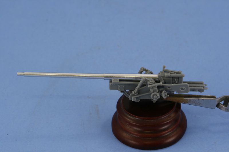
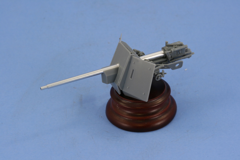
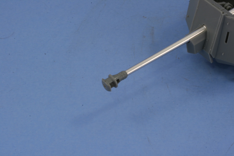
The last remaining piece before painting was the Pak 40 itself. The first step was to assemble the multi-part breech and join it with the turned-aluminum barrel. This step in the instructions involves no less than 12 parts all together in a single diagram, so careful study was needed before committing to glue. It was at this point that I discovered the kit-supplied barrel had an error in that it was 5mm too long, unfortunately its not something that can be corrected short of replacing it altogether and this would cause another issue shortly. The barrel was attached to the breech and recoil sled with CA gel and the rest of the gun constructed including the recoil cradle, elevation and traverse wheels, and the recoil guard. The gun shield and armored recoil housing were assembled next with the two-part recoil housing requiring some light sanding to eliminate its seam at the front. Prior to fitting the muzzle brake, the gun and mount need to be mated up with the gun shield. Due to the added 5mm of length in the aluminum barrel, the gun is forced to sit too far back on the recoil tray and theres no way to correct this since the square front of the tray installs directly into the armored cover on the front and the diameter of the opening in the gun shield blocks the gun moving any further forward, so I had no choice but to leave it as is. The small seam that remained on the breech block itself was carefully trimmed and sanded in order to replicate the correct seamless appearance of the block and I also added the two-piece muzzle brake to the front of the barrel. The brake assembled cleanly and was attached with a small amount of CA gel, taking care to align it properly in relation to the barrel and a test fit into the interior mount showed that everything was sill lining up properly in relation to the hull.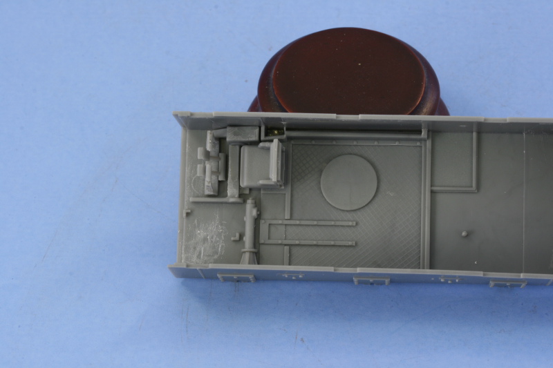


About the Author


FROM: TEXAS, UNITED STATES
Like many, I started out in the hobby as a kid building airplanes to hang from my bedroom cieling. I took a long break from the hobby, returning in 2001 with an interest in armor inspired mostly by online gaming. WW2 armor, 1/35 scale, is my preferred genre with a special taste for the stranger vehi...
Comments


Another great build Bill, thanks for putting this together. Thanks Henk for loading it up! Nice to see unique items.
Cheers -
Tim
MAR 08, 2009 - 04:25 PM


Lyndon, Tim, James, appreciate the comments. My thanks to Henk as well for pulling this one together and publishing it.
MAR 09, 2009 - 02:28 AM

Hi Bill,
Excellent article and a great build on a not often seen kit.
Nice one.
Al
MAR 11, 2009 - 06:01 PM


Great build and article Bill. I hope to build this some day ... God only knows when ... but the big fighting area on the small chasis looks so cool.
MAR 27, 2009 - 10:17 PM
Bobby,
The full build took about 4 weeks to complete from start to finish. Thanks for your comments!
Frank,
Thanks, it's one I could definitely see you tackling. Since you've already done one of the H39s, you already know much of the pitfalls. It's definitely got an oddball look to it...reminds me of a heavily armed clown car.
MAR 28, 2009 - 06:30 AM
Copyright ©2021 by Bill Plunk. Images and/or videos also by copyright holder unless otherwise noted. The views and opinions expressed herein are solely the views and opinions of the authors and/or contributors to this Web site and do not necessarily represent the views and/or opinions of Armorama, KitMaker Network, or Silver Star Enterrpises. All rights reserved. Originally published on: 2009-03-08 00:00:00. Unique Reads: 23953

WEB HOSTING BY


Copyright ©2021 Armorama and Kitmaker Network, a subsidiary of Silver Star Enterprises
All Rights Reserved. Please read our Conditions of Use and Privacy Policy.
All Rights Reserved. Please read our Conditions of Use and Privacy Policy.