

1⁄35D9R Armored Bulldozer
17
Comments
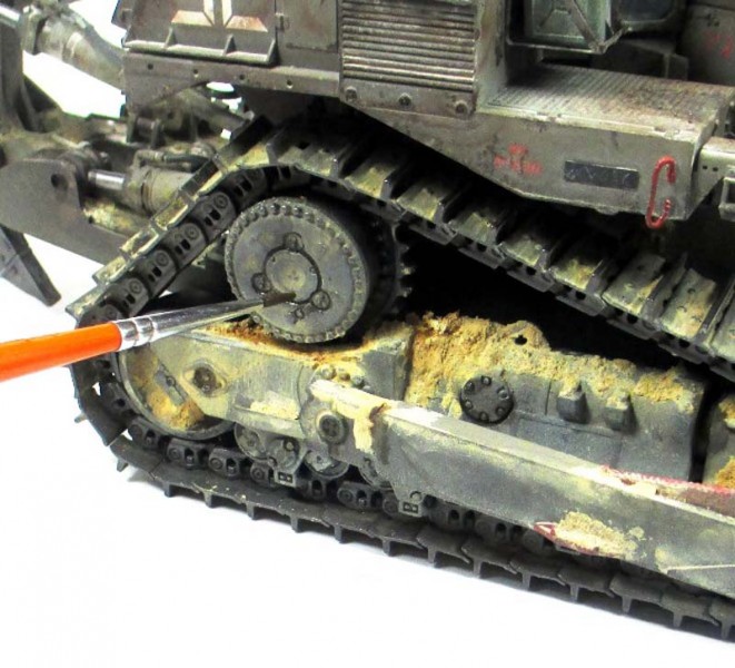
Weathering
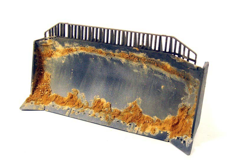
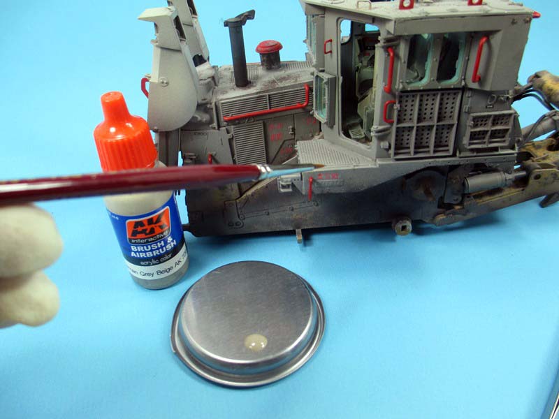
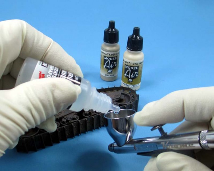
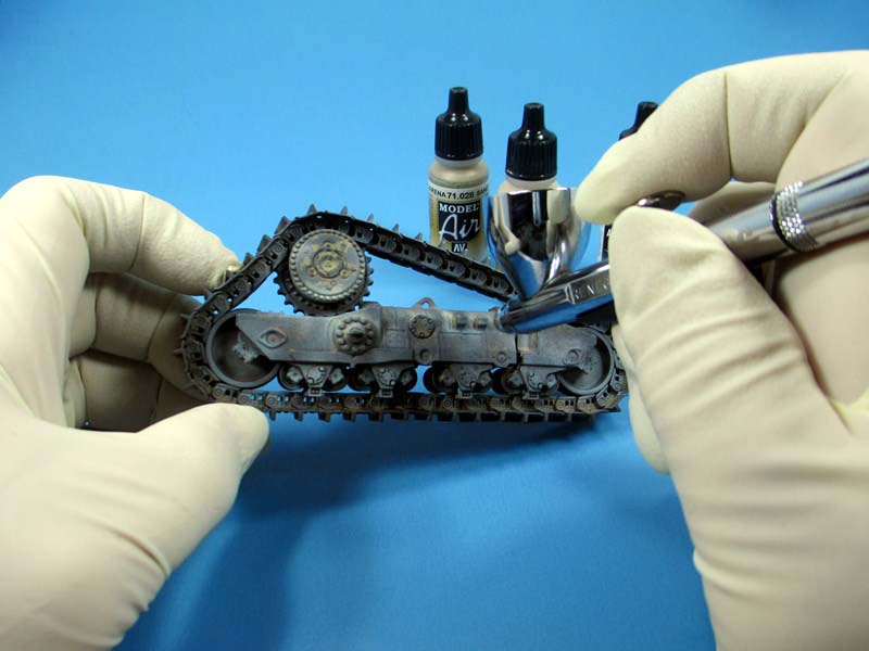
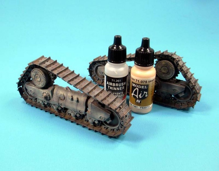
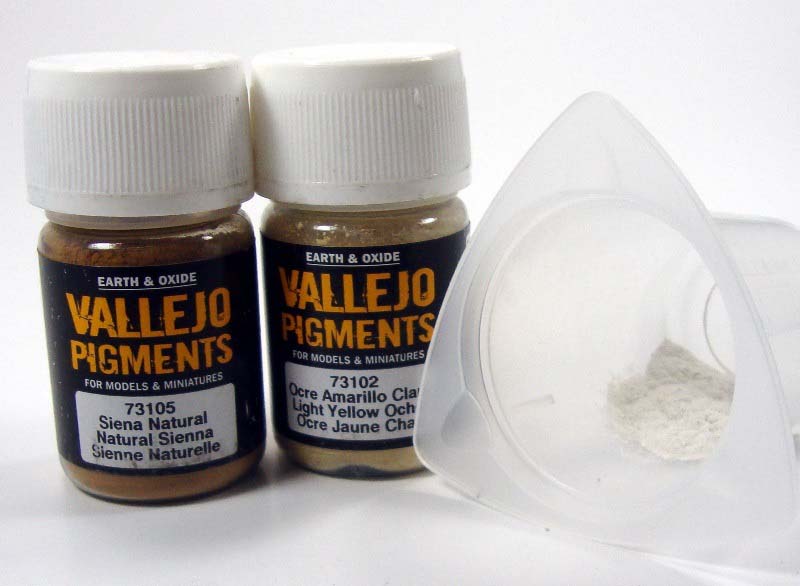
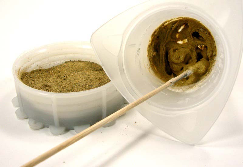
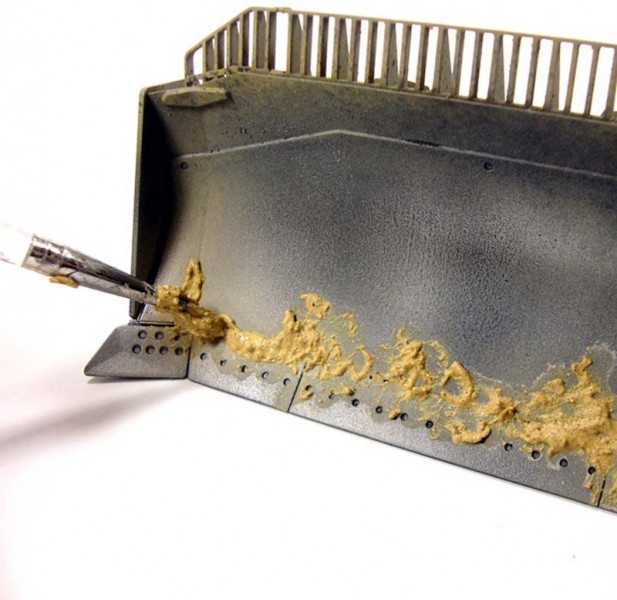
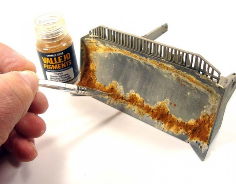
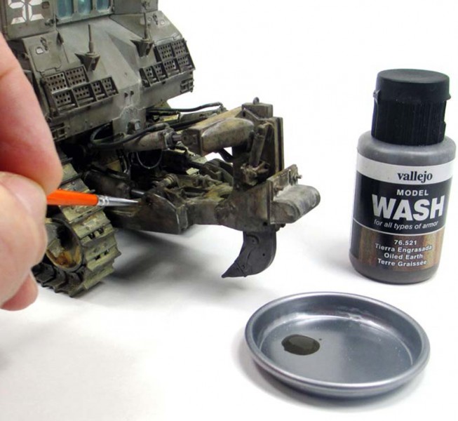
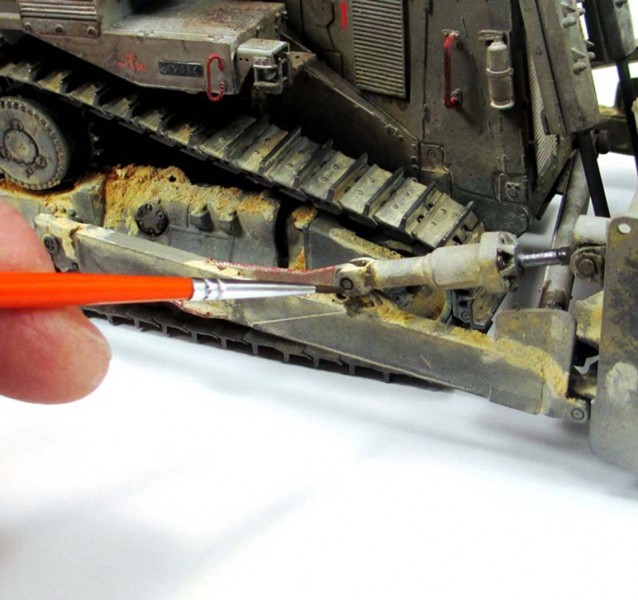
With all the colors in place it was time to start bringing some of the components all together. This is where this begins to look like something. There is some chipping that will be needed on the upper level next. Using a combination of the base color I used for the IDF grey, yellow and various chipping colors to apply chipping to the topside. Working the edges and particular spots where wear and tear would take place small chips is added. Along with chipping it was time to begin some of the weathering process to the lower end now. I light dusting of tan shades was thinned about 50/50 and lightly airbrushed onto the tracks, bogies and lower hull. These vehicles have such a wide range of weathering to them depending on their service. But in all cases dirt does build up in standard locations; often seen on top of the bogies, the blade and blade control arms. One more interesting point is the vast differences in soil coloring within the borders of the operational IDF. Soil color ranges from the lighter sandy tones to orange and even reddish clay to rich brown tones, so basically the choice is up to the modeler to determine how they wish to depict their vehicle. I chose a soil color range somewhere in the sandy to orange tones as seen in the arid desert conditions. The application of pigments is often a multi-stage process. First I took a small amount of plaster mixed with finely sifted sand and the lighter of two shades of pigments. The thought is the lighter tones would show the soil that has had the chance to dry a bit during use. This was built up in a specific manner giving a base to add further pigment applications after. With varying thicknesses of the mixture applied, I took some fresh pigment and added this directly to the wet mixture on the surface of the model. This allowed the texture and flow to remain while giving the appearance of caked on, dried soil. Using a similar mixture except this time with a slightly darker pigment I was fairly deliberate in the placement to show a random, damper looking soil over the lighter sections. Again I applied the dry pigment directly to the new mixture giving me a multi-tonal look to the soil effects. After checking the reference shot in my book and online, in some cases the deposits of soil occur mainly on the blade and running gear; however the ripper will stay virtually void of such deposits. Only a light dusting can occur this all depends on the use and location of the work being done and is another one of those things that are in the eye of the beholder. Once all the pigments and heavy soil deposits were applied, the only thing left was to layer the washed and surface weathering on the D9. Through a constant barrage of switching from washes made from water and the pigment color, colored washes alone and with pigments I worked the area over and over to try create dusty patches to edges, corners and panel lines and accent the chipped areas. Once the pigments and washes dried and allowed me to see what was left, an oily wash was applied over the sections where there would be some seepage of oils and fluids from the bulldozer. The final stowage was added to the roof and I convinced myself I was done. I thought of adding the machinegun to the roof, but decided against it as there is not always one present due to the operations at hand. Basically this D9 is not holding a forward operating position within the ranks more or less; it worked for me not having it in place. There is that point in a project you personally need to make the call that the job is done and for me that point had come. These beasts have such a wide range of weathering to them there is no real easy choice to make when determining on how you want the build to look when done. With the D9, I kind of just started building and see where it took me. All in all I had a lot of fun playing around with the D9 Armored Bulldozer form Meng these past few months. This type of vehicle lends itself to the workhorse side of the military ledger for sure and with that gives the builder numerous options to depict the D9 as he or she seems fit.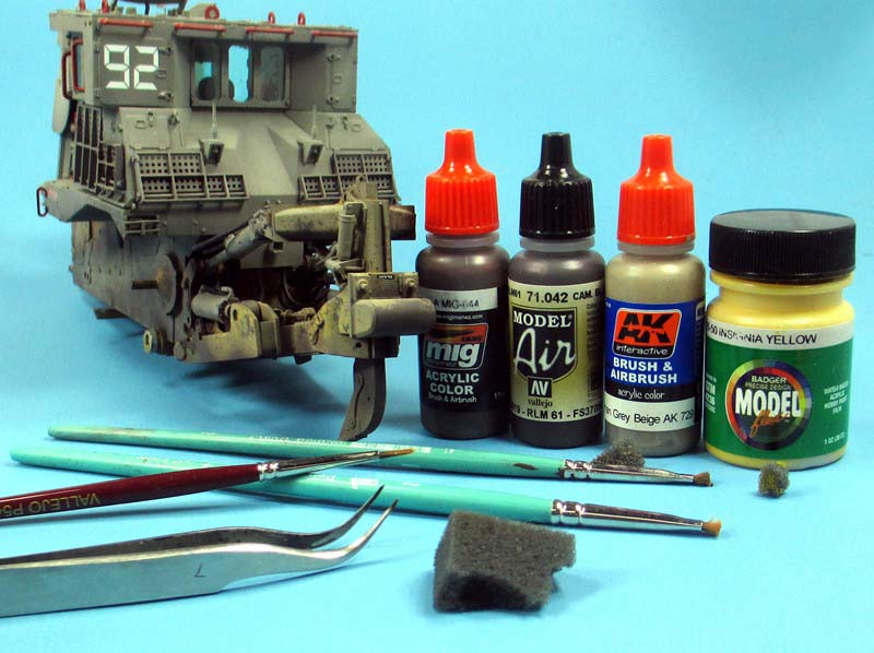


About the Author


FROM: MASSACHUSETTS, UNITED STATES
I am building what I like, when I like and how I like it; having fun doing it. I have been building and finishing models on and off my whole life but the past ten years things really exploded. Just about anything goes when it comes to hitting the bench, but wrecked armor, rusted hulks, ships or ...
Comments

Of course, your WIP photos completely disprove my theory, but it's a phenomenal piece of work
MAY 01, 2014 - 08:10 PM

Thanks again Mark!! Sorry to disband any "theories" there were!!
Thanks Bill! Aside form the numerous pictures of these things completely covered in dust there are plenty of interesting shots where the sandy mess seems to collect in a few spots leaving the rest, well...not. I was looking at some pics of these in the Golan Heights and the dark brown mud was very enticing... Maybe next time!!
MAY 02, 2014 - 02:50 AM

Sorry about that. I have a question. In step 5 there is a some small/big screws in spruce A that needs to cut in a different way, but where those screws goes to? The instructions doesn't specified where. I think there is another step that mention the same thing. Any help? Thanks!
JUL 20, 2015 - 07:46 PM
Hello Jose,
Yeah, the instructions are a bit shady in that section. In step 5 there is to small graphics at the top...one square and one round....the square one is correct, the round is not. The bolt heads are to be installed on the backside of the cylinders...facing the ripper. there are two different sizes.
In this picture you can see where they go. I found it easier to make my own bolt heads, this is why they are white in the picture.
 Also, I added some bolt heads to the large piston for the dozer blade! Hope this helps....have fun!!
Also, I added some bolt heads to the large piston for the dozer blade! Hope this helps....have fun!! JUL 20, 2015 - 08:30 PM
Thanks for the tip! I assumed that is the same procedure for step 37 also. Can't wait till painting, but I'm little concern about the tracks when I get to that step.
JUL 21, 2015 - 07:48 PM
How did you make the bolts? You right! Was hard for me to cut a nice one.
JUL 22, 2015 - 02:54 AM
In step 26 Tracks assembly, parts A5 and A6 is state use to finish the whole track. What they mean about that? I didn't see those parts in your pics unless you painted them black after finished the track. Also, do I supposed to punch a hole in part C2 to connect the link with C1?
JUL 23, 2015 - 02:32 AM
Hello Jose,
Sorry for the delay. I am away at the IPMS Nationals in Ohio.
The bolt heads were made using the RP TOOLZ Hexagonal punch and die set.
As for the tracks, the written English in the instructions is a bit off. I have to assume they were meaning you need to finish the construction of the tracks. They are not too bad once you get going. No, you do not need to punch anything out. If you take the side with the post on it and lay it down so the post is sticking up, slide the next link over the post and attach the non-posted link to the top of the post via thin cement or CA. I put a tiny drop with a small paint brush on top of the post carefully and then place the small flat link on...the open end will slide down over the next post.....and so forth. I would go out about 10 links and then set that aside to dry and start another run.
When I finished the 10, then I would put the track pads on after letting them sit for maybe 10 or 15 minutes.
If don correctly...and the glue is on top of the post the links will be working. Like I said...it get easier once you start.
Best of luck!
JUL 25, 2015 - 03:10 AM
Copyright ©2021 by Todd Michalak. Images and/or videos also by copyright holder unless otherwise noted. The views and opinions expressed herein are solely the views and opinions of the authors and/or contributors to this Web site and do not necessarily represent the views and/or opinions of Armorama, KitMaker Network, or Silver Star Enterrpises. All rights reserved. Originally published on: 2014-05-01 12:47:58. Unique Reads: 20254

WEB HOSTING BY


Copyright ©2021 Armorama and Kitmaker Network, a subsidiary of Silver Star Enterprises
All Rights Reserved. Please read our Conditions of Use and Privacy Policy.
All Rights Reserved. Please read our Conditions of Use and Privacy Policy.