1⁄35Building the Dragon 251/17 w Schwebelafette
16
Comments

Stage 5
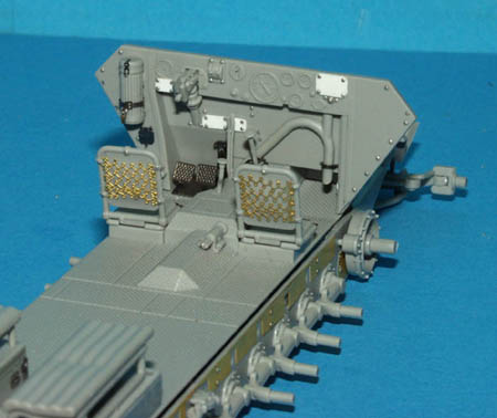
This stage concerns itself with the construction of the drivers’ compartment, and rear benches in the fighting compartment. In addition to the nice set of photo etched parts that Dragon supply with this kit, I was also using the generic 251 D set from Eduard, set number 35 831. The Eduard set contains a lot of useful parts, including the full dash for the 251, which in this case I had decided not to se, but I did install the bracket for the gas mask cylinder, a small electrical socket beneath this, a really nice set of foot pedals, brackets for the heating duct, two nice floor panels with pull handles, and a base for the gear shift stick. Whilst building the crew compartment I also decided to improve it with some rivets that were missing, and a also to place a few missing data plates on the dash. Dragon supply the wonderful photo etched springs for the seat backs, and also the option of covering these with photo etched map cases. At least I think they’re map cases, and Eduard supply you with two also, however, I couldn’t bring myself to cover up those lovely springs! Eduard have also supplied hinges and some extra detail for the storage boxes underneath the benches. When all this detail has been installed then it’s time for fitting the floor to the lower hull. The positioning of this is critical. Get it wrong and it will throw off the entire hull later. From experience, I know that it is possible to get an absolutely perfect join between the upper, lower, and rear hulls, and that this is where it can all go wrong. As mentioned earlier, I didn’t use any of the supplied bits and pieces for underneath the floor, but I did put a few sheets of lead, simply to give the model that ‘weighty’ feel! When you place the floor onto the lower hull, there are 3 small tabs that fit into recesses on the lower side of the floor. To ensure perfect alignment, make sure that the hull is perfectly central, and that the gap down either side between the floor and the hull is the same size. These gaps are used to ‘click’ into place the hull sides later in the build, and if the floor is not central, one or the other will prove impossible.Stages 6, 7, 8, 9 & 10
These 5 stages prepare the lower hull sides, the rear, and the drivers’ and co-drivers’ vision slots. As in all the Dragon 251 kits, the molds are generic, and as such have all the location marks on them for all the different versions. It pays to go through these stages and remove all the marks you will not need for this version. There are a couple of injector pin marks, but these will not be seen once the walls are in place. I again added some rivet detail that was missing, and also the Eduard replacements for the MP40 machine pistol brackets, the ammunition cases beneath each of these, and some miscellaneous brackets. Stage 8 is the construction of the ammunition boxes for storing the 2cm magazines. Each of these has been constructed so that up to 4 magazines can be left out if desired, or filled up with magazines that are supplied. Be warned though, that the magazines that are supplied to fill these gaps are very slightly different in detail to those that are molded in, and look very different too, so with this in mind I later removed the two I had installed. I replaced the fir extinguisher on the rear wall with the Eduard bracket, and also attempted to replace the wall stowage lockers behind the seat brackets. The Eduard replacements are wrong however, and required the removal of two small pieces from each bracket to make more accurate. The drivers’ and co-drivers’ vision blocks are supplied as transparent styrene, along with all their associated brackets. I used to have trouble assembling these, bt I thin I have the knack of them now. I begin by cementing part W3 to W2, then W1 to W5. Insert the W3/2 part through the opening, and then attach part W1/5. There is a tendency to try and make this last part sit flush, but it should only do that if the vision slot is open. Otherwise, it should project at an angle, which is not shown clearly on the instructions. When everything is ready, it’s time to install the lower hull walls onto the chassis. As mentioned before, each side wall should click into place between the floor and the chassis. It is a very tight fit though! Hold the side wall almost horizontal, force it into the gap and then raise into position. Each side wall should remain in position almost by itself. Once you have each one in, they have to be aligned properly to prevent later problems fitting the upper hull. I’ve tried aligning the ‘V’shape at the front of each wall, and this does not give proper alignment. For a perfect alignment I have found that it is far better to match up the small rectangular recess above each of the front wheels. Once you have this achieved, run some very thin styrene cement along the join from the outside, and also along the inside at the edge of the floor and this should be sufficient to fix each wall in place.Comments
Vinnie:
Another great build and an excellent article. You are a modelling machine. :-) Cant wait to build a 251
JAN 20, 2006 - 09:46 PM
As always Vinnie, your reviews are written excellent, informative and filled with great detail. You are most definitely a building machine! Thanks!
JAN 20, 2006 - 10:06 PM
Hi Vinnie, absolutely superb, but I am already itching to buy yet another 251 now once they get into the shops here.
I forsee another chastising from the wife.
John
JAN 20, 2006 - 11:41 PM
Thanks guys. Dan, thanks for working with Dragon to produce another brilliant 251! As for the etched shield, I thought I was going to have problems too, during the early stages, but if the instructions are followed carefully, then it lierally falls into place.....beautifully designed. Thanks again!
Vinnie
JAN 22, 2006 - 11:41 AM
Yet another great model build from you Vinnie.
I read the article about the 250/16 flammpanzerwagen and bought one your myself and build it, will post it soon. But did not turn out as good as your master piece.
:-) :-)
JAN 22, 2006 - 03:20 PM
Hi Vinnie,
very nice model and very interesting article! Really.
Only a question. Can you tell me your technique to make rivets... they're so realistic. In the article you spoke of Nutter and Small Shop, have you some pics or link??
Thanks
Tom
JAN 22, 2006 - 04:30 PM
Fantastic build review, Vinnie. Excellent work, and a super step-by-step view of the assembly stages. Truly amazing, my friend.
I got these 2cm Schwebelafette halftrack kits in a few weeks ago, and I have considered getting one, but I think I will stick with the Dragon Sd Kfz 251/21 Ausf D Drilling I already have. Then again, seeing yours may change my mind !
You should have your own homepage, or website gallerie of all your work and reviews, if you dont already have one !
Thanks for posting
Cheers !!
Alpen
JAN 23, 2006 - 06:57 AM
Great review and build Vinnie. I always enjoy reading your articles.
~Martin
JAN 23, 2006 - 08:31 PM
Copyright ©2021 by Vinnie Branigan. Images and/or videos also by copyright holder unless otherwise noted. The views and opinions expressed herein are solely the views and opinions of the authors and/or contributors to this Web site and do not necessarily represent the views and/or opinions of Armorama, KitMaker Network, or Silver Star Enterrpises. All rights reserved. Originally published on: 2006-01-20 00:00:00. Unique Reads: 30588


