

Hosted by Darren Baker
Sdkfz 250/1 Neu Premium Blog

wbill76

Joined: May 02, 2006
KitMaker: 5,425 posts
Armorama: 4,659 posts
Posted: Saturday, November 24, 2007 - 06:44 PM UTC
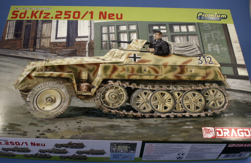
Build log thread for DML's kit #6427 Sdkfz 250/1 Neu Premium Edition. More updates to come as the build progresses.
wbill76
Joined: May 02, 2006
KitMaker: 5,425 posts
Armorama: 4,659 posts
Posted: Sunday, November 25, 2007 - 03:14 PM UTC
Work began where it usually does, at Step 1! This step is a very simple step, it installs the sprocket drive housings, parts H3/H6, to the hull tub.

I skipped Step 2 since that deals with the installation of the suspension arms and the idler arm. Test fits showed just a little bit of play in the arms so to avoid issues when the tracks are constructed, they will be installed later.
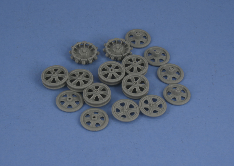
Step 3 deals with all of the road wheels and the sprockets. The sprockets are 3 part assemblies and each part has 4 connection points, so care is needed when removing from the sprues. The insert, G3, needs to be installed to H2 first to avoid problems and I used locking tweezers to slowly clamp each of the rollers together 2 at a time using liquid glue. The idler pair, parts G20/G4, are different from the standard road wheel pair in that G20 has a larger hole, so I marked these on the back with a Sharpie to insure I don't get them mixed up later on. The contact pins for the road wheel halves are tiny and not very helpful in keeping alignment, so I went slow through this part and made sure each wheel set was aligned properly before moving on to the next one.
Steps 4 and 5 deal with the installation of the wheels and the tracks, both of which were skipped. However the base for the steering rod, A8, was installed. Step 6 deals with the main part of the front wheel suspension and consists of 4 parts. All of these are from the older mold and need a bit more clean-up on seam lines as a result. The suspension is not workable/positionable without alteration, so I assembled parts A1, A4, and A5 together first and then glued them into the lower hull before attaching the Y-shaped brace part A6.

Step 7 adds some additional suspension details in the form of the steering linkage and the tow hooks.

This step also deals with the construction of the front tires and wheel hubs. Each tire is constructed from 5 slices plus the wheel hub and the instructions are misleading a bit here in terms of when the hub needs to be added to the "stack" of slices. It's not possible to keep the wheel hub separate for painting and still construct the wheel since the first two slices need to be attached first.
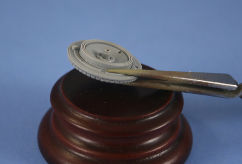
Then the rest of the slices can be added on top of that to construct a very detailed tread pattern. Once all the slices were in place, I ran some liquid glue carefully around the lip of the rim to secure the hub in place.
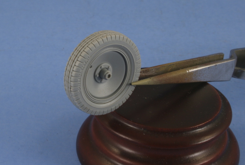
This was repeated for the second tire to complete the step. Later on I'll use a sharp knife point to modify the U on the "Continentau" and see about adding a piece of stretched sprue or something for the missing valve stem for the tires.

Next up will start work on the interior.
I skipped Step 2 since that deals with the installation of the suspension arms and the idler arm. Test fits showed just a little bit of play in the arms so to avoid issues when the tracks are constructed, they will be installed later.
Step 3 deals with all of the road wheels and the sprockets. The sprockets are 3 part assemblies and each part has 4 connection points, so care is needed when removing from the sprues. The insert, G3, needs to be installed to H2 first to avoid problems and I used locking tweezers to slowly clamp each of the rollers together 2 at a time using liquid glue. The idler pair, parts G20/G4, are different from the standard road wheel pair in that G20 has a larger hole, so I marked these on the back with a Sharpie to insure I don't get them mixed up later on. The contact pins for the road wheel halves are tiny and not very helpful in keeping alignment, so I went slow through this part and made sure each wheel set was aligned properly before moving on to the next one.
Steps 4 and 5 deal with the installation of the wheels and the tracks, both of which were skipped. However the base for the steering rod, A8, was installed. Step 6 deals with the main part of the front wheel suspension and consists of 4 parts. All of these are from the older mold and need a bit more clean-up on seam lines as a result. The suspension is not workable/positionable without alteration, so I assembled parts A1, A4, and A5 together first and then glued them into the lower hull before attaching the Y-shaped brace part A6.
Step 7 adds some additional suspension details in the form of the steering linkage and the tow hooks.
This step also deals with the construction of the front tires and wheel hubs. Each tire is constructed from 5 slices plus the wheel hub and the instructions are misleading a bit here in terms of when the hub needs to be added to the "stack" of slices. It's not possible to keep the wheel hub separate for painting and still construct the wheel since the first two slices need to be attached first.
Then the rest of the slices can be added on top of that to construct a very detailed tread pattern. Once all the slices were in place, I ran some liquid glue carefully around the lip of the rim to secure the hub in place.
This was repeated for the second tire to complete the step. Later on I'll use a sharp knife point to modify the U on the "Continentau" and see about adding a piece of stretched sprue or something for the missing valve stem for the tires.
Next up will start work on the interior.

TankTrap

Joined: December 08, 2006
KitMaker: 456 posts
Armorama: 403 posts

Posted: Sunday, November 25, 2007 - 05:12 PM UTC
Thats a cool little thing.
looks like nice kit to.
Im watching this one...


looks like nice kit to.
Im watching this one...
wbill76
Joined: May 02, 2006
KitMaker: 5,425 posts
Armorama: 4,659 posts
Posted: Monday, November 26, 2007 - 07:42 AM UTC
David,
I set the hull tub up against a StuG III I recently completed to see the scale and the guy's definitely on the smaller side. Makes it all that more interesting in my view. Thanks for your interest in the build.
I set the hull tub up against a StuG III I recently completed to see the scale and the guy's definitely on the smaller side. Makes it all that more interesting in my view. Thanks for your interest in the build.

SSJugend
Joined: April 02, 2006
KitMaker: 123 posts
Armorama: 111 posts
Posted: Monday, November 26, 2007 - 09:53 AM UTC
This is going to be one of my next kits after i get done with some paper panzers!!!
Looking good so far!.. This kit needed to be overhauled!
Keep us updated!
Russ
Looking good so far!.. This kit needed to be overhauled!
Keep us updated!
Russ
wbill76
Joined: May 02, 2006
KitMaker: 5,425 posts
Armorama: 4,659 posts
Posted: Monday, November 26, 2007 - 10:46 AM UTC
Thanks Russ, I'm half-way hoping they'll continue with the rest of the 250 series of kits they produced. I've got the older kit in the stash as well and it's easy to see where the improvements were made.

PanzerMike
Joined: May 09, 2007
KitMaker: 298 posts
Armorama: 162 posts

Posted: Monday, November 26, 2007 - 03:47 PM UTC
Great work ! I enjoy reading your build blogs , the pics are always very clear and well explained. I am keen to buy this little gem now as i already have a couple of the earlier 250 kits in the stash including the Stummel.
wbill76
Joined: May 02, 2006
KitMaker: 5,425 posts
Armorama: 4,659 posts
Posted: Tuesday, November 27, 2007 - 08:12 AM UTC
Panzermike, thanks for the interest. If I had to bet, I'd say that the Stummel is the next likely candidate for the "Premium" treatment in the series, something I hope they do.
PanzerMike
Joined: May 09, 2007
KitMaker: 298 posts
Armorama: 162 posts
Posted: Tuesday, November 27, 2007 - 10:21 PM UTC
Thats excellent I shall be keeping an eye out for that when it comes out
I shall be keeping an eye out for that when it comes outwbill76
Joined: May 02, 2006
KitMaker: 5,425 posts
Armorama: 4,659 posts
Posted: Friday, December 07, 2007 - 04:29 PM UTC
Made some progress on the interior, I decided that the best approach is going to be a "modular" one, meaning that I'm going to keep the interior broken down into sub-components as much as possible before painting.
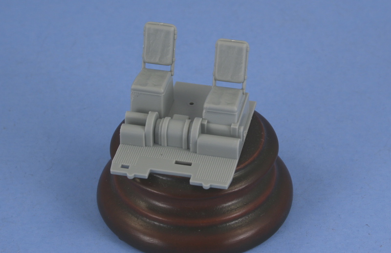
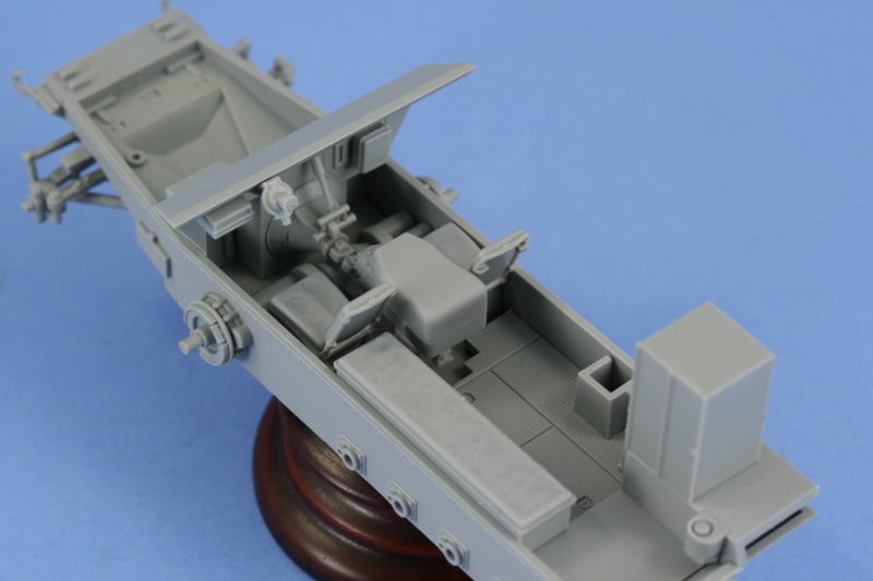
Step 8 deals with the first module, the floor plate and seats for the driver and commander. The floor plate is one piece and the seats are two pieces, one for the seat itself and the other for the back rest. These installed easily enough, just a little care needed to get the tabs seated all the way into the bases with some liquid glue. This step also calls for the plate to be installed into the lower hull but I've held off doing that just yet.
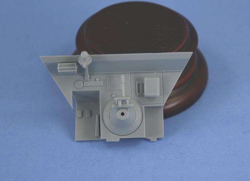
Step 9 deals with the firewall for the driver's compartment. I installed all of the parts except the steering wheel, this will be painted separately and then installed. The details here are somewhat basic with the foot pedals just square representations and the gear shift lever is on the simplified side of things.
Step 10 deals with the rear compartment plate and various details. The locker for the MG ammo is a two piece assembly with the doors attached directly to the box in the closed position. The fuel filler cap is added to the rear and the long bench seat for the left side is also assembled and installed. Attached to the side of the ammo locker is the spare MG barrel holder and MG toolkit container, although looking at interior reference photos it looks as if the part has these reversed but it's not a huge thing considering. Last but not least, two holes need to be opened up in the right side of the floor to take the pedestal mount for the extra seat. Take care when doing this as the holes need to be big enough for the mount but not too big as the edge of the pedestal base isn't very wide to begin with. The seat itself is a two part assembly like the driver/commander seats and I used a bit of blue tack to dry-fit it in place to be sure it would clear the MG case behind it.

Next up will be the compartment sides, which ought to be a lot of fun as this is where much of the "premium" treatment gets applied.
Step 8 deals with the first module, the floor plate and seats for the driver and commander. The floor plate is one piece and the seats are two pieces, one for the seat itself and the other for the back rest. These installed easily enough, just a little care needed to get the tabs seated all the way into the bases with some liquid glue. This step also calls for the plate to be installed into the lower hull but I've held off doing that just yet.
Step 9 deals with the firewall for the driver's compartment. I installed all of the parts except the steering wheel, this will be painted separately and then installed. The details here are somewhat basic with the foot pedals just square representations and the gear shift lever is on the simplified side of things.
Step 10 deals with the rear compartment plate and various details. The locker for the MG ammo is a two piece assembly with the doors attached directly to the box in the closed position. The fuel filler cap is added to the rear and the long bench seat for the left side is also assembled and installed. Attached to the side of the ammo locker is the spare MG barrel holder and MG toolkit container, although looking at interior reference photos it looks as if the part has these reversed but it's not a huge thing considering. Last but not least, two holes need to be opened up in the right side of the floor to take the pedestal mount for the extra seat. Take care when doing this as the holes need to be big enough for the mount but not too big as the edge of the pedestal base isn't very wide to begin with. The seat itself is a two part assembly like the driver/commander seats and I used a bit of blue tack to dry-fit it in place to be sure it would clear the MG case behind it.
Next up will be the compartment sides, which ought to be a lot of fun as this is where much of the "premium" treatment gets applied.

DT61

Joined: September 18, 2005
KitMaker: 1,226 posts
Armorama: 819 posts

Posted: Friday, December 07, 2007 - 11:35 PM UTC
Bil,
Great build blog and I am looking forward to seeing it completed. The 250 series have always been a favorite of mine.
Darryl
Great build blog and I am looking forward to seeing it completed. The 250 series have always been a favorite of mine.
Darryl

ti

Joined: May 08, 2002
KitMaker: 2,264 posts
Armorama: 1,763 posts
Posted: Saturday, December 08, 2007 - 12:41 AM UTC
I do not know how you get your pics so crisp but I like it.  What camera and setup are you using?
What camera and setup are you using?
wbill76
Joined: May 02, 2006
KitMaker: 5,425 posts
Armorama: 4,659 posts
Posted: Saturday, December 08, 2007 - 03:55 AM UTC
Thanks Daryl, the 250 and 251 series have always fascinated me too, I've built one of DML's older 250 kits previously, the /10, so it's interesting to see what they changed in this one vs. the older kits.
Charles,
For my photos, I use a Canon Rebel XTi 10 megapixel Digital SLR camera with the standard lens for WIP shots, sometimes resorting to a 60mm Macro lens for the smaller details. The camera is only the first part of the equation though, what makes it possible is the photo booth setup that I've got. I use a light tent with 4 different adjustable light sources and a light blue background (camera favors that color over white or light gray). I also use a tripod and a remote mechanical trigger to avoid camera-shake when taking the photos.

Plasticbattle

#003

Joined: May 14, 2002
KitMaker: 9,763 posts
Armorama: 7,444 posts

Posted: Saturday, December 08, 2007 - 04:20 AM UTC
Quoted Text
Great work ! I enjoy reading your build blogs , the pics are always very clear and well explained.
Same here and for the same reason. Great work again Bill. Glad to see you back and building again! Have never built a 250, and must say this has me very tempted. Love the detail on the front tyres. Will be watching.


wbill76
Joined: May 02, 2006
KitMaker: 5,425 posts
Armorama: 4,659 posts
Posted: Saturday, December 08, 2007 - 03:55 PM UTC
Thanks Frank, appreciate the comments and interest.
Here's the latest:
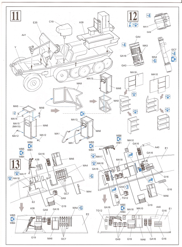
Continuing on with the interior today, I skipped Step 11 as that calls for the installation of all the interior sections into the lower hull. Steps 12 and 13 deal with the new interior layout for the two different sides.
As a result of this being a "Premium" edition, the hull side panels have a mix-and-match set of molded in placement lines, some of which are appropriate for this kit and others left over from the older release. Why DML went through the trouble of adding new molded in locater guides but didn't remove the old ones is somewhat of a mystery, but that's the way it is on both sides of the hull. The newer locater marks overlap the old ones in many places as a result.
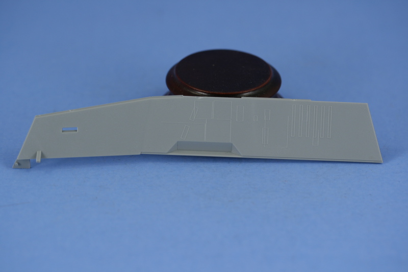
I started with the left hull side first, removing all the un-needed mold lines from the old kit as well as the new ones that were added for the large PE box that goes roughly in the middle according to the instructions. This box doesn't belong to a /1 variant, it belongs to the /5 spotting variant and since it won't be installed, the mold lines also went.
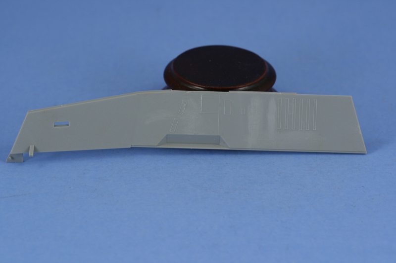
The right side required more surgery since it had molded on heavy mount points for the right side stowage bin not present on the Neu as well as a curved mount point that was a holdover from the older kit.

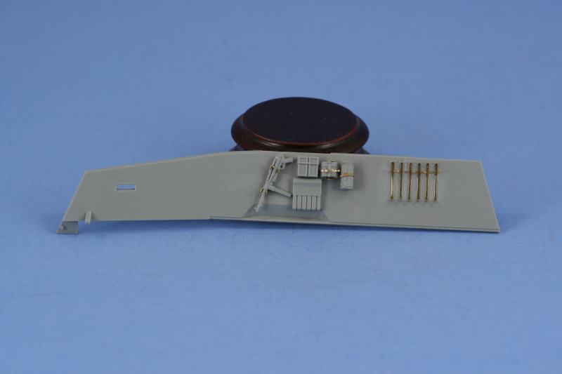
Once that was taken care of, I started in adding the details for the left side. The "premium" treatment here deals primarily with the addition of PE mount brackets and Gen 2 crew gear. Curiously, the MP38s provided in the added WA sprue are not identical...one has the folding stock molded in place and the other has the folding stock as a separate piece...and they both have different receiver/bolt mechanisms, one that is in the charged position and the other not...and although the instructions indicate you have a choice with the double arrows, only one of each is provided so your choice is really which one goes on which side!
The brackets for the MP38s are provided as PE and the instructions aren't very helpful in how to bend them to the necessary shape as they show them already installed, however after some study I was able to figure it out. The PE brackets are not the same size as the molded on locater positions, being somewhat shorter, so testing their respective positions just forward of the trigger and just forward of the magazine is essential to get their placement correct.
Fitting the brackets to the mess tins is a real pain...the Gen 2 tins have prominent features molded on them top and bottom and their little "ear" handles off each side make it an adventure to get the straps and brackets to line up properly. The little PE buckle portions that are on these were so fragile that they broke off with the slightest bit of pressure...a shame they weren't a bit more sturdy as they were a nice added detail. Last but not least, I added the stick grenade brackets one at a time starting at the rear and working my way forward. The instructions indicate only to fill 4 of the 6 brackets since the added GC sprue only has 4 "standard" grenades, although 4 additional are provided of a type I'm not familiar with. These are the normal grenades plus some sort of projection added to the "can" at the end of the stick, these however are too long to fit the brackets, so unless you have grenades from another kit to use, 4's the limit as provided. I carefully bent the clips so that the grenades could be added later after the panel has been painted.
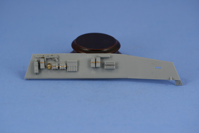
Next up came the right side. This one has a bit more gear than the left side. I gave the PE signal flag racks, MA10 and MA18, a try but while their one-piece design was innovative, the tiny connection points for the little trays proved to be my undoing. Since these have to be shaped in a curve, I annealed it and as I was working on shaping the curves, the entire thing literally fell apart in my hand. The PE is too springy without annealing to shape the curve, so it's a Catch-22...and mine won't have this feature in the end. I'm not 100% sure it belonged to the /1 vs. the /5 to begin with, but wanted to give it a shot to see how they would assemble.
Just as with the left side, the various crew kit items were constructed and installed. I ran into a small problem with the three-in-a-row mess tin holders...due to the dimensions of the Gen 2 mess kits, it's not possible to fit 3 of them into the space designated and still be able to fit the gas mask and fire extinguisher as well as have the necessary room for the MP38 magazine that sticks down...so my novel solution was to install the third kit bracket empty. I also ran into a slight problem with the MP38 for this side, the one with the folding stock molded on...turns out the mount brackets aren't wide enough to fit around the folded mount in position, so some careful trimming with the hobby knife was necessary here as well.
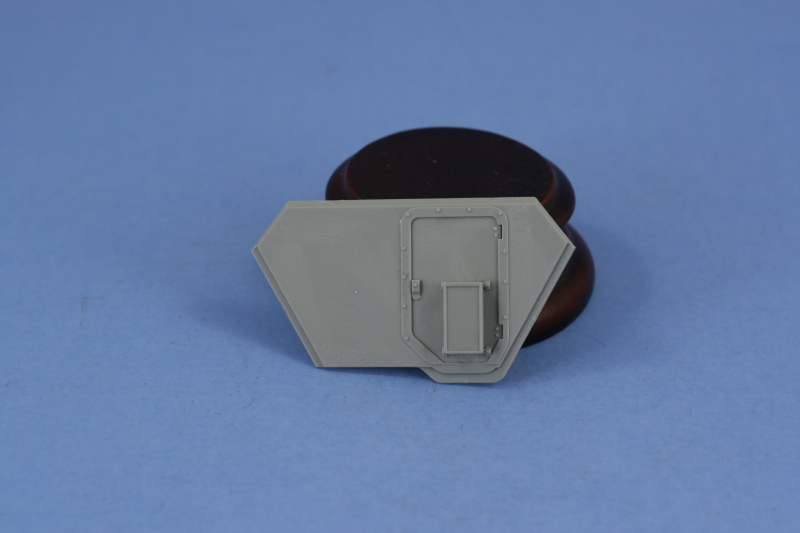
The day's adventures didn't stop there...but a little calm before the next storm. I skipped over Step 14 since that installs the side panels to the hull as well as Step 15 which deals with the side fenders. Step 16 was largely skipped as well except for the construction of the rear hull panel and installation of the crew hatch door. The interior face of the panel and the door had slight raised sink marks that needed to be dealt with but these were very faint and just a small bit of sanding was all that was required. The door was installed in the closed position.
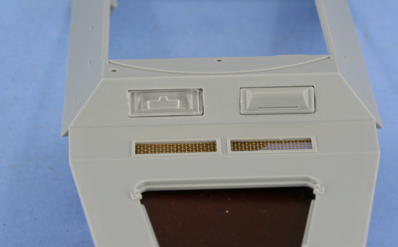
Staying with the interior prep work, next up was the upper hull. I installed the PE grills for the engine intake vents, a much improved area vs. the old vinyl mesh for sure. Other odds and ends details were also installed, except for the crew water bottles, as needed. When it came time to do the driver/radio operator visors is when the fun started. The "premium" package includes the now-familiar clear multi-part assembly for the visors, armored glass, and interior frames that allow for the visor to be posed open or closed on the 251 family of vehicles. As I went to test fit these before installation, I noticed a curious thing...the visors were too small vs. the openings in the hull plate. Since I have the older release kit in the stash, I pulled that out and compared the new clear visors to the old kit ones and sure enough, the older kit visors were larger.

Now the side-by-side difference may not seem like much, but it makes a huge difference when installing these as the frames that support them are the same dimensions...meaning that there's a noticeable gap around the perimeter if you use the supplied clear styrene parts. The "premium" kit still includes the parts on the sprue, E28/E29 and marked as not for use, that are the old kit armored glass/frames housings but the "premium" sprues DO NOT include the old visors. Fortunately, the old kit has 4 visors on the B sprues and only 2 are needed, so I snagged those for use on the "premium" kit. When the older parts are installed, they fill the cutout as they should. Just to highlight the difference, I placed the clear visor on the left over the kit backed frame to show just how much of a size difference there is. It would be possible to use sheet styrene and "fill" the cutouts to make up for this but it would produce a slightly off-center look to the visors unless you did it evenly on either side...a real pain given how small the total difference is. My only conclusion is that DML assumed that the visor dimensions would be the same on the 250 kit as on the 251s that these were originally designed for...and they aren't. You might be able to get by with installing both of the visors in the open position but I had a hard time installing the frames due to the size difference in the first place which is how I discovered the discrepancy so a gap would still likely be present to be dealt with.
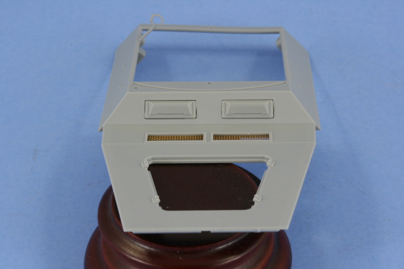
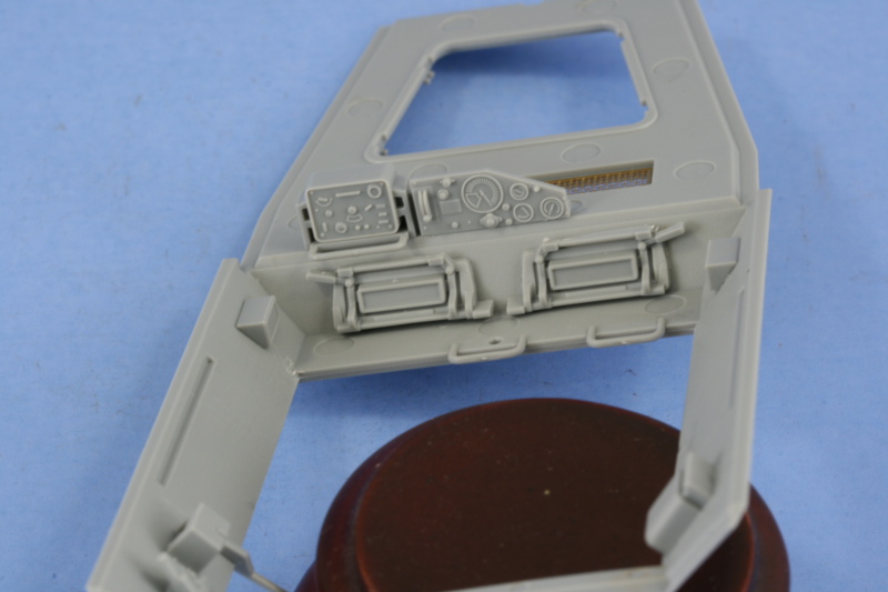
To round out the upper hull details, the instrument panel and radio were installed. These have nice molded on features that ought to make it easier to hand-paint their details. No instrument face decals are provided as in the 251 kits, so that's the only option for this area, but not a hardship really, just an observation.
Here's the latest:
Continuing on with the interior today, I skipped Step 11 as that calls for the installation of all the interior sections into the lower hull. Steps 12 and 13 deal with the new interior layout for the two different sides.
As a result of this being a "Premium" edition, the hull side panels have a mix-and-match set of molded in placement lines, some of which are appropriate for this kit and others left over from the older release. Why DML went through the trouble of adding new molded in locater guides but didn't remove the old ones is somewhat of a mystery, but that's the way it is on both sides of the hull. The newer locater marks overlap the old ones in many places as a result.
I started with the left hull side first, removing all the un-needed mold lines from the old kit as well as the new ones that were added for the large PE box that goes roughly in the middle according to the instructions. This box doesn't belong to a /1 variant, it belongs to the /5 spotting variant and since it won't be installed, the mold lines also went.
The right side required more surgery since it had molded on heavy mount points for the right side stowage bin not present on the Neu as well as a curved mount point that was a holdover from the older kit.
Once that was taken care of, I started in adding the details for the left side. The "premium" treatment here deals primarily with the addition of PE mount brackets and Gen 2 crew gear. Curiously, the MP38s provided in the added WA sprue are not identical...one has the folding stock molded in place and the other has the folding stock as a separate piece...and they both have different receiver/bolt mechanisms, one that is in the charged position and the other not...and although the instructions indicate you have a choice with the double arrows, only one of each is provided so your choice is really which one goes on which side!
The brackets for the MP38s are provided as PE and the instructions aren't very helpful in how to bend them to the necessary shape as they show them already installed, however after some study I was able to figure it out. The PE brackets are not the same size as the molded on locater positions, being somewhat shorter, so testing their respective positions just forward of the trigger and just forward of the magazine is essential to get their placement correct.
Fitting the brackets to the mess tins is a real pain...the Gen 2 tins have prominent features molded on them top and bottom and their little "ear" handles off each side make it an adventure to get the straps and brackets to line up properly. The little PE buckle portions that are on these were so fragile that they broke off with the slightest bit of pressure...a shame they weren't a bit more sturdy as they were a nice added detail. Last but not least, I added the stick grenade brackets one at a time starting at the rear and working my way forward. The instructions indicate only to fill 4 of the 6 brackets since the added GC sprue only has 4 "standard" grenades, although 4 additional are provided of a type I'm not familiar with. These are the normal grenades plus some sort of projection added to the "can" at the end of the stick, these however are too long to fit the brackets, so unless you have grenades from another kit to use, 4's the limit as provided. I carefully bent the clips so that the grenades could be added later after the panel has been painted.
Next up came the right side. This one has a bit more gear than the left side. I gave the PE signal flag racks, MA10 and MA18, a try but while their one-piece design was innovative, the tiny connection points for the little trays proved to be my undoing. Since these have to be shaped in a curve, I annealed it and as I was working on shaping the curves, the entire thing literally fell apart in my hand. The PE is too springy without annealing to shape the curve, so it's a Catch-22...and mine won't have this feature in the end. I'm not 100% sure it belonged to the /1 vs. the /5 to begin with, but wanted to give it a shot to see how they would assemble.
Just as with the left side, the various crew kit items were constructed and installed. I ran into a small problem with the three-in-a-row mess tin holders...due to the dimensions of the Gen 2 mess kits, it's not possible to fit 3 of them into the space designated and still be able to fit the gas mask and fire extinguisher as well as have the necessary room for the MP38 magazine that sticks down...so my novel solution was to install the third kit bracket empty. I also ran into a slight problem with the MP38 for this side, the one with the folding stock molded on...turns out the mount brackets aren't wide enough to fit around the folded mount in position, so some careful trimming with the hobby knife was necessary here as well.
The day's adventures didn't stop there...but a little calm before the next storm. I skipped over Step 14 since that installs the side panels to the hull as well as Step 15 which deals with the side fenders. Step 16 was largely skipped as well except for the construction of the rear hull panel and installation of the crew hatch door. The interior face of the panel and the door had slight raised sink marks that needed to be dealt with but these were very faint and just a small bit of sanding was all that was required. The door was installed in the closed position.
Staying with the interior prep work, next up was the upper hull. I installed the PE grills for the engine intake vents, a much improved area vs. the old vinyl mesh for sure. Other odds and ends details were also installed, except for the crew water bottles, as needed. When it came time to do the driver/radio operator visors is when the fun started. The "premium" package includes the now-familiar clear multi-part assembly for the visors, armored glass, and interior frames that allow for the visor to be posed open or closed on the 251 family of vehicles. As I went to test fit these before installation, I noticed a curious thing...the visors were too small vs. the openings in the hull plate. Since I have the older release kit in the stash, I pulled that out and compared the new clear visors to the old kit ones and sure enough, the older kit visors were larger.
Now the side-by-side difference may not seem like much, but it makes a huge difference when installing these as the frames that support them are the same dimensions...meaning that there's a noticeable gap around the perimeter if you use the supplied clear styrene parts. The "premium" kit still includes the parts on the sprue, E28/E29 and marked as not for use, that are the old kit armored glass/frames housings but the "premium" sprues DO NOT include the old visors. Fortunately, the old kit has 4 visors on the B sprues and only 2 are needed, so I snagged those for use on the "premium" kit. When the older parts are installed, they fill the cutout as they should. Just to highlight the difference, I placed the clear visor on the left over the kit backed frame to show just how much of a size difference there is. It would be possible to use sheet styrene and "fill" the cutouts to make up for this but it would produce a slightly off-center look to the visors unless you did it evenly on either side...a real pain given how small the total difference is. My only conclusion is that DML assumed that the visor dimensions would be the same on the 250 kit as on the 251s that these were originally designed for...and they aren't. You might be able to get by with installing both of the visors in the open position but I had a hard time installing the frames due to the size difference in the first place which is how I discovered the discrepancy so a gap would still likely be present to be dealt with.
To round out the upper hull details, the instrument panel and radio were installed. These have nice molded on features that ought to make it easier to hand-paint their details. No instrument face decals are provided as in the 251 kits, so that's the only option for this area, but not a hardship really, just an observation.

c5flies
Joined: October 21, 2007
KitMaker: 3,684 posts
Armorama: 2,938 posts
Posted: Saturday, December 08, 2007 - 04:05 PM UTC
Ouch on those visors, too bad since the new ones look so good. Otherwise, the hull sides look great, moving along nicely on this one.

wbill76
Joined: May 02, 2006
KitMaker: 5,425 posts
Armorama: 4,659 posts
Posted: Saturday, December 08, 2007 - 04:59 PM UTC
Thanks James.
To add insult to injury, as I was looking over the sub-assemblies to prep them for painting tomorrow, I was checking out the leather transmission cover that doubles as a rest/stand for the MG34/42 gunner's position and discovered that there's no transmission in the kit to go under the cover. Checking the older release, it too didn't have it but was an item that was included in the 250/10 kit #6139 on it's own little two-part sprue. Since they threw in sprues from other kits, why they left out this important detail is beyond me.
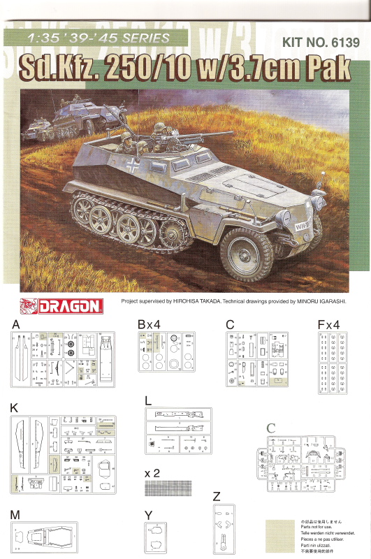
To add insult to injury, as I was looking over the sub-assemblies to prep them for painting tomorrow, I was checking out the leather transmission cover that doubles as a rest/stand for the MG34/42 gunner's position and discovered that there's no transmission in the kit to go under the cover. Checking the older release, it too didn't have it but was an item that was included in the 250/10 kit #6139 on it's own little two-part sprue. Since they threw in sprues from other kits, why they left out this important detail is beyond me.

Hohenstaufen

Joined: December 13, 2004
KitMaker: 2,192 posts
Armorama: 1,615 posts

Posted: Saturday, December 08, 2007 - 06:06 PM UTC
Bill, I'm learning a lot from this blog, which is especially useful as I'm trying to build the same kit. I couldn't understand why the transmission cover had such a long peg on it, so I cut it short & just stuck the thing to the floor! Wrong! Now I can see why the peg is so long, there's supposed to be a tranny under the cover! Great, thanks Dragon. Not having the older kit, I can't rob it for the missing parts. I figured that the hole in the back of the bell housing on the bulkhead should have something connected to it, but when there was nothing in the box, I just shrugged & carried on. I wish I'd waited... The only way out is if the transmission is the same or similar to the Sdkfz251, as I've got a couple lying around from those kits, they go under the floor on the bigger halftrack, so they're never seen, so I've stopped bothering to put them in.
I'm very relieved that the PE boxes & signal flag trays (so that's what they are) aren't needed for a standard 250/1, as mine disintegrated in similar fashion. I don't really like PE, & was a bit dismayed by the amount that came with the kit that seemed to be needed with no options. I've noted what you say about the straps for the accoutrements, maybe I'll cheat & just glue them on without - looks like I'm definitely going to need that tarp supplied in the kit!
I have to say, all in all, that I'm slightly unimpressed by parts of this kit. The missing bits suggest that it was a bit "hurried", which is not what you expect from a "Premium" kit (the price was sure a Premium for such a small vehicle all right!).
From the accuracy point of view, I had already noticed that something else is missing; if you look at parts H3 & H6, you'll see that DML moulded some nice brake shoes on them, which is fine, except there are no drums for them to work in, the sprockets are just installed straight over them! Since I own a couple of old motorbikes, I'm more than familiar with drum brakes, so I spotted this straight away.
Hohenstaufen
Joined: December 13, 2004
KitMaker: 2,192 posts
Armorama: 1,615 posts
Posted: Saturday, December 08, 2007 - 06:17 PM UTC
I managed to get the tranny cover off without too much damage, time to raid the spares box! Sorry, you mean this isn't a vac plastic kit, it's supposed to have all the parts in!?
Thanks for the warning about the visors Bill. I'll have to think about that one. Maybe I have some old Tamiya or AFV Club ones that will fit.
Thanks for the warning about the visors Bill. I'll have to think about that one. Maybe I have some old Tamiya or AFV Club ones that will fit.
wbill76
Joined: May 02, 2006
KitMaker: 5,425 posts
Armorama: 4,659 posts
Posted: Saturday, December 08, 2007 - 06:32 PM UTC
Steve,
 Good idea about the spares for the 251 tranny...I've got several of those around too. If nothing else it at least puts something under the hump...the original release of this kit didn't have the transmission in it. That was the first place I checked to see if there was one and it wasn't there...which is probably why it's an added Sprue Y in the 250/10...they needed to add it to correct that deficiency. Have to admit it left me scratching my head...since the whole point of a "Premium" kit is to upgrade/correct the older kit and bring it up to modern standards. They clearly devoted a lot of attention to upgrading the interior to be more correct for a Neu vs. the Alte...so why they left out the transmission is a mystery...
On the subject of the missing brake drums, that too is an odd one...but at least the sprockets will cover over that one.
Good idea about the spares for the 251 tranny...I've got several of those around too. If nothing else it at least puts something under the hump...the original release of this kit didn't have the transmission in it. That was the first place I checked to see if there was one and it wasn't there...which is probably why it's an added Sprue Y in the 250/10...they needed to add it to correct that deficiency. Have to admit it left me scratching my head...since the whole point of a "Premium" kit is to upgrade/correct the older kit and bring it up to modern standards. They clearly devoted a lot of attention to upgrading the interior to be more correct for a Neu vs. the Alte...so why they left out the transmission is a mystery... On the subject of the missing brake drums, that too is an odd one...but at least the sprockets will cover over that one.

dispatcher
Joined: November 04, 2007
KitMaker: 396 posts
Armorama: 325 posts
Posted: Sunday, December 09, 2007 - 03:27 AM UTC
Bill, I've been following this blog religiously. I purchaced the Dragon kit 6100 & 6102 back over 10 years ago. Never noticed the missing transmission. I quit building the 6100 and never started the 6102 kit. Both kits are nice but I didn't have the time to do a good build on them. Now that I have time I'll give them another try with your blog as a guide.
Joe
Joe
wbill76
Joined: May 02, 2006
KitMaker: 5,425 posts
Armorama: 4,659 posts
Posted: Sunday, December 09, 2007 - 06:02 AM UTC
Joe,
I was lucky in that about a month or so before the Premium kit was announced, I had picked up one of the older releases from Great Models on a sale they had. Glad I did although at the time the Premium was announced I thought I was a victim of Murphy! I have to agree with Steve, it's very disappointing to see that you now need parts from 3 different kits (the old, the Premium, and the 251) to get things to work properly...but at least it's salvagable.
I was lucky in that about a month or so before the Premium kit was announced, I had picked up one of the older releases from Great Models on a sale they had. Glad I did although at the time the Premium was announced I thought I was a victim of Murphy! I have to agree with Steve, it's very disappointing to see that you now need parts from 3 different kits (the old, the Premium, and the 251) to get things to work properly...but at least it's salvagable.
wbill76
Joined: May 02, 2006
KitMaker: 5,425 posts
Armorama: 4,659 posts
Posted: Sunday, December 09, 2007 - 06:03 AM UTC
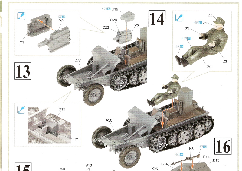
Following on with the discovery yesterday that the kit doesn't have a transmission and after getting a great idea from Steve (thanks Steve!) to use the often supplied tranny from a 251 kit, I dug around in the spares box and assembled one from the spare pieces on sprue C common to all DML 251 kits. They aren't quite the same as the 250 parts that were provided in the 250/10, but it's close enough to fit the bill. The nose pin on the 251 tranny fits perfectly into the housing under the dashboard but will not sit flat on the floor and will "float" a bit. This isn't a big issue necessarily but it does mean that you need a very good join at the nose to avoid it drooping.
The cover/cushion, C19, needs to be modified by having its pin removed, and then can be glued in place carefully over the new transmission. The cover only makes contact at the rear and along the left side, so careful gluing and positioning is key for it to sit properly.
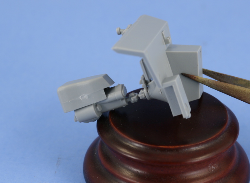
Test fit into the compartment shows that this work-around will do...the cushion still sits just a touch lower than it should, but once the sides and top are in place, it won't be noticeable and is far better than if not used at all. I'll let this dry up good and solid before painting to be sure it doesn't shift around.
The cover/cushion, C19, needs to be modified by having its pin removed, and then can be glued in place carefully over the new transmission. The cover only makes contact at the rear and along the left side, so careful gluing and positioning is key for it to sit properly.
Test fit into the compartment shows that this work-around will do...the cushion still sits just a touch lower than it should, but once the sides and top are in place, it won't be noticeable and is far better than if not used at all. I'll let this dry up good and solid before painting to be sure it doesn't shift around.

biffa
Joined: September 07, 2005
KitMaker: 881 posts
Armorama: 826 posts
Posted: Sunday, December 09, 2007 - 06:39 AM UTC
Looks like your leading the pack with the trouble shooting on this one Bill i too will be building one of these in the near future and am taking plenty of notes, i must say though regardless of the problems you are having it doesnt show in the workmanship, great stuff and hope to see more when you get back from your trip.
Ron.
Ron.


TankCarl
Joined: May 10, 2002
KitMaker: 3,581 posts
Armorama: 2,782 posts
Posted: Sunday, December 09, 2007 - 06:48 AM UTC
Hi Bill.
On my older kit,and this series of 250's,I sub assemble for painting.I leave the firewall and steering wheel as 1 assembly.The front seats as a second. I attach the rear floor into the lower hull (no sides).
And I paint the inner walls of the sides before adding them to the lower hull.
On my older kit,and this series of 250's,I sub assemble for painting.I leave the firewall and steering wheel as 1 assembly.The front seats as a second. I attach the rear floor into the lower hull (no sides).
And I paint the inner walls of the sides before adding them to the lower hull.
 |

WEB HOSTING BY


Copyright ©2021 Armorama and Kitmaker Network, a subsidiary of Silver Star Enterprises
All Rights Reserved. Please read our Conditions of Use and Privacy Policy.
All Rights Reserved. Please read our Conditions of Use and Privacy Policy.