Those taking a more critical look quickly discovered accuracy problems and the praise turned to scorn. Soon, quite a few people were writing off the kit as a useless waste of plastic or, at best, a source for cheap Panzer I tracks. What went so terribly wrong?
The Panzer I Ausf. A, like many tanks, was produced in a series of production runs with each run incorporating changes and improvements. Since the Panzer I formed the core of the very first Panzer Divisions, during a time when serious armored warfare doctrine evolved at a rapid pace, the changes came quickly and in great number.
The first run of Panzer I Ausf. A tanks (Series 1) rolled off assembly lines at the beginning of 1934 without a superstructure. Training units needed vehicles immediately, even though the armored shell remained under development. The second run (Series 2) included the armored shell but operational use revealed certain critical flaws. The third run (Series 3) addressed many of these issues with some upgrades applied to earlier models. The fourth run (Series 4) incorporated yet more improvements. Finally, the whole design was deemed too small and an enlarged version (Series 5 and 6) produced as Panzer I Ausf. B. These began reaching units in late 1936.
DML advertised their Panzer I Ausf. A as an "early" version. The inclusion of the armored superstructure and lack of an interior precludes construction as a Series 1 vehicle.
Series 2 vehicles included these features (kit depiction):
1) For the first 300 vehicles, an extra vision port on the right rear superstructure (correct) *
2) Lacked reinforcing tabs on the 2nd, 3rd, and 4th roadwheels (incorrect)
3) Used a less robust spring for the first roadwheel (incorrect)
4) MG13s with longer barrels (incorrect)**
5) Did not carry a wire cutter on the right front fender**
6) Used the long cylindrical tail light (not sure; cannot remember if the kit includes this part)***
7) Early style horn (correct) ****
8) No superstructure reinforcing strips (correct) *****
9) Two right superstructure vision ports lack vision slit (incorrect)
10) Vision ports do not show three bolts (incorrect)
11) No tab on brake hatch (correct)
12) Narrow brake hatch (correct)
13) Two fuel ports on engine deck (correct)
Two other errors haunt the kit. First, the idler wheels exceed the proper scale diameter by about 1mm. Second, the second and third return roller mounts sit too high on the hull sides by about 1/2mm and 1mm respectively. A beginning modeler can fix many of these issues, but the idler, spring, return roller, and road wheel problems require some effort to correct.
* The remaining Series 2 vehicles match the description above but lack the right rear vision port--another strike against the model.
** Introduced approximately January of 1936.
*** The later style brake light was retrofitted to some Series 2 vehicles.
**** The late style horn appears in late 1935. Panzer Tracts 1-1 implies this occurred during Series 2 production.
***** Superstructure reinforcing strips were introduced during Series 2 production.
Series 3 vehicles included these features (kit depiction):
1) No vision port on the right rear superstructure (incorrect)
2) Reinforcing tabs on all roadwheels (correct)
3) Used a less robust spring for the first roadwheel (incorrect)
4) MG13s with shorter barrels (correct)
5) Wire cutter on the right front fender (correct)
6) Brake light (correct)
7) Early style horn (correct)
8) Superstructure reinforcing strips (incorrect)
9) Right superstructure vision port lacks vision slit (incorrect)
10) Vision ports do not show three bolts (incorrect)
11) Tab on brake hatch (incorrect)
12) Narrow brake hatch (correct) *
13) Two fuel ports on engine deck (correct)
The kit once again misses the mark for a Series 3 vehicle, with the spring, return roller, and idler wheel issues requiring the most work to correct.
* The wide brake hatch was introduced near the end of Series 3 production.
Series 4 vehicles included these features (kit depiction):
1) No vision port on the right rear superstructure (incorrect)
2) Reinforcing tabs on all roadwheels (correct)
3) Robust spring for the first roadwheel (correct)
4) MG13s with shorter barrels (correct)
5) Wire cutter on the right front fender (correct)
6) Brake light (correct)
7) Late style horn (incorrect)
8) Superstructure reinforcing strips (incorrect)
9) Right superstructure vision port lacks vision slit (incorrect)
10) Vision ports show three bolts (correct; some may have the earlier feature)
11) Tab on brake hatch (incorrect)
12) Wide brake hatch (incorrect)
13) Four fuel ports on engine deck (incorrect)
For a third time the kit misses the mark for a Series 4 vehicle, with the brake hatch, engine deck, return roller, and idler wheel issues requiring the most work to correct.
Now, having clarified things a bit up to 1936, the real confusion sets in. Many changes, such as the armor reinforcing strips, reinforced road wheels, late style horn, wire cutter, brake light, and short MG13s were retrofitted to early production tanks! The vision ports also seem to change post production. Past 1936, even more upgrades appear--4 slit convoy lights *, Notek lights *, armored guards over the engine intake and outflow vents*, a smoke candle rack***, late tracks ****, exhaust hose wraps *****, and desert modifications. The kit does not include parts for such late upgrades.
* Introduced in 1939
** Introduced approximately July, 1937.
*** Introduced in 1937.
**** The tracks for this vehicle apparently went through a number of pre-production changes, though the chronology remains unclear to me. Production tracks included small openings in the guide horns. Post production tracks featured solid guide horns.
***** Panzer Tracts 1-1 makes no mention of this feature, but they appear regularly in photos.
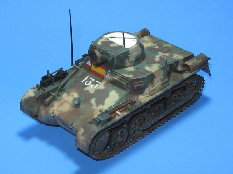
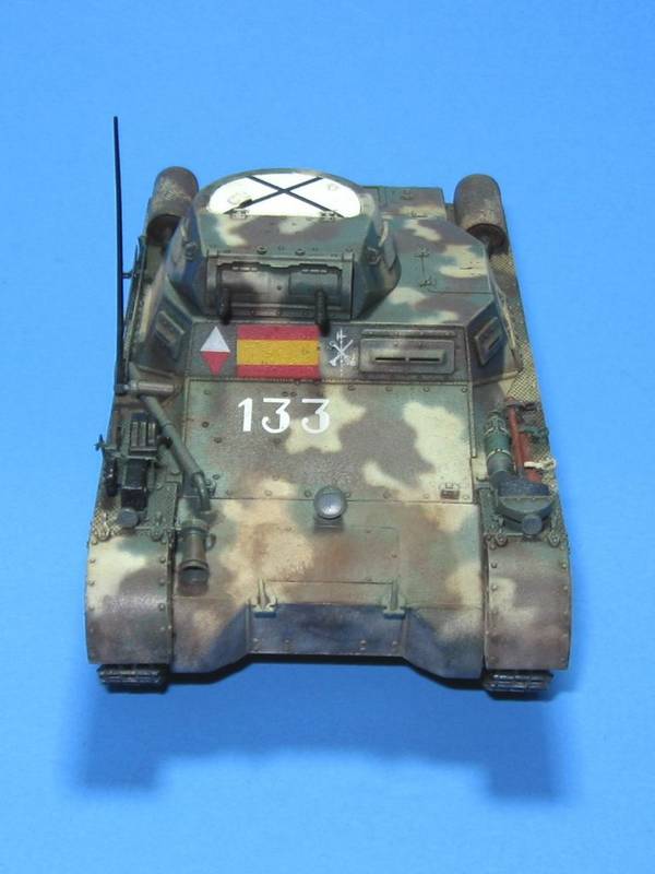
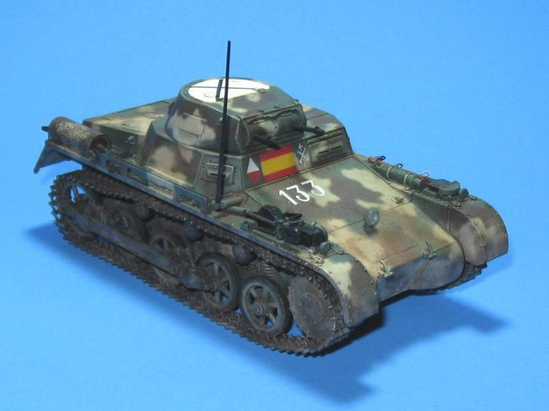
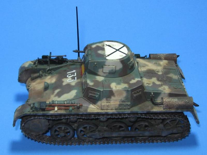
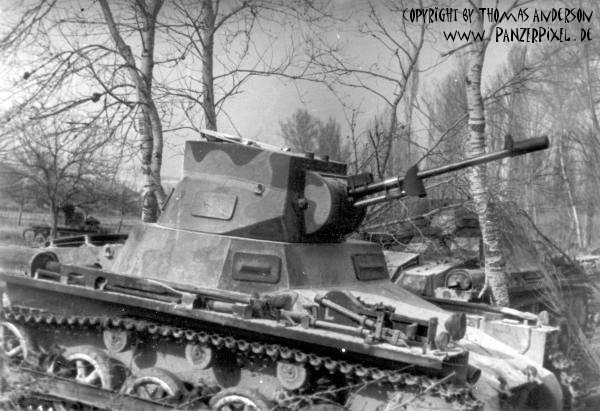
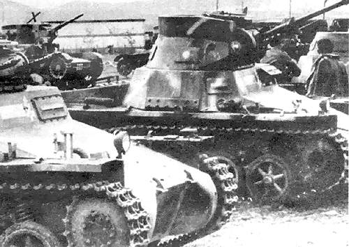
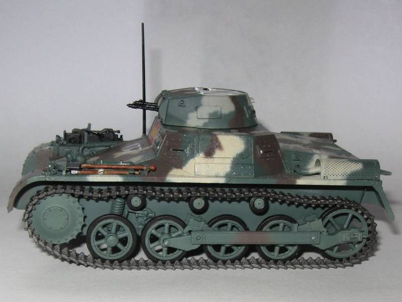
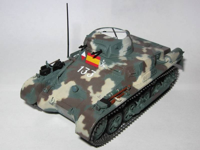
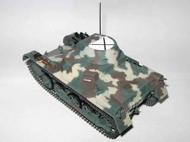
After much consideration I decided to build a 3 Series vehicle as used during the Spanish Civil War. This required correcting the idler wheel, plugging the right rear vision port, adding the reinforcing armor strips to the superstructure sides, and correcting the return roller positions. I forgot to add the tab to the break hatch, decided to leave the front springs along, and learned about the vision port issues too late. No model is perfect.
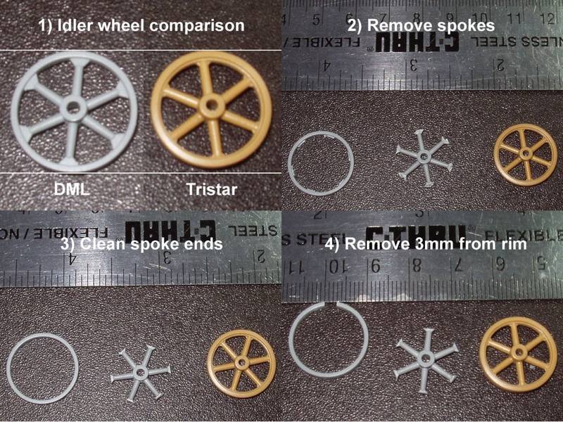
Work began by correcting those pesky idler wheels. Some Tristar and Master Box Panzer IA kits include extras, so check there first. Carefully remove the spoked section of the wheel (Picture 2). Clean up the inner rim of the tire and square off the spoke arms (Picture 3). Remove about 3mm of plastic from the rim of the idler, cutting at a radius (Picture 4).
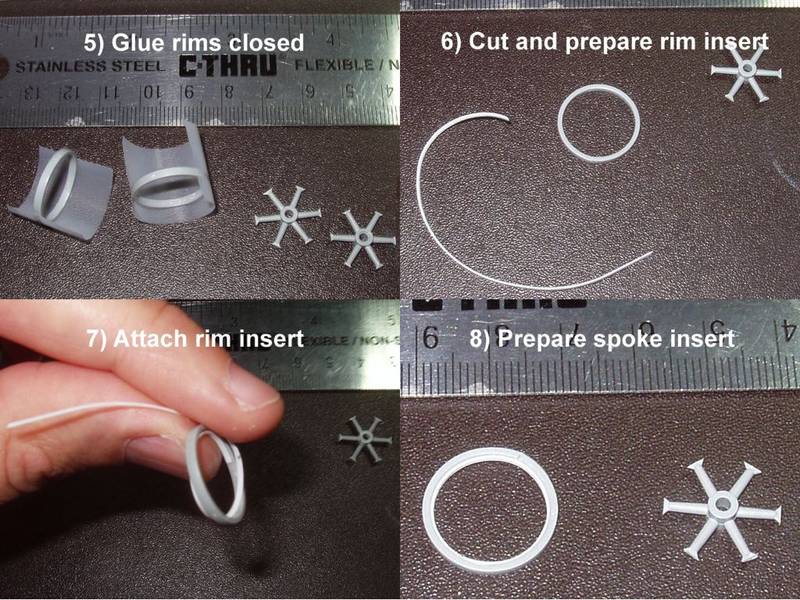
Glue the idler rims together (Picture 5). They should now have the correct diameter. Cut a strip of very thin plastic card about 1mm wide. Use something round and impart a curve to the strip (Picture 6). Glue this to the inner face of the rim, right down the middle, all the way around (Picture 7). Put the starting point of the strip opposite the cut in the rim. Make sure the rim retains a round profile. It may want to deform. Test fit the spoked portion into the smaller idler. Cut away plastic at the end of each spoke EQUALLY until the spoked portion fits snugly inside the rim (Picture 8 ). Glue the spokes in place, along the centerline, with one spoke end at each seam. Optionally, cut off the triangular pieces remaining at the base of each spoke and replace them with larger triangular pieces made from card stock. (I did not perform this step.) Now take the idler wheel inserts and cut away about 1mm. Restore it to a round shape and insert it into the idler. Keep cutting away material from the insert until in fits snugly. Glue it in place with the seam aligned to the seam in the rim. Repeat on the other side. The inserts will butt against the strip inserted down the center of the idler and the spokes. Putty and sand the seam in the idler wheel. During construction, place this seam to the rear of the vehicle under the guide horns of a track link.
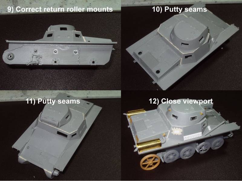
To correct the second and third return roller mounts, draw lines on the hull parallel to the top, bottom, and sides of each mount (Picture 9). Carefully cut off and save the conical portion of each mount. Feel free to cut into the mounting plate but do not cut into the hull. Sand these areas smooth. Cut four 5mm by 7mm pieces of thin plastic card. Round the corners with a file. Square the backs of the conical roller mounts. Draw a straight line on the hull about 1mm below the original top line. Restore the lines previously drawn along the side of each mount. The middle mounting plate goes between the vertical lines, about 1/2mm down from the top line. The last plate goes between the vertical lines, about 1mm below the top line, even with the new line. Place small bolts at the corners of each mounting plate using your method of choice. Glue the conical portion of each mount back in place, at the very center of each plate.
I also added 6 bolts to each side of the hull, where a bulkhead divides the fighting compartment from the engine compartment. Use the corresponding line of bolts on the bottom of the hull as a guide.
Some of the seams around the superstructure require minor putty work (Picture 10). The seam connecting the forward superstructure to the rear superstructure looked a bit too wide so I used some putty there as well. These two assemblies unbolt independently so leave a panel line, not a weld. The spot where the upper hull meets the front plate also requires some putty (Picture 11). The right rear vision port requires a plug (Picture 12).
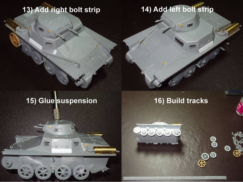
Using plastic card I fashioned the right (Picture 13) and left (Picture 14) armor strips, measuring approximately 4mm by 18mm. Bevel the upper and lower edges at approximately 45 degrees. The DML Panzerbefhelswagen 3 in 1 kit potentially includes extra armor strip parts. Use hex stock of a smaller diameter than shown. (I used what I had.)
I highly recommend gluing the antenna mount in place before installing the brake compartment exhaust vent. If installed in the other order, the vent may interfere with the mount. I was forced to rebuild mine. Place a bolt at each corner of the antenna mounting plate.
To ensure a vehicle with square and flat suspension, I temporarily attached the roadwheels to the bogie arms, glued the bogie arms in place, then let the tank sit flat until everything dried (Picture 15). When finished with this step I removed the roadwheels.
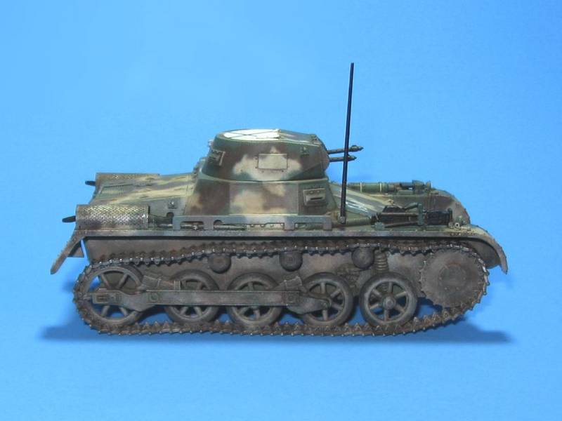
The kit provided Magic Tracks fit very well and require minimal cleanup (Picture 16). I built each track run into a single piece using Testors Liquid Cement. After about 15 minutes, I mounted the track run with the opening in the track positioned at the front of the drive sprocket. Pieces of paper towel inserted between the track and fenders insure the proper sag. After about 24 hours I removed the tracks and wheels for painting.
If such things bother you, make sure to putty the numerous holes in the undersides of the fenders. I also replaced some of the bolts on the sides of the fenders with rod stock. The rest of the vehicle builds up quickly and easily.
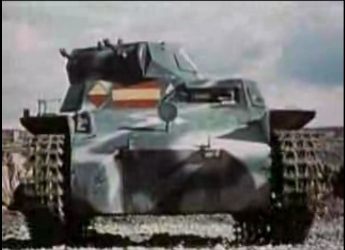
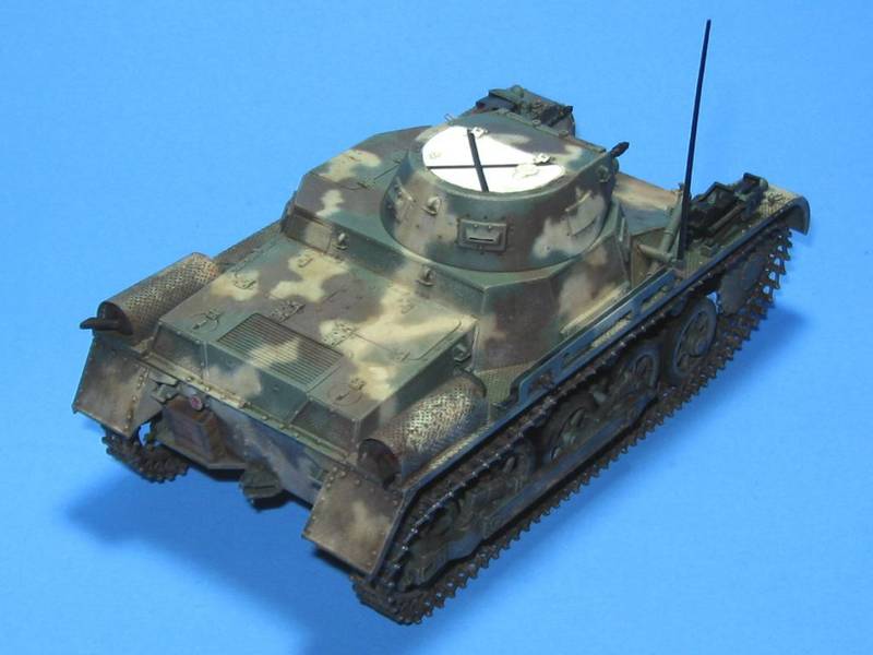
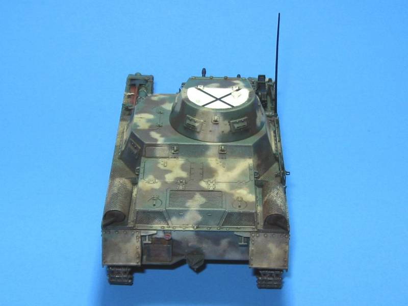
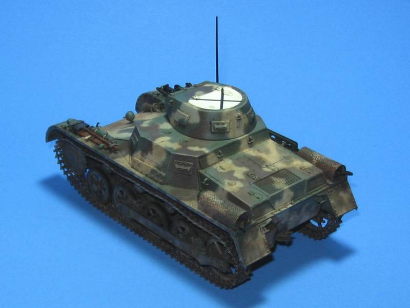
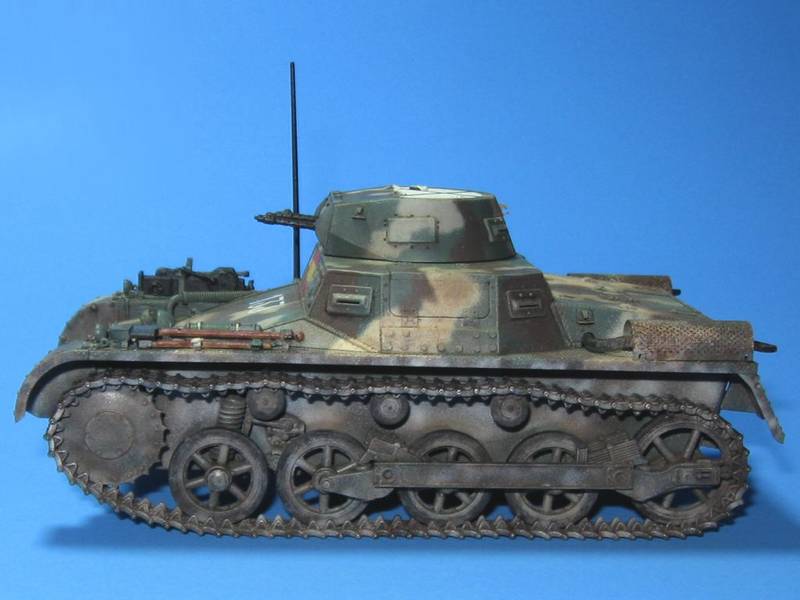
I painted the tank using Model Master enamels based on this photo.
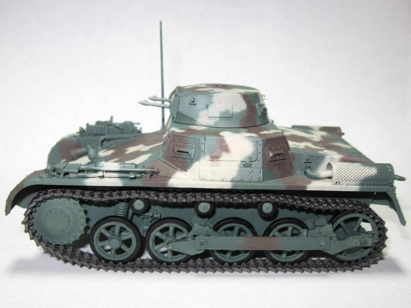
Specifically, I used Panzer Olive Green, Panzer Chocolate Brown, and Armor Sand mixed with a little Panzer Dark Yellow. Tristar's excellent Panzer I Ausf. A Early/Late provided the decals.
Tracks received a coat of Model Master Oiled Steel. MGs, metal tool surfaces, and tires all received Flat Black. Tools received Wood followed by streaks of Raw Sienna or Raw Umber.
My Armor Sand/Panzer Dark Yellow concoction utilized some very old and unreliable paint. The Panzer Olive Green and Panzer Chocolate Brown sprayed much better.
I used Testors Gloss Clear, Semigloss Clear, and Flat Clear acrylics for the clear coats. Photo-etched parts, other than the sheet metal muffler guards, came from a Lion Roar set.
-Doug