Mark, you sick man... lol
damn fine progress mate... just got Mine in yesterday.... still looking for the correct ammo can, but oh well...
the engine is coming along really great... I maybe beg pleade to borrow your plans so I can drop one into Mine some day.
Now if I could just find someone to make 1/16th scale 50's for Me I'd be in hog heaven.
anyways... OUTSTANDING work!!!!!! the brakeline detailing is beautiful.. looking forward to seeing more.
Hosted by Darren Baker
DML 1/4 Ton 4x4 Truck

Rattler

Joined: November 23, 2002
KitMaker: 512 posts
Armorama: 277 posts

Posted: Tuesday, September 14, 2010 - 07:42 AM UTC

sgtreef

Joined: March 01, 2002
KitMaker: 6,043 posts
Armorama: 4,347 posts

Posted: Thursday, September 16, 2010 - 02:24 AM UTC
Kicking butt Mark going to be a real killer indeed.
Rattler looking for 50's in 1/6 scale use the Dragon one.
Cheaper then some others or try the DID one.
Keep at it.
Cheers
Rattler looking for 50's in 1/6 scale use the Dragon one.
Cheaper then some others or try the DID one.
Keep at it.
Cheers

Rattler

Joined: November 23, 2002
KitMaker: 512 posts
Armorama: 277 posts

Posted: Thursday, September 16, 2010 - 10:12 AM UTC
haven't a clue who the DID is... but I'm lookn for 1: 16th scale Not 1/6th... already have the 6th scale 50..
I'm to the point right now of working with an AM company to produce some custom works for Me... since I've had no luck in getting 16th scale 50's
but life goes on though...
I'm to the point right now of working with an AM company to produce some custom works for Me... since I've had no luck in getting 16th scale 50's
but life goes on though...
4444Design

Joined: April 18, 2010
KitMaker: 25 posts
Armorama: 24 posts

Posted: Friday, September 17, 2010 - 12:14 PM UTC
impressive details on your willys!
looking forward to see the progress ...
looking forward to see the progress ...

sgtreef

Joined: March 01, 2002
KitMaker: 6,043 posts
Armorama: 4,347 posts

Posted: Saturday, September 18, 2010 - 12:14 AM UTC
Quoted Text
haven't a clue who the DID is... but I'm lookn for 1: 16th scale Not 1/6th... already have the 6th scale 50..
I'm to the point right now of working with an AM company to produce some custom works for Me... since I've had no luck in getting 16th scale 50's
but life goes on though...
My bad I though I saw 1/16 but answered anyway


So how are those Texas Rangers doing the ones with guns?


Rattler

Joined: November 23, 2002
KitMaker: 512 posts
Armorama: 277 posts

Posted: Saturday, September 18, 2010 - 05:54 AM UTC
lol, wouldn't know bout chuck an his boys.. I stay clear of them chaps LOL
I get in enough troubles with the wife lol
yeah I've got aline of commo going with an AM company about producing some 16th scale barrels, so who knows.. we'll see though.
I get in enough troubles with the wife lol
yeah I've got aline of commo going with an AM company about producing some 16th scale barrels, so who knows.. we'll see though.
plane_mc

Joined: March 25, 2008
KitMaker: 91 posts
Armorama: 90 posts

Posted: Monday, September 27, 2010 - 12:27 PM UTC
I am slowly making progress. I have been working on getting the engine ready to be able to be mounted in the frame. Everything is being held together with posts so I can take it apart as needed to add details.
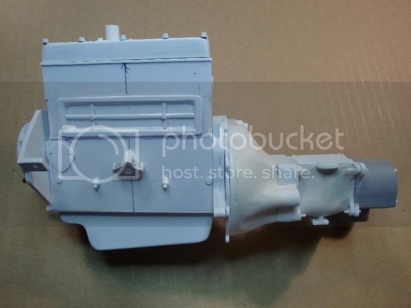
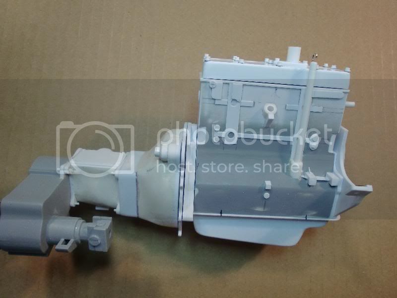
I got the motor mounts and the transmission mount made up and now I can put the whole drive train in the frame. I also made brackets to hold the radiator. This was my first time mocking it up with the wheels and I can honestly say that I am happy with the way things are going.

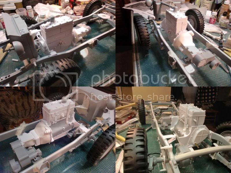
Just for the heck of it, I threw the body on the chassis to see how it was looking.
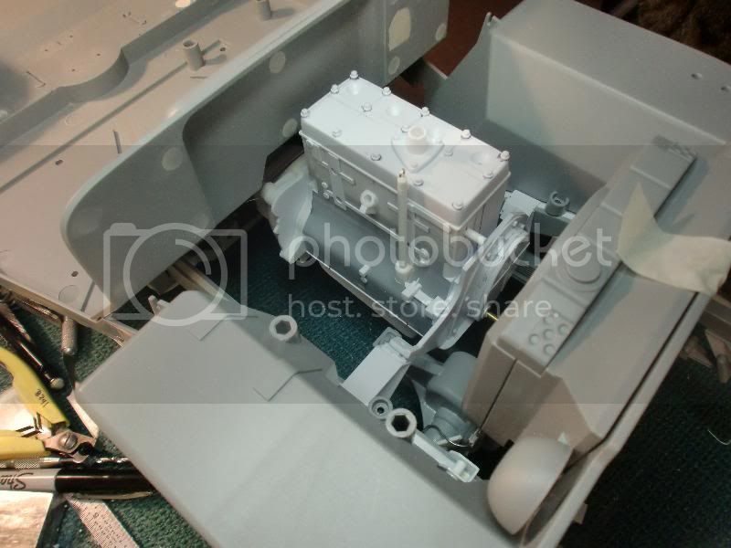
Just a short update today, so thatís all for now, thanks for looking.


I got the motor mounts and the transmission mount made up and now I can put the whole drive train in the frame. I also made brackets to hold the radiator. This was my first time mocking it up with the wheels and I can honestly say that I am happy with the way things are going.


Just for the heck of it, I threw the body on the chassis to see how it was looking.

Just a short update today, so thatís all for now, thanks for looking.
4444Design

Joined: April 18, 2010
KitMaker: 25 posts
Armorama: 24 posts

Posted: Monday, September 27, 2010 - 01:13 PM UTC
Stunning work!
Always checking for the progress and each time you post something new i'm really impressed!
Always checking for the progress and each time you post something new i'm really impressed!

sgtreef

Joined: March 01, 2002
KitMaker: 6,043 posts
Armorama: 4,347 posts

Posted: Tuesday, September 28, 2010 - 12:03 AM UTC
Fantastic work Mark.
Looking better then the resin one that was sold for it.
Can't wait to see more.
Cheers
Jeff
Looking better then the resin one that was sold for it.
Can't wait to see more.
Cheers
Jeff
misharo1971

Joined: August 12, 2009
KitMaker: 18 posts
Armorama: 19 posts

Posted: Tuesday, September 28, 2010 - 04:57 AM UTC
great work so far Mark.
are you going to make some work for wheels?
are you going to make some work for wheels?
plane_mc

Joined: March 25, 2008
KitMaker: 91 posts
Armorama: 90 posts

Posted: Wednesday, September 29, 2010 - 05:13 AM UTC
I don't have anything planned for the wheels other than adding valve stems. I just meant that it was the first time that I had the chassis sitting on the wheels.
plane_mc

Joined: March 25, 2008
KitMaker: 91 posts
Armorama: 90 posts

Posted: Sunday, October 10, 2010 - 03:58 AM UTC
Here is another quick update. I have been steadily working, but it seems like every time I make a step forward, I am having to go back and change something I already did. 
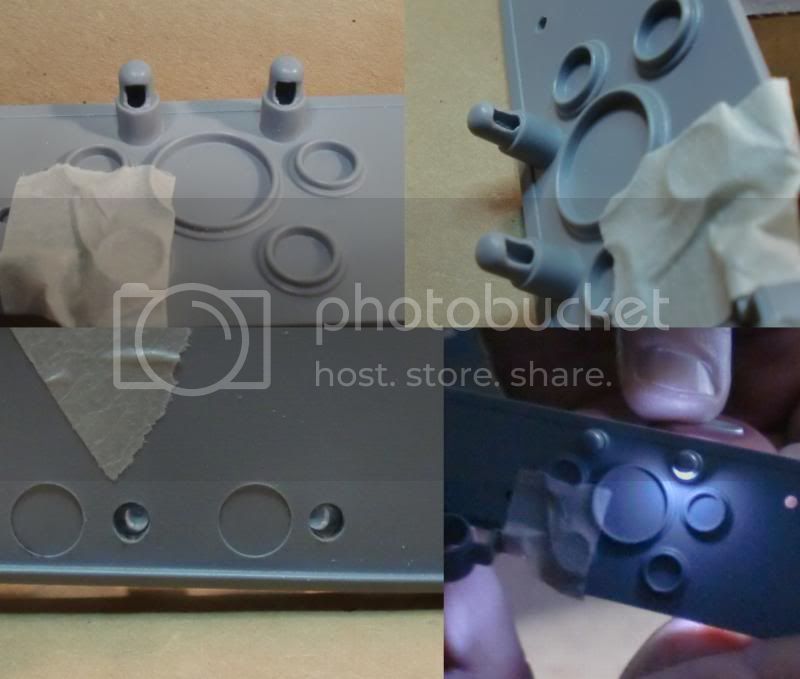
I was thinking that I might like to light the dash. I drilled out the dash lights from the bottom making sure not to drill all the way through. I then drilled in from the back until I reached the hole I just drilled from the bottom. Then I took my knife and carved the opening to the shape it is in now. The last image shows what it looks like with a LED light held up behind the opening. I havenít decided for sure to light the jeep up, but I do have the option to if I decide to do it.
I havenít felt like working on the engine, so I went ahead and created the brake master cylinder, the heat shield and the pluming for the brakes along the frame.
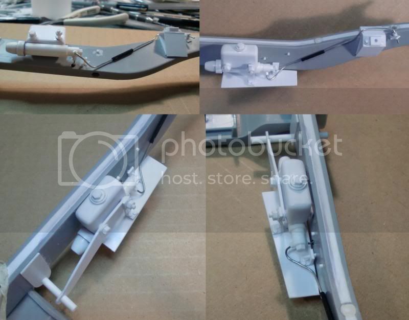
While I was building the master cylinder, I decided to build the steering box and the pedals too. Of course, the location of the steering column on the firewall didnít line up with anything except the fender, so I had to enlarge the opening several times until I got it in a position that would allow everything to line up. I now have a huge hole in the firewall to fill in and clean up. When I did the mockup to take pictures, I found out that I made the clutch and brake pedals too long. I have already shortened them and the glue is now drying.
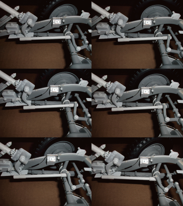
The steering output shaft interfered with the oil pump on the engine on my original design. I was able to rework the steering box and move the oil pump down a little on the engine block and now I have plenty of clearance. I think I re-did the steering box 3 times until I got it to where it is now. Then, when I put the axle on to find the length for the steering rod, I found out that the brake line ďTĒ connector was in the way of the steering rod. I got that moved too. Everything lines up and the steering is operational. The steering wheel doesnít move with the wheels, but everything else does. I am glad to have that finished up.
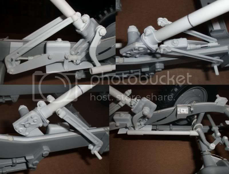
Sorry about the jumpy animation, but I was holding the camera in one hand, moving the wheels with the other, and the whole time trying to keep the exact same position of the camera and the chassis. I guess I need to get a small tripod for the camera.
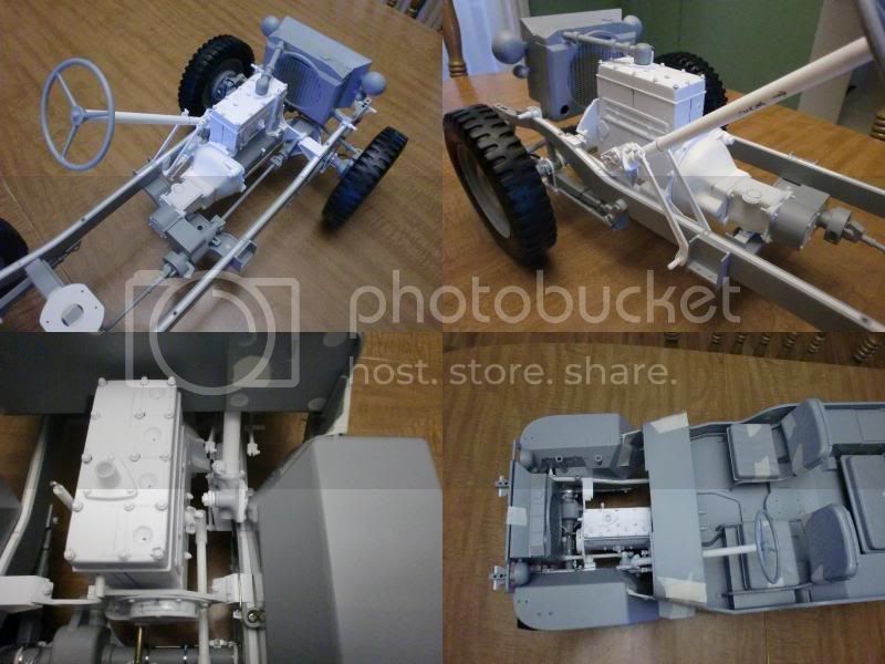
The last set of pictures shows a mock-up of the drive train as it stands now, both with and without the body.
Itís getting there, slowly but surely.
Thanks for looking.

I was thinking that I might like to light the dash. I drilled out the dash lights from the bottom making sure not to drill all the way through. I then drilled in from the back until I reached the hole I just drilled from the bottom. Then I took my knife and carved the opening to the shape it is in now. The last image shows what it looks like with a LED light held up behind the opening. I havenít decided for sure to light the jeep up, but I do have the option to if I decide to do it.

I havenít felt like working on the engine, so I went ahead and created the brake master cylinder, the heat shield and the pluming for the brakes along the frame.

While I was building the master cylinder, I decided to build the steering box and the pedals too. Of course, the location of the steering column on the firewall didnít line up with anything except the fender, so I had to enlarge the opening several times until I got it in a position that would allow everything to line up. I now have a huge hole in the firewall to fill in and clean up. When I did the mockup to take pictures, I found out that I made the clutch and brake pedals too long. I have already shortened them and the glue is now drying.
The steering output shaft interfered with the oil pump on the engine on my original design. I was able to rework the steering box and move the oil pump down a little on the engine block and now I have plenty of clearance. I think I re-did the steering box 3 times until I got it to where it is now. Then, when I put the axle on to find the length for the steering rod, I found out that the brake line ďTĒ connector was in the way of the steering rod. I got that moved too. Everything lines up and the steering is operational. The steering wheel doesnít move with the wheels, but everything else does. I am glad to have that finished up.


Sorry about the jumpy animation, but I was holding the camera in one hand, moving the wheels with the other, and the whole time trying to keep the exact same position of the camera and the chassis. I guess I need to get a small tripod for the camera.

The last set of pictures shows a mock-up of the drive train as it stands now, both with and without the body.

Itís getting there, slowly but surely.
Thanks for looking.
plane_mc

Joined: March 25, 2008
KitMaker: 91 posts
Armorama: 90 posts

Posted: Thursday, November 04, 2010 - 08:45 AM UTC
Just a real quick update today, I havenít really been working on my jeep for the past 3+ weeks. I was on vacation for a little over a week, and then I didnít really feel like working on it until last weekend.
I only got a little done, and someone is trying to convince me that I have lost my mind. I donít know that I can disagree with him.
Here are the clutch and break linkages operating. . .
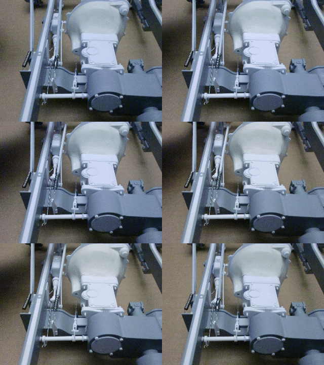
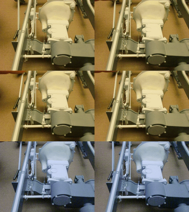
I was making the connections, figuring that I would be gluing it all together when I decided it wouldnít require that much more effort to make them operational. I know that it wonít be seen once the body is on, but I know it is there and works like the real thing.
Thanks for looking.
I only got a little done, and someone is trying to convince me that I have lost my mind. I donít know that I can disagree with him.
Here are the clutch and break linkages operating. . .


I was making the connections, figuring that I would be gluing it all together when I decided it wouldnít require that much more effort to make them operational. I know that it wonít be seen once the body is on, but I know it is there and works like the real thing.
Thanks for looking.

sgtreef

Joined: March 01, 2002
KitMaker: 6,043 posts
Armorama: 4,347 posts

Posted: Thursday, November 11, 2010 - 12:49 AM UTC
Damn Mark you are taking it to another level here.
Dang this is the best I have seen from a bunch of plastic parts in any scale.
Keep it up maybe a side line casting some of these items for sale.
Would make more want to build one with all the parts for sale.
You going to get the Panzer II B from Dragon?
Dang this is the best I have seen from a bunch of plastic parts in any scale.
Keep it up maybe a side line casting some of these items for sale.
Would make more want to build one with all the parts for sale.
You going to get the Panzer II B from Dragon?
Posted: Thursday, November 11, 2010 - 01:58 AM UTC
Bloody ell Mark that is outstanding,your work is awesome 
Andy

Andy
plane_mc

Joined: March 25, 2008
KitMaker: 91 posts
Armorama: 90 posts

Posted: Saturday, January 01, 2011 - 07:12 AM UTC
Itís been a while since I last updated, but I have slowly been working on this.
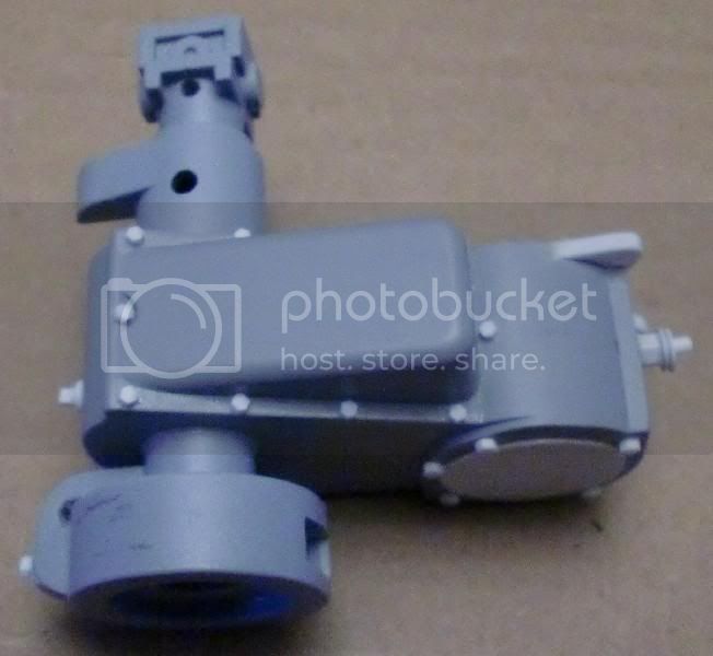
I added some details to the transfer case, mostly just bolt heads and a drain. I want to correct/detail the parking brake and add the shift levers and brackets eventually.
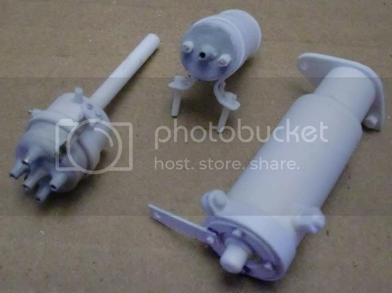
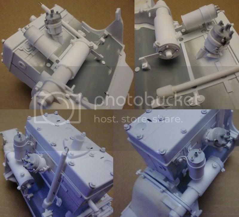
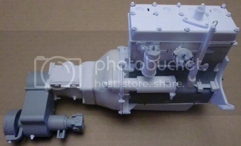
I made up the starter, distributor and coil, which pretty much finishes up the right side of the engine, except for the alternator.
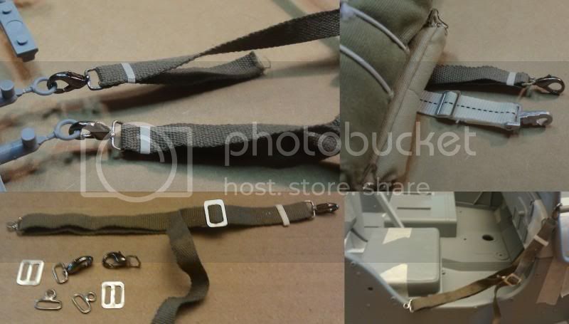
After finishing these parts, I was pretty much burned out on working on the engine/drivetrain. I needed a break from it. I decided to work on creating the door straps. I found some clasps at a local craft store that seemed to be the right size. I modified them by adding a wire rectangle for the webbing to go through. I then created the anchors from some more wire soldered up. The adjusters were made from some sheet aluminum.
I have been collaborating on some parts with .308. He helped me decide to get away from working on the drivetrain and start working on the .50 cal pedestal and mount. I would really like to thank Paul for all the help and for getting me motivated to get going again.
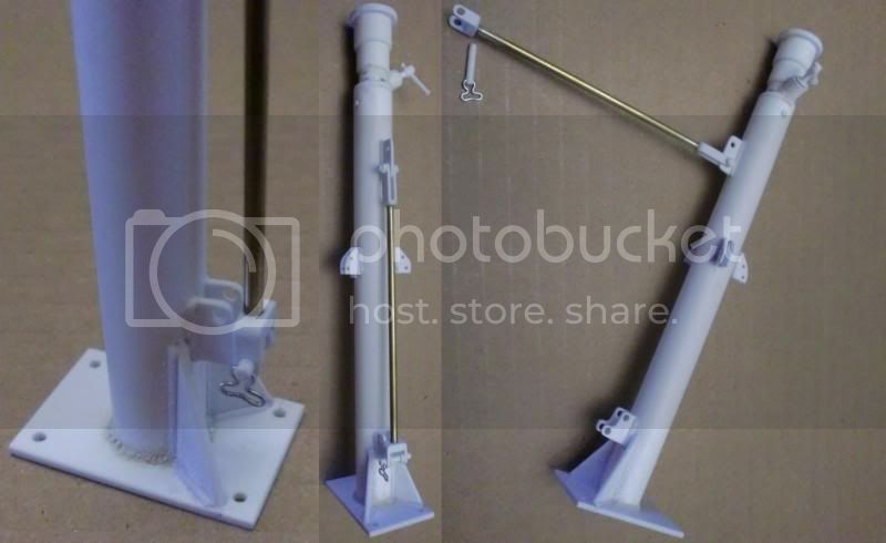
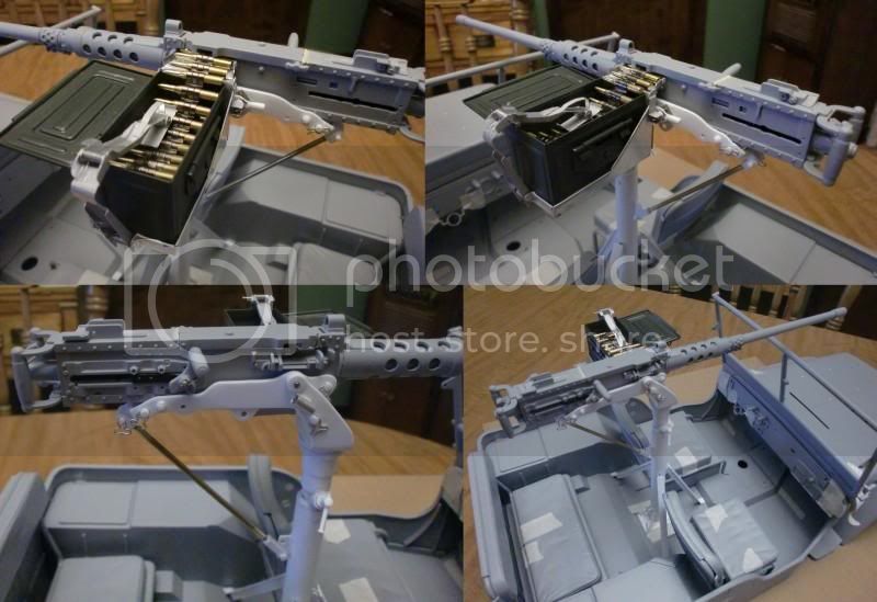
I had already built most of the pedestal, but needed to add the bracing and the support legs. I made all of these parts out of various sizes of sheet styrene. I then started working on the mount and cradle for the .50 cal. These were also made out of various pieces of sheet/rod/tubing styrene, with a couple of oddball metal pieces thrown in. It was mostly trial and error making these parts, I think I made each of them 3 times before I got the final pieces. The whole system is pinned so the .50 cal can be removed by removing the pins. I still need to go get some chain for it, but I am happy with the way it turned out.
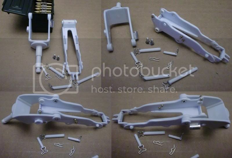
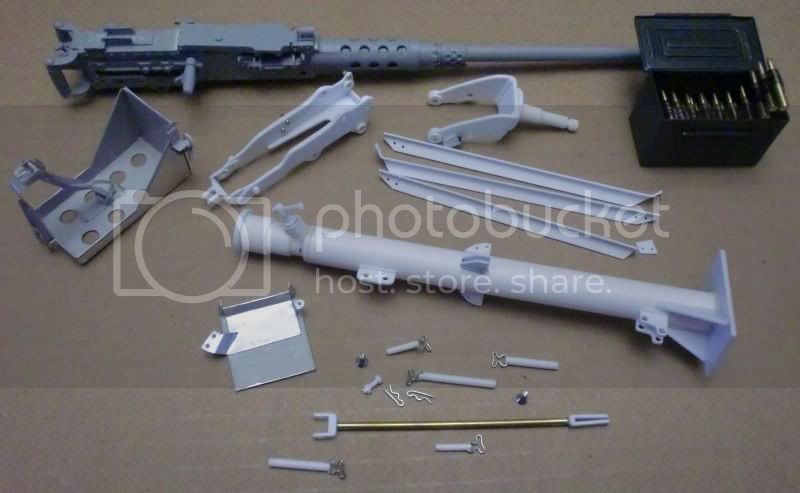
After getting the cradle and mount figured out, I started working on the ammo holder. This is where .308 really helped me out. I previous conversations with him, I learned about the aluminum sheet he uses to make some of his parts. This turned out to be the perfect material to use for the ammo holder. I had found a picture of a photoetch holder for 1/35 scale. .308 was able to clean up the picture for me and get me a good line drawing to start with. I then modified the drawings to make the final piece shown here. I started by making the holder out of cardstock so I could easily make changes and just print out the new pieces.
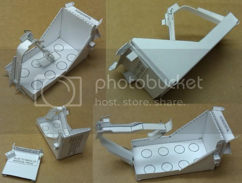
After I was happy with the parts in cardstock, I transferred the design to the aluminum sheet. I then carefully cut it out and folded it up and glued where necessary to get the pieces shown below.
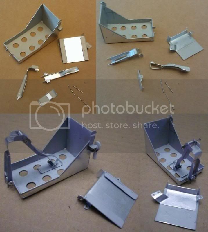
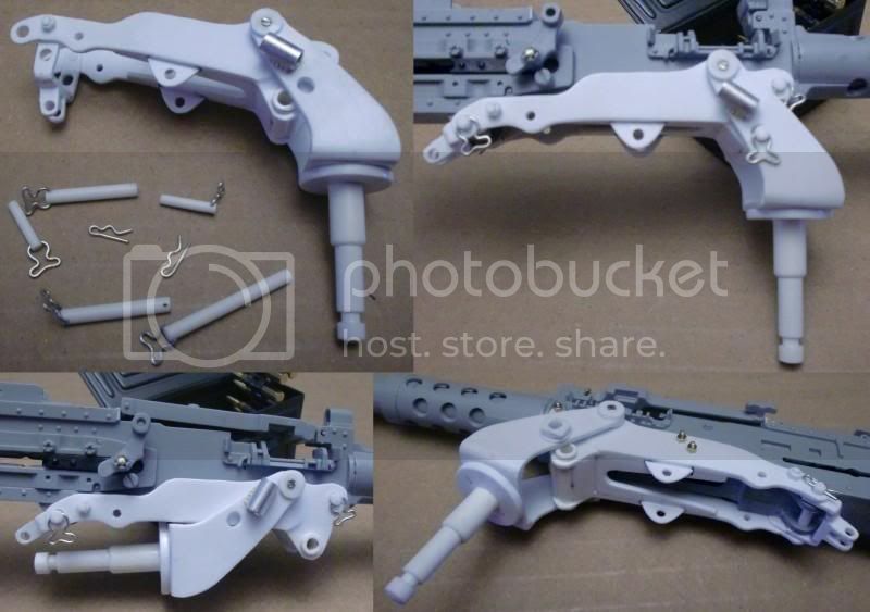
I then mounted the ammo holder to the cradle using 00-90 screws and nuts. Here is the almost finished assembly.
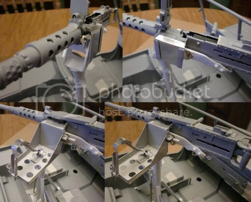
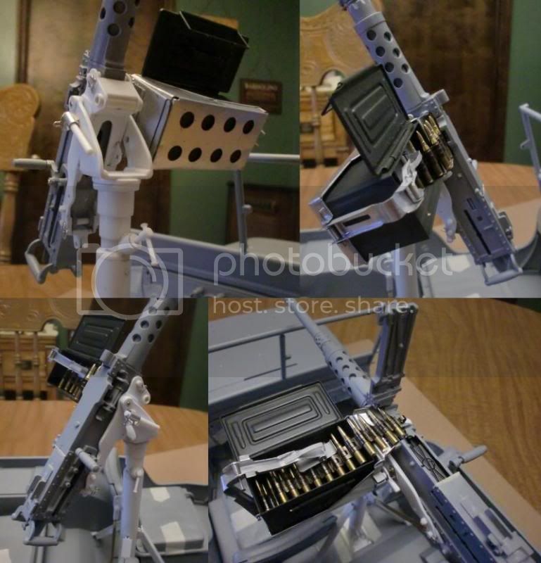
Here are all the pieces that make up the gun system.
I had spend a lot of time trying to figure out how I was going to make this piece and .308 really made it easy for me. Thank you so much.
Thatís all for now, thanks for looking.
I added some details to the transfer case, mostly just bolt heads and a drain. I want to correct/detail the parking brake and add the shift levers and brackets eventually.

I made up the starter, distributor and coil, which pretty much finishes up the right side of the engine, except for the alternator.


After finishing these parts, I was pretty much burned out on working on the engine/drivetrain. I needed a break from it. I decided to work on creating the door straps. I found some clasps at a local craft store that seemed to be the right size. I modified them by adding a wire rectangle for the webbing to go through. I then created the anchors from some more wire soldered up. The adjusters were made from some sheet aluminum.

I have been collaborating on some parts with .308. He helped me decide to get away from working on the drivetrain and start working on the .50 cal pedestal and mount. I would really like to thank Paul for all the help and for getting me motivated to get going again.
I had already built most of the pedestal, but needed to add the bracing and the support legs. I made all of these parts out of various sizes of sheet styrene. I then started working on the mount and cradle for the .50 cal. These were also made out of various pieces of sheet/rod/tubing styrene, with a couple of oddball metal pieces thrown in. It was mostly trial and error making these parts, I think I made each of them 3 times before I got the final pieces. The whole system is pinned so the .50 cal can be removed by removing the pins. I still need to go get some chain for it, but I am happy with the way it turned out.


After getting the cradle and mount figured out, I started working on the ammo holder. This is where .308 really helped me out. I previous conversations with him, I learned about the aluminum sheet he uses to make some of his parts. This turned out to be the perfect material to use for the ammo holder. I had found a picture of a photoetch holder for 1/35 scale. .308 was able to clean up the picture for me and get me a good line drawing to start with. I then modified the drawings to make the final piece shown here. I started by making the holder out of cardstock so I could easily make changes and just print out the new pieces.

After I was happy with the parts in cardstock, I transferred the design to the aluminum sheet. I then carefully cut it out and folded it up and glued where necessary to get the pieces shown below.

I then mounted the ammo holder to the cradle using 00-90 screws and nuts. Here is the almost finished assembly.


Here are all the pieces that make up the gun system.

I had spend a lot of time trying to figure out how I was going to make this piece and .308 really made it easy for me. Thank you so much.
Thatís all for now, thanks for looking.
casailor
Joined: June 22, 2007
KitMaker: 165 posts
Armorama: 97 posts
KitMaker: 165 posts
Armorama: 97 posts

Posted: Saturday, January 01, 2011 - 11:03 AM UTC
Amazing work. Not to be nitpicky, but you might do a little research, I am 99% certain that only reusable fabric belts were used on ma duces in WWII. Given the great work you did on the D R straps, fabric ammo belts wouldn't be too much of a challange for you. I wish I hade your abilities.

Rattler

Joined: November 23, 2002
KitMaker: 512 posts
Armorama: 277 posts

Posted: Saturday, January 01, 2011 - 11:40 AM UTC
Simply stunning work !!!!!!!!!!!!!.... hell I should contract you to do the 50 cal stuff I need done lol beauitful man just WOW
Richard," Not to be nitpicky, but you might do a little research, I am 99% certain that only reusable fabric belts were used on ma duces in WWII."
I'm curious are you referring to the ammo belt ?
Richard," Not to be nitpicky, but you might do a little research, I am 99% certain that only reusable fabric belts were used on ma duces in WWII."
I'm curious are you referring to the ammo belt ?
plane_mc

Joined: March 25, 2008
KitMaker: 91 posts
Armorama: 90 posts

Posted: Sunday, January 02, 2011 - 12:09 AM UTC
Quoted Text
Amazing work. Not to be nitpicky, but you might do a little research, I am 99% certain that only reusable fabric belts were used on ma duces in WWII. Given the great work you did on the D R straps, fabric ammo belts wouldn't be too much of a challange for you. I wish I hade your abilities.
Thank you for the comments Richard. From the research I have done, it appears that both the belted and linked ammunition was used during WWII. I have seen pictures of both types being used during the war. I appreciate you bringing it to my attention though, I am trying to be as accurate as I can be with this build.

BLACKWATER

Joined: August 05, 2010
KitMaker: 449 posts
Armorama: 441 posts

Posted: Sunday, January 02, 2011 - 12:33 AM UTC
Perfect details, you are an artist.
Cheers
Blackwater

Cheers
Blackwater


Posted: Sunday, January 02, 2011 - 01:34 AM UTC
Hi Mark. Ive never been interested in bigger scales, but seeing the level of detail and how good it looks, I must say its tempting. The problem is, I definately donīt have your scratchbuilding skills. What youīve done so far is amazing! 

plane_mc

Joined: March 25, 2008
KitMaker: 91 posts
Armorama: 90 posts

Posted: Sunday, January 02, 2011 - 03:15 AM UTC
Thanks for the kind words everyone. I would just like to state that I do not have any special skills. I also thought that I could never scratch build anything, but after looking at the pieces, I just broke them down into simple shapes. Maybe a rectangle, square, tube, etc. After doing that, you just start adding the other details one at a time and before you know it, you have a completed piece. Look at the engine, in the beginning, it was just a rectangle for the block. After that, I slowly added strip/rod/hex/etc details to it until it is where it is now. Trust me when I say it . . . If I can do it, anyone can.
I would also like to state that I am only using basic hand tools for all my scratch building. The only power tools I use are a dremel and a cordless drill for the larger holes.
Frank, you should give the large scale a try. Adding the extra details is not that hard and the finished piece looks impressive.
jeepman

Joined: May 25, 2003
KitMaker: 22 posts
Armorama: 22 posts

Posted: Sunday, January 02, 2011 - 06:32 AM UTC
Mark,first let me say Fantastic work!!!! Just some info for you ,your oil dipstick tube ahead of the distributor has the wrong top.Yours is from the prewar MA model with straight sides.The MB/GPW tubes have a tapered flare at the top with a large diameter push on cap on early versions and a twist on cap with two tabs sticking up on the cap for grip on most WW2 production.Volume two of All-American Wonder by Ray Cowdery shows this on page 227.Volume 1 and 2 of these books are considered essential items by WW2 jeep restorers.I am presently restoring a 1943 MB.Wish I was tech savy enough to post you a picture.Like I said Fantastic.
plane_mc

Joined: March 25, 2008
KitMaker: 91 posts
Armorama: 90 posts

Posted: Sunday, January 02, 2011 - 07:26 AM UTC
Thank you Jeepman, I will have to look into some more and update it as necessary, I appreciate the feedback. It matches the photo I was looking at at the time. I am just going by photos that I find as I go along. I am definitely not an expert on the jeep, I am learning as I go.
I am envious of you restoring a real one, I would love to get a hold of one to work on.
I am envious of you restoring a real one, I would love to get a hold of one to work on.
jeepman

Joined: May 25, 2003
KitMaker: 22 posts
Armorama: 22 posts

Posted: Sunday, January 02, 2011 - 10:42 AM UTC
Mark,if you want a site with many color pictures of WW2 jeep parts try www.1943mb.com It has a bunch of how to repair articles with pictures on Jeep repair.The oil dipstick tube can be found in the oil change section under engine repairs.By the way restoring a real one is lots more expensive than modeling one. 

 |


