Right, the second instalment!
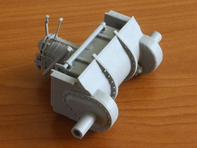
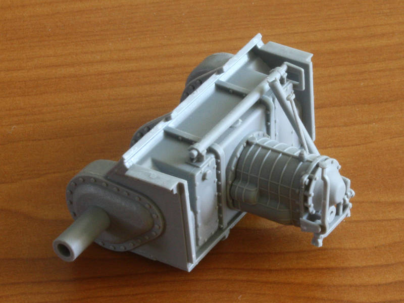
The review went off, and I can now reveal the three main areas of concern that prompted this blog were the tranny, the gun mount, and the upper hull assembly. Weve looked at the tranny, so on to the gun mount!
The first thing to point out is that the instructions are rather vague about parts location and assembly stages. They also show the parts built up in a sequence that would certainly lead to damage later on I found it best to throw the sequence away and start from first principles.
The second thing to point out is the frailty of many of the parts as well as the lack of positive locators on many of them.
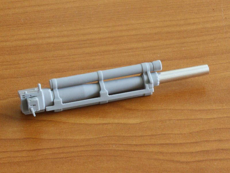
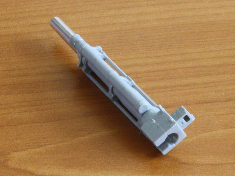
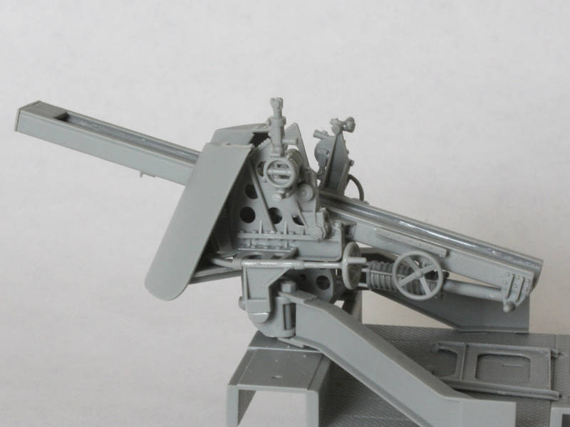
I decided it was best to start by gluing up the gun assembly (step 5), but got seduced by the detailed breech block. I posed it open, but forgot that the operating handle is moulded into the breech in the closed position. So, Ill be carving and making a new one from plastic strip
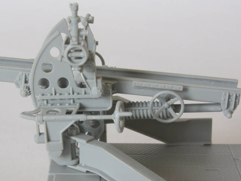
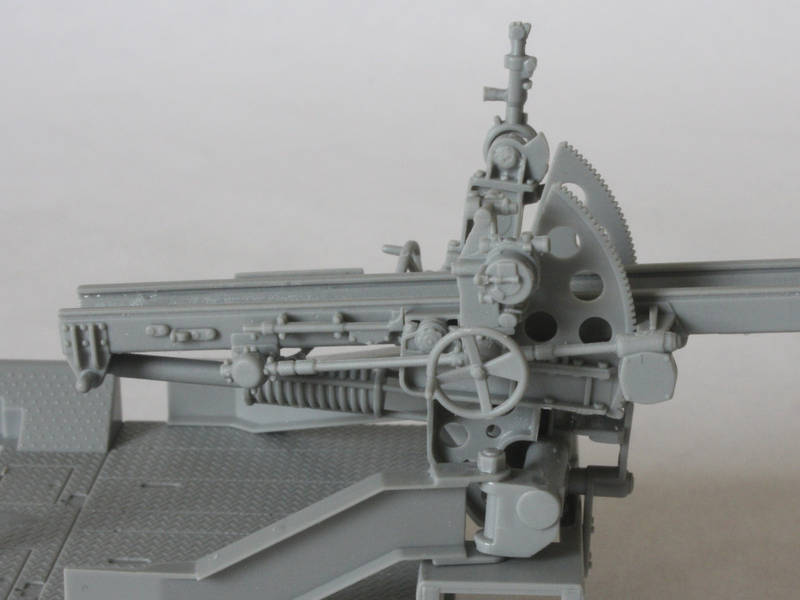
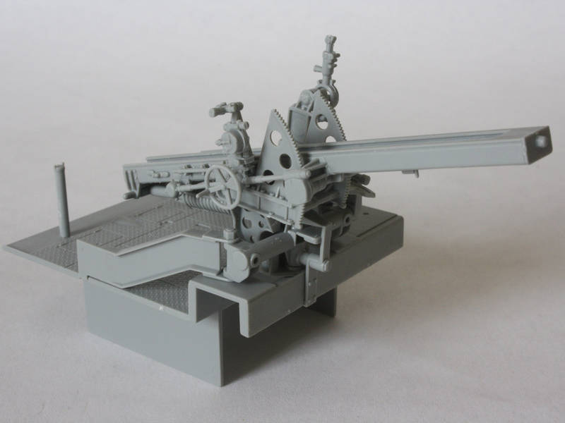
Next up I glued the gun cradle sides together, being careful to preserve the two pins at the rear (for the travel lock) even though the instructions say to cut them off. True, they arent really well detailed, but are better than nothing! The instructions would have had me add side details onto each cradle half before they were joined, but that would have ensured breakages as I held the two sides together and would have affected my ability to deal with the seam down the middle. In fact, I left these off until after adding the two sides of the elevation gear in which the cradle sits.
I wanted the gun to elevate, so I did not glue the cradle pivots where they are trapped by the elevation gear. (The instructions dont suggest this
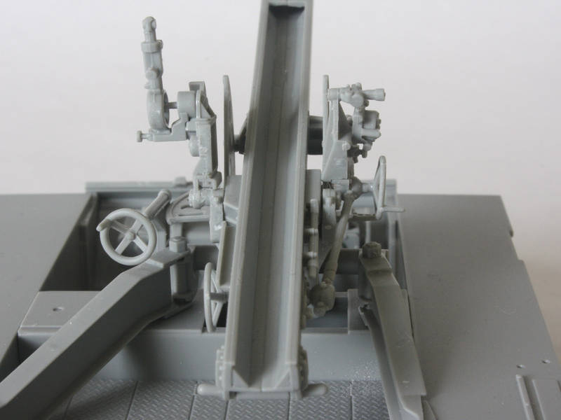
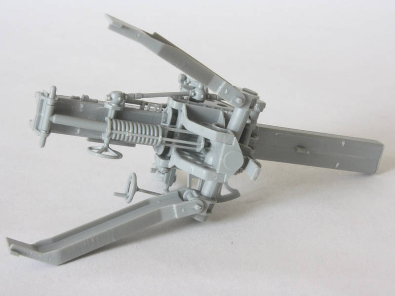
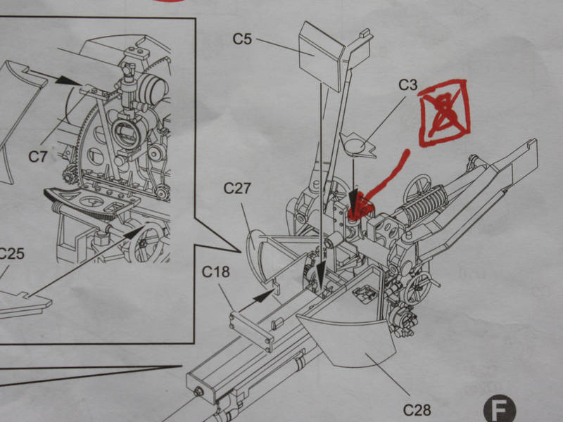
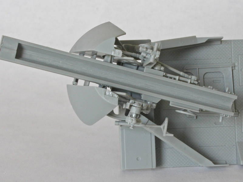
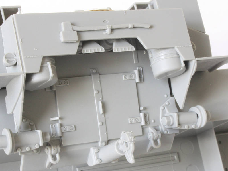
) Once the elevation gear halves were secure I then set about building the mount with its trails because I wanted to get all the architecture done before adding any fragile detail. I glued the yoke to the two trails and set the assembly on the fighting compartment floor to dry overnight. Later I took it off the floor and trapped it under the elevation gear with the bottom plate C3 I was careful not to glue the yoke, so it can pivot side to side.
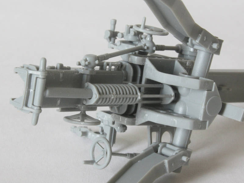
Underneath the cradle there is a cylinder that attaches the cradle to the elevation gear. The front mount under the elevation gear is an impossibly tiny part that locates into a hole in the front face of the gear, and the cylinder snaps in between the two sides of this mount with incredibly tiny pins. I left the piston loose in the cylinder and snapped its T-shaped end between the lugs at the rear of the cradle. If you glue this assembly it would lock up the cradle preventing it from elevating.
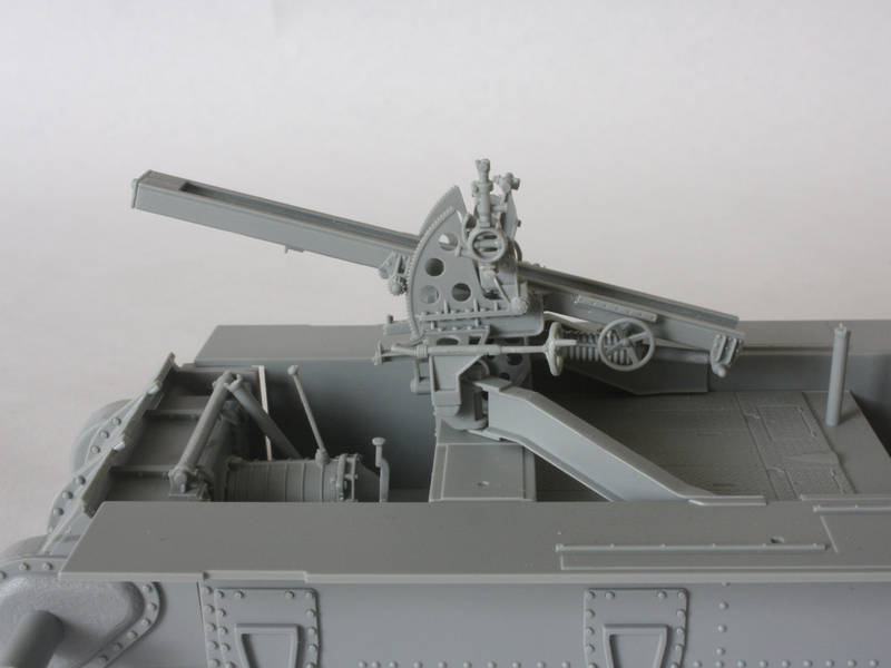
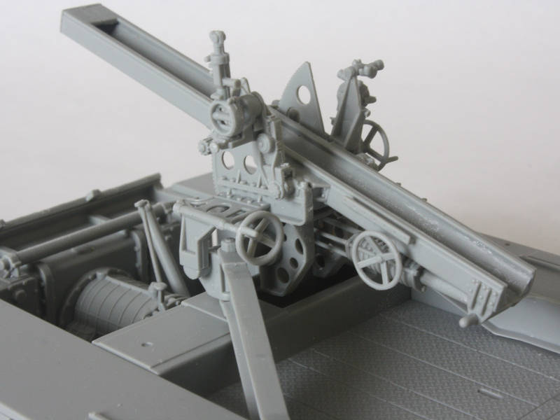
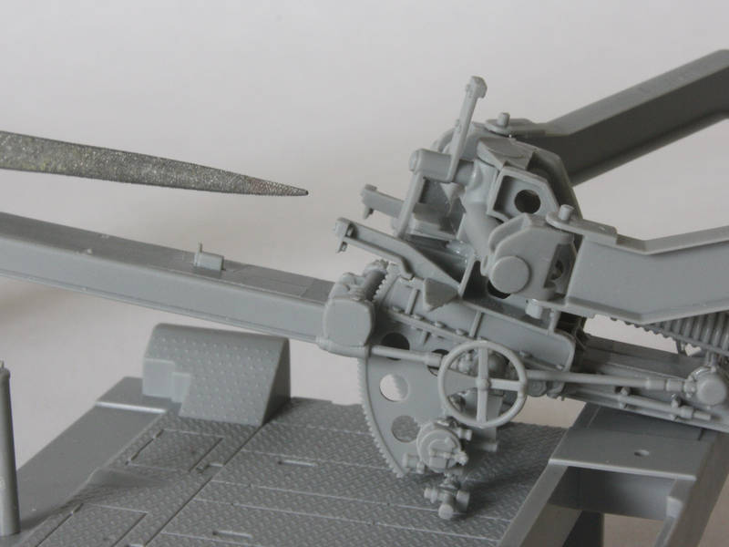
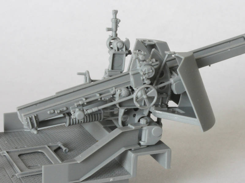
After all the structure was done I turned to the details that Id skipped. Most are fairly straight-forward, but the sights on either side are nightmares! I found the parts to be a very vague fit, and the illustrations were unhelpful. I think I made a decent job in the end, and offer my photos as a guide to proper assembly. On the left side the sight sits on the elevation gear, but fouls the cradle, so I added a small spacer to shift it over enough to be out of the way. (I cut a thin slice from one of the many ejector nubs that I cut off the parts
) Oh, and I left the handwheels off til last.
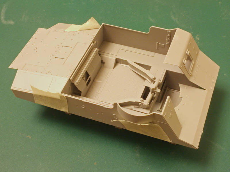
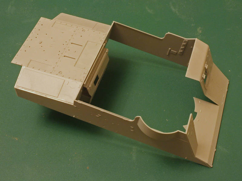
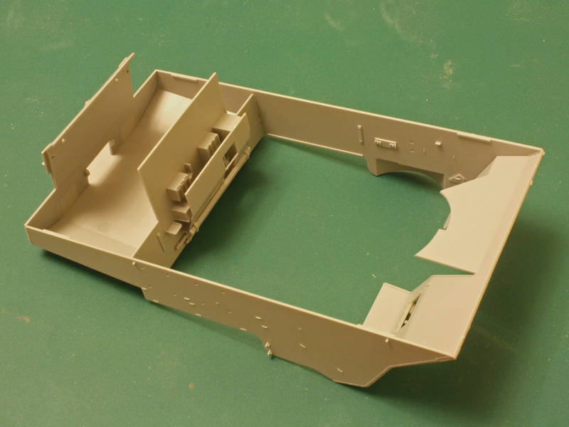
When I finished adding details I noticed that the yoke is effectively clipped in place on the floor by part C1, so I think I may glue it to the floor, and paint the floor as a separate assembly from the lower hull. If I do, then the whole floor assembly can be left loose until the upper body is fitted to the hull so I can wiggle it all into place.
The gun sits in the cradle and is supposed to be glued, but Ill leave it off until after painting. Pity it doesnt snap-fit
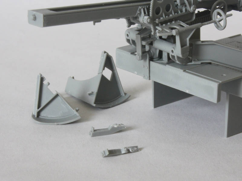
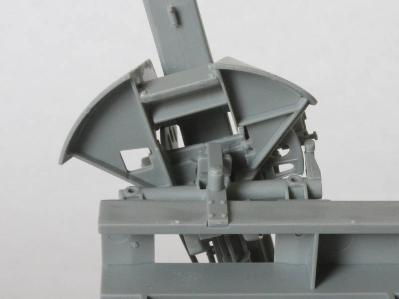
The only thing left is the shield. I built up the two halves, but struggled with location, so I put it aside for the night! I then saw Tony (callsign PvtMutt) posting his M7 build in the Shermans campaign, and he was kind enough to PM me with the solution. It seems that parts A29 and A30, which fit under the elevation gear halves, are left-overs from the earlier kit of the towed 105mm field piece, and are effectively replaced on the M7 by the floors of the gun shields C25 & C26.
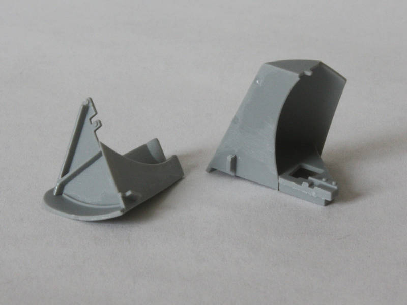
These fit up from underneath, and are then held together with part C18. Of course by this point I had already fitted A29 & A30, so I now had to carefully pry them off! Much swearing and replacement of dislodged details followed. So, lesson for the day? Dont attach parts A29 & A30!
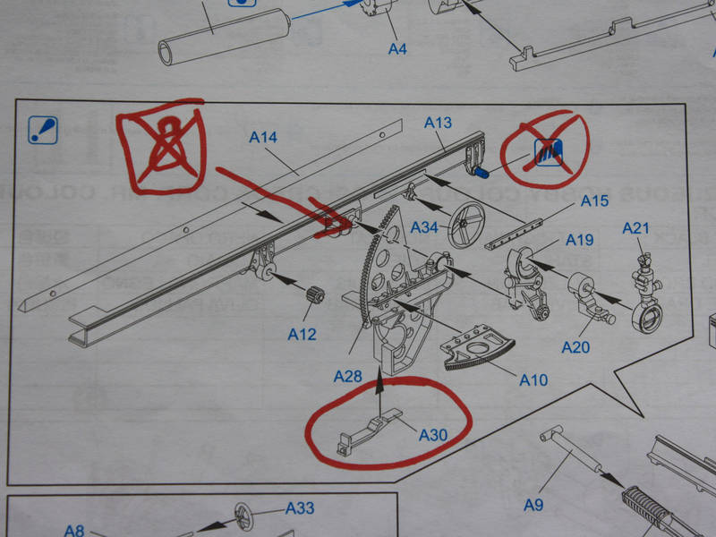
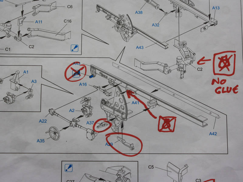
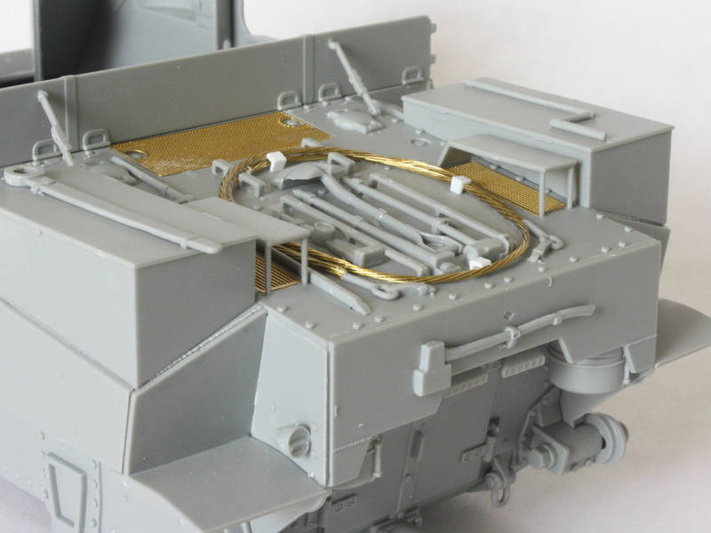
To round off, here are the kit instructions, duly marked up to show parts that shouldnt be glued, as well as the offending parts (circled) and the nubs that must be retained.
Next time: the upper hull!
Tom


