_GOTOBOTTOM
Armor/AFV: Axis - WWII
Armor and ground forces of the Axis forces during World War II.
Hosted by Darren Baker
Pz.Kpfw. IV Ausf. F2 (G) (Workhorse Campaign)
Braille
#135
Visit this Community
California, United States
Joined: August 05, 2007
KitMaker: 1,501 posts
Armorama: 1,485 posts
Posted: Friday, September 10, 2010 - 06:40 PM UTC
Armorama Track-Heads, Septem-BEER is here! (Root beer for the younger crowed)

I will be putting together Dragon's 1/35th scale Pz.Kpfw.IV Ausf.F2 (G) kit #6360 for the Workhorse Campaign. I originally had another kit in mind to build for the campaign but my wife surprised me with this kit on my birthday. And after reading through Ken Schwartz's 1/35th scale Pz.Kpfw IV Ausf.F2(G) in box review. I just new I would have fun putting this kit together. And then I seen Fahri Mamedov's awesome Pz.Kpfw. IV Ausf. F2 in the Features section built straight OOTB! I also remember following Bill Plunk's excellent and informative Pz.Kpfw. IV Ausf. F2 Africa build log and wanting to run out to the LHS to purchase this kit and try out some sort of tropical scheme that Bill had featured as part of his build.
Thanks to the Workhorse Campaign (for the motivation) and my wife's thoughtfulness I'm getting the chance to build this kit and finally try out a tropical paint scheme. I don't know that I will be able to complete this build on time even with the extra allotted time frame of the campaign - due mostly to me being such a slow builder - so I've chosen to post and share my progress here with you just in case the campaign ends and I still haven't finished with this build. And because of the step by step build process that I have in mind I don't want to hog up a lot of pages with my postings in the campaign. Being my first build log I'm treading on new territory so please bear (or beer) with me. Hopefully we can all learn a little from each other and have some fun in the process.

Here are three photos and a color plate that I pulled off the internet of the vehicle that I have chosen to model . . .


. . . its of the exact tank that's rendered on the kit box cover art by Ron Volstad (nice touch with the entire village ablaze in the background) and one of the seven painting and marking options available in the kit. I couldn't find any photos of the front of this vehicle? I don't know exactly where in Russia these photographs were taken but I had read that they were taken in 1942 somewhere in southern Russia?


Nice detailed single sided color plate - gives a good idea of the colors used and how the overall vehicle was painted.
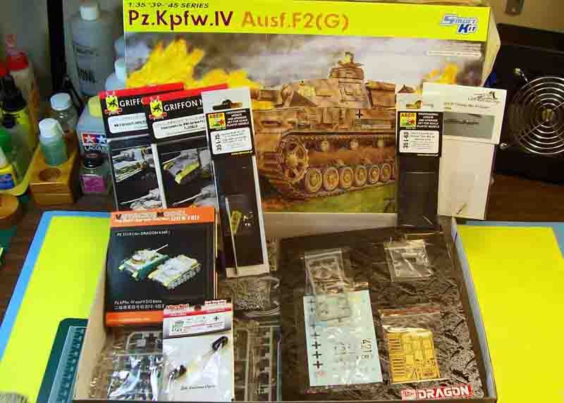

The kit and most of the aftermarket items that I will be using. Still waiting on the Modelkasten workable track links.

List of the aftermarket items:
Aber #35 L-75 German KwK.40 L/43 7.5cm metal barrel with brass single baffle muzzle brake.
Aber #35 L-63 German tank 7.92mm MG 34 (Late) brass machine gun set (will be using only one of the two barrels in the set for the turrets coaxial station).
Adlers Nest #AMN 35008 Brass 2m Antenna.
Griffon Model #L35018 German Pz.Kpfw.IV Ausf.F2(G) / Ausf.G (2 in 1) full detail photo-etch set for Dragon 6360 / 6363.
Griffon Model #L35A010 German track fenders for Pz.Kpfw.IV Ausf.F1 / F2(G) / Ausf. G accessory photo-etch set for Dragon 6315 / 6360 / 6363.
Lion Mark #LM10029 German tank 7.92mm MG 34 (Late) brass machine gun (for the R.O.'s station).
ModelKasten #MK SK-18 40cm opened horned workable track link set.
Tristar #35014 German Pz.IV Wheel Set.
VoyagerModel #PE 35141 German Pz.Kpfw.IV Ausf.F2(G) basic photo-etch set (IMHO this set compliments any of the full detail photo-etch sets currently on the market for this kit).

"But it's a Smart Kit!" I kept telling that super glue sniffing junky, plastic little devil on my shoulder. But he kept tempting me on . . . "I know, I know, but you shouldn't just build it straight Out Of The Box!" My wife still doesn't believe my story but I'm sticking to it!

Well, here goes with this step by step, PIMP my Panzer IV, build log.

The first step I take before beginning any assembly work is not shown. This is where I use my wife's large glass baking pan filled with warm water and a little bit of dish washing soap to bath all of the parts while they are still on the sprues for about 10 minutes and lightly scrub them with a soft toothbrush to remove any mold release that may still be on the plastic. I then rinse the sprues off in cold running water . This step is very important as acrylic paints won't adhere very well or not at all to the plastic due to the mold release. I also use my wife's large colander to keep any parts that may have come off of the sprues during the washing and scrubbing process from escaping down the drain. I sometimes use her blow dryer to dry up the parts that I want to start on right after the washing but mostly I allow the parts to air dry by themselves. The other important step is dry fitting of the parts before committing them to the liquid or gooey cement monsters. I almost always build my kits from the inside out and rarely if ever follow the kits sequenced assembly instructions. I do however check out every section on the instructions and look at every part before I begin a build. So with that said I will be skipping around quite a bit during the build.


Per step 1 of the instructions I installed both forward side pieces that contain part of the final drive / differential housing flange (E8 - Right Side and E9 - Left Side) to the lower hull (Y). Followed by the [50mm / 14 deg.] bow armor plate with the [30mm / 61 deg.] lower bow armor plate (E16). And from step 5 the [20mm / 72 deg.] front glacis armor plate (E30) together with the support / alignment bar for the upper hull (E18). Except for the final drive / differential flange I filled the seams along the forward sides of the lower hull with super glue. I dampen the end of a micro brush with accelerator then place the dampened micro-brush on the plastic near the edge of the super glue. The accelerator is drawn to the super glue and within a minute your ready to start sanding. I usually slice away as much super glue while its still soft with a new X-Acto blade until almost reaching the surface of the plastic before I start sanding. The super glue is quite pliable when it first sets up and sands down very much like plastic. But the longer you wait the harder the super glue becomes getting rock hard within a couple of hours making removal difficult. Unlike many of the available filler putty's for plastic models super glue won't shrink after it completely cures. What appears to be seams on the surface where the parts are joined together in the photo is actually the transparent nature of the super glue when wet sanded to a smooth finish. By placing super glue on wax paper it won't set up and will last you through one session of modeling. I use a sewing needle or a #11 X-Acto blade as an applicator. After achieving a desirable finish on both sides I installed only the final drive / differential housing (A14) from the sub-assembly section of step 3 to both sides of the forward lower hull.


Step 5 provides you the option of installing the seven piece track links over the center of the transmission access hatch seen on some later Ausf. F2's and most early G's. I decided to forgo this option and leave the glacis armor plate without the track links so I went ahead and removed all of the lightly raised molded on placement detail for the track link support brackets. And while I was removing this I also removed the right fender stay hardware post and a few other details that will be replaced with photo-etched items. I also added the dowel pin holes on the brake access hatch hinges (this process in described below on the fuel filler hatch hinges).


This view shows the three rear pieces in step 1 of the instructions that mate up with the lower hull (Y) to produce the lower rear armor plate sections of the tank. I first removed the molded on fender, main engine and turret power traverse motor muffler support bracket that spans the upper edge of the upper vertical armor plate (E13). I had to replicate a couple of items that are molded on the bracket that were lost during removal that I will be showing you later in the build. The removed bracket will be replaced with a photo-etched replacement. A few of the rivets nearest the bracket were damaged during the removal but I was able to renew them with a little bit of super glue applied with a sewing needle. The lower vertical armor plate (E26) was then cemented together with the upper vertical armor plate almost completing the sub-assembly section of step 1 minus the engine starter crank handle port cover (E29). These two pieces make up the 20mm / 10 deg. lower hull rear vertical armor plate on the real tank. I next cemented the [14.5mm / 74 deg.] bottom angled armor plate (E11) to the bottom of the lower hull. The two upper vertical armor sub-assembled sections were then cemented to the hull rear and bottom angled armor plate.

The towing hold is not installed until step 4 where you have the choice of selecting one of three towing holds. I selected the plane towing hold (H45) without any of the hardware for the towing pintle because this is the correct piece for the vehicle I am modeling. Of the two other towing hold options one comes with hardware (H49) for attachment of the towing pintle support brackets and the other towing hold (H23) comes already fastened with the towing pintle support brackets for the towing pintle. The towing pintal itself is made up of two parts (H13 and H26). Although I won't be using these parts on my build I thought that I'd mention them to you as many of the later production F2's and almost all of the early production G's had the towing hold upgraded for using the towing pintle. I thinned down the towing hold from underneath to maintain its original height and along both sides of its two vertical support braces for a better scale thickness and to match the surrounding brackets on the vertical armor plates. I then installed the towing hold to the lower vertical armor plate with its two vertical support braces resting on the bottom angled armor plate.

Some of the location holes for mounting both the main engine and turret power traverse motor mufflers were filled with plastic rod in preparation of replacement photo-etched muffler support bracing. I used a micro-drill chucked in a pin vise to drill a hole on the lower left corner of the upper vertical armor plate for the electrical cable (not yet installed) that leads to the left rear fender mounted vehicle distance indication light and added a Verlinden Productions resin bolt head on the opposite corner (cable and bolt shown on one of my photo reference books). From step 3 are both the rear towing hooks (H57 - Left Side and H58 - Right Side) installed to their respective mount bases on opposite ends of the upper vertical armor plate (the towing hooks and mount bases are actually a single casting). And from step 4 the cold weather heat exchange water pipe (H25) near the lower center of the upper vertical armor plate. Of note; the water pipe coming out of the upper vertical armor plate is fixed parallel to the horizontal plane and not parallel with the angle of the bracket that sits just below the pipe. And also from step 4 both idler wheel mount assemblies have been installed on the right and left sides of the lower vertical armor plate.


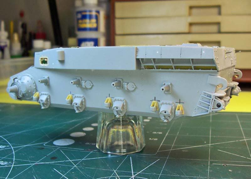
The 10 suspension arm dampers (A13) with the suspension arm damper support brackets (W5) from the Tristar Panzer IV Wheel Set and 8 bogie wheel suspension mounts (A38 - Left Side and A39 - Right Side) from step 3 have all been installed on both sides of the lower hull. The molded on fender support brackets that span almost the full length along the outside top edge of the left and right side [30mm / 0 deg.] vertical armor plates on the lower hull have been carefully removed. Both of these fender support brackets will be replaced with photo-etched items. Not mentioned on the assembly instructions is to have you remove the 6 large molded on tabs (3 per side) that sit along the top edge of the right and left side vertical armor plates on the lower hull. You won't be able to fit the kits fenders into place without first removing these tabs.


I chucked both a sewing needle and a micro-drill into a pair of pin vises to replicate the dowel holes on the fuel filler hatch hinge bosses. The sewing needle was used to indent the plastic to help keep the micro-drill stay centered on the hinge bosses. Both appearance sides of the hinges received this treatment.


Here on the right side idler mount assembly I've sandwiched a small styrene disk between the idler shaft adjusting nuts (A25) and the two piece idler mount housing (E23 / E33 - Right Side) to produce a similar gap that I had taken note of on my photo reference book. I also added a styrene disk to the left side idler mount assembly.


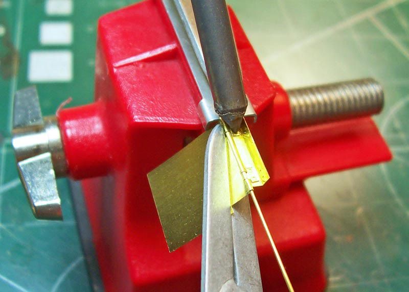
By now you've probably already noticed the brass thingamajig on the towing hook so I'll explain that first. The towing hooks come molded with a small boss for the triangular shaped cable stops just like on the real ones but you'll have to fabricate your own cable stops as no one makes these pieces that I am aware? Nice touch if you happen to leave off one or both of the rear mudflaps or store them in the up position. I left just enough tension on the brass cable stops after forming them with pliers to grab the towing hook boss and applied a tiny amount of super glue with a sewing needle to set them in place. There are a couple of rectangular plates (E32 - Left Side and E31 - Right Side) from step 4 that need to be fitted against the idler mounting braces located on the rear of the lower hull. These rectangular plates together with the 5 triangular shaped mounting braces molded to the bolted on base plate, on each side of the rear lower hull, were welded together forming the idler mounting bracket on the real tank. Once the rectangular plate was set in place and the seams filled I then cemented the 3 piece idler mount (E24 / E34 - Left Side with A25) sub-assembly from step 4 into place. I repeated the same process for the right side idler mount assembly. I left off the adjusting tension handles for later. The horizontal bracket on the lower end of the the upper vertical rear armor plate extended past the idler mounting bracket on both the right and left sides on my kit. I sanded the horizontal bracket down even with the idler mounting bracket as shown on my photo reference books. I also noticed that the horizontal bracket was a bit over scale on the ends so I went ahead and thinned down both ends of the horizontal bracket to match the thickness of the plates on the mounting bracket.


Side view of the left side horizontal bracket thinned to match the plates on the mounting bracket.


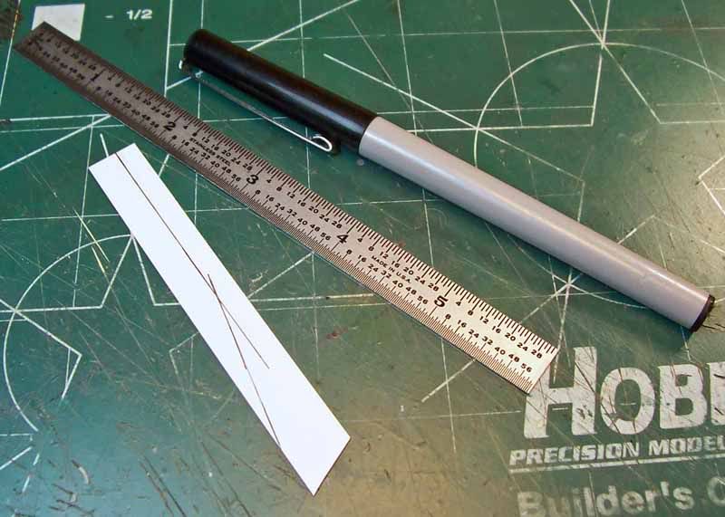
A comparison shot of the kits suspension arm damper support bracket on the left and Tristar's offering on the right. Now which ones should I go with? Hummm. . . I removed the locating pins on the backside of the suspension arm damper support brackets because they did not match up with the locating holes the hull. I marked the hull with a permanent ink marker using a small 6" scale metal ruler to help me with locating the suspension arm damper support brackets. I then test fitted one of the kit suspension arm dumper to the Tristar suspension arm dumper support bracket and found that the locating pin on the kit suspension arm damper matched up with the locating hole on the Tristar part. The locating pin on the suspension arm dumper was a little long so I trimmed it flush to the Tristar part. After assembling all 10 suspension arm dumpers to the suspension arm dumper support brackets I cemented the completed sub-assemblies from step 3 to the lower hull.


Here you can see that the Tristar bogie wheel suspension mount housing is a tiny bit larger than the kit part. I decided to go with the kits bogie wheel suspension mount housings.


Although I won't be using the Tristar bogie wheel suspension mount caps I thought I'd share them here with you. They won't fit onto the kits bogie wheel mounts - you can see that they're just a bit larger in diameter that the kit pieces.

I may or may not be using some of the Tristar working suspension components as the kit comes supplied with a non working bogie wheel suspension and I wanted to have the option of a working suspension? Anyhow, here's what I had to do to adopt some of the Tristar working suspension parts to the Dragon kit in the event I do decide to use the working suspension?


I assembled 8 of the Tristar 3 piece quarter elliptic leaf spring suspension arms (s1-14 / s1-15 - Left Side with s1-11 and s1-22 / 1s-23 - Right Side with s1-11). I had thought to use the kits suspension arm end piece (A48) but the Tristar's hollowed out end piece(s1-11) matched my photo reference book. The end piece is actually a part of the casting on the quarter elliptic leaf spring suspension arm. The horizontal bars on the end piece represent the encased leaf springs. As a note the Tristar instructions have s1-15 as a right side part and s1-23 as a left side part, this is incorrect. At the same time I went ahead and assembled the corresponding 8 floating suspension arms (1s-12 / 1s13 - Left Side and 1s-20 / 1s-21 - Right Side).
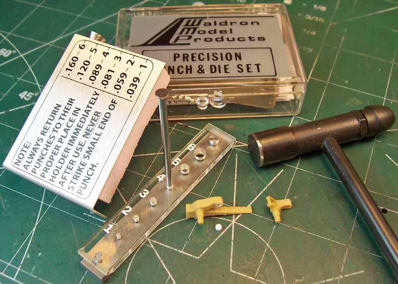

To be able to adapt the Tristar workable suspension to this kit I first had to bring down the inside peg hole diameter on the bogie wheel axle side of the assembled leaf spring suspension arms. The peg hole is to large in diameter for the peg on the kit suspension mount caps (A44 - Right Side and A45 - Left Side). I drilled out the holes on each of the leaf spring suspension arms to accommodate a styrene disk that I made from the #4 punch of the Waldron Punch & Die set.


After installing a styrene disk to each of the leaf spring suspension arms I drilled a hole in the center of the disk to accommodate the corresponding peg on the suspension mount cap. No modification was required on the bogie wheel axle side of the floating suspension arms.


On the bogie wheel housing mount side of both the leaf spring suspension arms and floating suspension arms I placed a styrene disk centered over the peg holes and drilled a hole in the center of the disk to accommodate the suspension mount housing pegs. The #3 punch was used for the disks on the floating suspension arms and the #4 punch for the disks on the leaf spring suspension arms.


There are two different diameter size pegs on the suspension mount cap that correspond with the pegs on the suspension mount housing to assist you with assembling the bogie suspension ensemble and keep it correctly orientated.


With the bogie wheel leaf spring suspension in the raised position.


And in the lowered position.
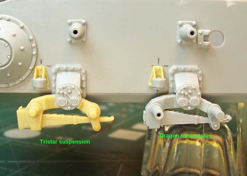

A comparison photo of the assembled Tristar workable bogie wheel suspension on the left and the kits non-working suspension on the right minus the end piece. Note the extra number of leaf springs on the kits suspension and the crisper detail.


An overhead view of the the bogie wheel suspension. The kits suspension arms are wider than the Tristar parts.


Bottom view of both the Tristar and kit bogie wheel leaf spring suspension assembly with the styrene disks on the housing mount side of the thinner Tristar suspension arms. The kits suspension parts better represent the robustness of the later designed suspension components to handle the higher overall weight of the heavier Panzer IV Ausf. F1 through G series of tanks. The Tristar suspension parts are better suited for the earlier series of Panzer IV tanks. At this point I have only test fitted the suspension components to the chassis for the photos and for anyone wishing to use the Tristar Panzer IV wheel set on their build using this kit. As you can see its workable! Now I'll have to decide weather to use the more accurate kit non-working suspension parts or the (you won't know the difference once the wheels are mounted) workable Tristar parts?


These are the tools, adhesives and finishing items that I used during this first installment of my build.

Any comments are welcome, thanks for stopping by and having a look - more coming soon!

-Eddy
Violetrock
Visit this Community
European Union
Joined: March 09, 2003
KitMaker: 831 posts
Armorama: 791 posts
Posted: Saturday, September 11, 2010 - 05:41 AM UTC
Saved.
alanmac
Visit this Community
United Kingdom
Joined: February 25, 2007
KitMaker: 3,033 posts
Armorama: 2,953 posts
Posted: Saturday, September 11, 2010 - 06:11 AM UTC
Hi eddy

Interesting post, very interesting.

I was wondering regarding the detail issue that you brought up. Don't get me wrong I'm not disagreeing with what you say or the examples given I just wonder if part of the issue is the colour of the plastic that Tristar use. Some of the detail gets kind of lost because of it and when you apply a coat of paint/primer then this may well come out much better if you understand me.

Having said that I think that second to Dragon putting great detail into their kits, the choice of grey plastic for their kits is spot on and really helps see the crispness of moulding they achieve.

Looking forward to the updates.

Alan

tread_geek
Visit this Community
Ontario, Canada
Joined: March 23, 2008
KitMaker: 2,847 posts
Armorama: 2,667 posts
Posted: Saturday, September 11, 2010 - 06:55 AM UTC
Hey Eddie, you are both a traitor to your callsign and the scale that it stands for. In all seriousness, you are doing an incredible job with this build log. You show the proper amount of OCD necessary for the extremely fine detailing that is being achieved. While not my preferred scale, I had to drop by and see what tricks you might have to pass along. I'm already thinking of seeing if some of these gargantuan techniques could be downsized to smaller scale.

BTW, the big win for me today was your hints and methodology about the use of gap filling super glue to deal with seems. In the past I've used Squadron putty with all its inherent quirks and limitations. My current build has several areas of gap issues that your methods may solve. Prior to writing this I put them into practice on some 1/72 fuel drums. After I finish this note I'll check and see whether it works as "advertised."

Good luck,
Jan
Braille
#135
Visit this Community
California, United States
Joined: August 05, 2007
KitMaker: 1,501 posts
Armorama: 1,485 posts
Posted: Saturday, September 11, 2010 - 11:50 AM UTC
Alan,

As I have the parts right in front of me I had to go and give the Tristar and Dragon suspension parts a second look. Actually to my eye IMHO the Tristar parts seem to have an edge over the Dragon parts in that the scale thickness appears to be a little better represented on the leaf spring detail and in a few other areas on the suspension. I have to agree with you about the color issue that you mentioned. I was looking at Frank Glackin's Tristar Panzer IV Ausf. D build log here before painting and here after painting where you can really notice the details that were hidden by the plastic color, not to mention Frank's uncanny skilled painting ability! I've also noticed that the yellow plastic color suffers when photographed in that it tends to keep the shadowing down preventing the sharp definitions that are easily captured with the gray plastic. My photos here are an excellent example of this!

Jan,

The 72nd scale stuff is still my preferred flavor although I will be venturing off from time to time with the larger scales. Hope that the super glue will work out for you. It takes a little getting use to but I like the end results. Just keep at it until you've managed your own method to the madness! Glade you could stop by and that you've gotten a little something out of my post. Almost everytime I open up and read through a posting here on Armorama I learn something new and thought why not share a little of how I put my builds together. I always learn something new from your postings.

Gentalment thanks for dropping by it is very much appreciated,
-Eddy
daffyduck
Visit this Community
United States
Joined: September 07, 2006
KitMaker: 164 posts
Armorama: 155 posts
Posted: Saturday, September 11, 2010 - 01:43 PM UTC
Excellent blog Eddy.....really appreciate your explanation for how you do it.

Nice project too.....

Regards, Paul
Braille
#135
Visit this Community
California, United States
Joined: August 05, 2007
KitMaker: 1,501 posts
Armorama: 1,485 posts
Posted: Sunday, September 19, 2010 - 12:19 PM UTC
Paul,

Thanks for dropping by . . . glade you you like it! Your comment is important in that it helps me to keep this build log going in much the same step by step fashion.

OK, Armorama Track-Heads,

Most of the major components that make up the lower hull have been added in my last posting now its time to move on to the upper hull . . .


In this view from step 10 I have installed the [50mm / 9 deg.] front armor plate (E14) to the upper hull (J1). My kit example had a few noticeable areas with shallow depressions on the appearance side of the armor plates surface so I lightly block sanded the offending areas smooth before installing the part. I've also gone ahead and added the two small (screw / rivet?) recess holes on the rubber bumpers that sit on the top front center section of each of the hatch splash-guards. I also removed a small portion of the rubber bumper near the bottom as these items do not run the full height of the splash-guard railing. The engine compartment section of my kits upper hull came slightly warped so I gently twisted the hull in the opposite direction a few times until the engine compartment section was level with the rest of the upper hull.


Here the left side upper hull [30mm / 0 deg.] angled single piece armor plate (E7) from steps 8 and 11 was then installed.


I removed the protruding vertical location bars for the jack block and filled in the location holes for the gun cleaning rod brackets and folding crew step ladder using either or both super glue and styrene rod in preparation of replacement photo-etched parts that I will be using. Also in preparation of a replacement photo-etched part the left side fender support bracket running along almost the entire length of the bottom side edge of the angled single piece armor plate was removed.


Before removing the 4 radiator air inlet grill lid latches, on the [20mm / 10 deg.] upper hull engine compartment left side armor panel, I drilled small holes through each of them to help me in placing the replacement photo-etched parts. I preformed the same operation on the right side radiator air outlet grill lid latches. The gun cleaning rod bracket location holes were also filled in.


Of the two alternative upper hull engine compartment rear armor panels provided in the kit, in the sub-assembly section of step 10, I chose the rear armor panel without the mounting brackets for the smoke discharge box. latter in the build I'll be putting together a replacement photo-etched smoke discharge box with mounting brackets. I removed the molded on main engine and turret power traverse motor muffler support bracket that spans the lower edge of the [20mm / 10 deg.] upper hull engine compartment rear armor panel (H19). Then the support brackets for the towing rope hooks were removed before I installed the panel to the upper hull.


View of the installed right side upper hull angled single piece armor plate (E6) from steps 9 and 11. The locating holes for the shovel brackets and vertical antenna storage case support braces have been filled in. Here also along the bottom side edge the right side fender support bracket has been removed.


Overhead view of the upper hull showing were I have removed three of the 7 sections of splash guards and the two door locks located on the center engine access hatch - more photo-etch replacements parts!


From step 7 I installed the engine compartment bulkhead (B24) to the lower hull. The kit supplied track fenders (K3 - Left Side and K4 - Right Side) come molded with the upper hull fighting compartment panels and because I will not be using these fenders I fabricated and installed two identical styrene panels to either side of the lower hull in order to fill in the void that will be left under the upper hull fighting compartment because of not using the kit supplied fenders.


Rear view of the upper hull and lower hull sections test fitted.


The upper hull and lower hull sections test fitted together to check the fit of the fabricated styrene fighting compartment panels.


I drilled a hole through the center of a styrene disk and then cemented the disk to the lower hull fighting compartment at approximately the center location to the turret ring opening of the upper hull. I then placed a nut over the disk and secured the outer sides of both the nut and disk to the hull with a two part 5 minute epoxy mix. I affixed a set screw to the end of a large sized X-Acto type blade handle to secure it to the lower hull. The small flat washer is for keeping the handle squared over the nut.


With this setup I will be able to conveniently hold the hull in any position during the upcoming airbrushing sessions.


On the hinge side I tapered the underside of both brake access hatches (A36) from step 5 because the hatches sat to high when installed on the front glacis plate opening causing a noticeable misalignment of the hinges. On the real tank both brake access hatches sat a little proud of the glacis plate but only on the edges furthest from the hinge. This is true for the F1, F2 and G series of tanks. However, I do not know if this occurred with any of the succeeding panzer IV's?


Before I installed the brake cooling air intake scopes (A41) from step 5 to the brake access hatches I thinned down the underside of the scopes to better match my photo references.


Here you can see the slight gradual rise, away from the hinge, of the brake access hatch when installed on the glacis plate.


In this view I have installed the engine starter crank handle port cover (E29) from the sub-assembled section of step 2 and both the fuel filler hatches (A26) from step 3 and from step 4 the cold weather heat exchange water pipe cover (H24).


The right and left side assembled and soldered Voyagermodel photo-etched towing cable holders.


Comparison views of both the kit towing cable holder (A27, A32 and A33 - Right and Left Side) and the 14 piece Voyagermodel photo-etched affair. Note that the Voyagermodel towing cable holder is a little wider and the cross section of the support plate is much thinner than the kits towing cable holders. There are several variations in the type of towing cable holders that were installed at the factory on the Ausf. F2's. The type of towing cable holder found in the Voyagermodel photo-etched set is more commonly seen on the earlier Ausf. D and E's. But I have also seen these same towing cable holders installed on F1's and on some very early F2's. With the limited references that I have on the panzer IV's I am hard press to find this type of cable holder on any of the G' series of tanks?


Both right and left side towing cable holders have been installed with super glue to there respective locations on the bow armor plate.


The three piece armor guard (A8, A9 and A10) assembly from the sub-assembly section of step 3 is now installed over both final drive / differential gear housings.


A photo of all the tools and supplies I used to solder and clean the towing cable holders. In the background you can see a rectangular piece of wood with a drill bit embedded in it. I used the drill bit to help keep the photo-etched parts aligned, on the piece of wood, while I hand soldered them together with solder paste. I will be able to explain this soldering method better through photos when I build the photo-etch fenders in a latter posting.

Any comments are welcome, and again thanks for stopping by and having a look - more on the way!

-Eddy
tread_geek
Visit this Community
Ontario, Canada
Joined: March 23, 2008
KitMaker: 2,847 posts
Armorama: 2,667 posts
Posted: Monday, September 20, 2010 - 03:23 AM UTC
Well written and very fascinating Eddy. Can't wait until you shrink down, climb in and take this baby for a spin. Also, can't wait to see you do the same with a 1/72 version.

Cheers,
Jan
Hederstierna
#247
Visit this Community
Nordjylland, Denmark
Joined: January 03, 2008
KitMaker: 1,102 posts
Armorama: 1,018 posts
Posted: Monday, September 20, 2010 - 03:27 AM UTC
Eddy
I did the same model and paintscheme a couple of years ago. It's a really cool kit just OOB, but I used some PE, though. Try the dry decals from Archer, they're great.
Maybe yuo'll get inspired from this.
Jacob


JimF
Visit this Community
Texas, United States
Joined: July 05, 2002
KitMaker: 717 posts
Armorama: 621 posts
Posted: Monday, September 20, 2010 - 06:03 AM UTC
Excellent SBS build blog you have going here. I really enjoy the clear pictures and explanations you are providing. Thanks!
Braille
#135
Visit this Community
California, United States
Joined: August 05, 2007
KitMaker: 1,501 posts
Armorama: 1,485 posts
Posted: Tuesday, September 21, 2010 - 09:01 PM UTC
Jan,
Thanks for the kind words . . . especially coming from someone as experienced with this sort of thing. My biggest motivation for attempting to do a build log here in the first place comes from the inspiration your excellent build logs, reviews and a very well managed campaign have given me.

A Braille build log? I'm going to have to give that a try. Perhaps a little after I finish with this build log? Jan, I don't know that I'll be able to shrink down anymore?

Jacob,
I sincerely appreciate you posting photos of your build. There's no maybe about getting inspired . . . I'll be looking at your build often! You've really captured the look of that tank. Great job on the camouflage and weathering. What colors did you use? I hope mine will turn out a 1/4 as good as yours . . . at least a 1/4! I've used the Archer dry transfer decals before but on a braille build and they worked out great. Do they make a specific set of dry transfers for this vehicle or did you have to piece it together from separate sets of transfers?

Jim,
Thanks so much for dropping by . . . I'm happy you like it. I really appreciate you stopping by and for your kind comments.

Gentlemen thanks so much for stopping by and for sharing your thoughts and input! I really appreciate you taking the time to check this build log out!

-Eddy
Hederstierna
#247
Visit this Community
Nordjylland, Denmark
Joined: January 03, 2008
KitMaker: 1,102 posts
Armorama: 1,018 posts
Posted: Wednesday, September 22, 2010 - 01:26 AM UTC
Hi Eddy
Glad I could help and inspire you. That's what this forum's all about. I've used Tamiya paint. I started by painting the model panzer grey and then randomly oversprayed it with a darkened dunkelgelb, so that the grey color is allowed to "shine" thruogh in some places. Yes, Archer makes a speciel decal set for this speciffic model, but I can't really remember the number, sorry!
Keep up the good work.
Jacob
spitfire303
Visit this Community
Vendee, France
Joined: December 22, 2006
KitMaker: 1,437 posts
Armorama: 1,406 posts
Posted: Wednesday, September 22, 2010 - 04:05 AM UTC
Hi Eddy,

Haven't seen you for a while here. It's a most impressive build you have here. I will watch closely.

cheers

spit
Braille
#135
Visit this Community
California, United States
Joined: August 05, 2007
KitMaker: 1,501 posts
Armorama: 1,485 posts
Posted: Friday, September 24, 2010 - 10:30 AM UTC
Jacob,
Thanks for the reply and especially the inspiration! As I haven't as of yet decided on how I will approach the paint scheme or with which brand of paints I will be using I just had to ask how you successfully arrived with your color scheme? I do appreciate you taking the time to share your brand of paint and mythology used in capturing on your kit the paint scheme of the kit box cover art. Don't worry about the Archer dry transfer sheet number. I was planing on paying there website a visit to get a few things there for this build. I'm glad you posted your tank here and let me know that they make as sheet specifically for this kit so I'll now be getting that too!

Pawel,
I'm so glad and happy that you could stop by to check out my first build log. Your build logs are extremely interesting and informative and I have learned so much from your postings. I haven't gone away, its just that now my SWMBO uses the computer too and that allows me only enough time to do some viewing. I have seen your recent posting and will drop by so expect to see me there!

-Eddy
Braille
#135
Visit this Community
California, United States
Joined: August 05, 2007
KitMaker: 1,501 posts
Armorama: 1,485 posts
Posted: Friday, October 08, 2010 - 11:16 AM UTC
Armorama Track-Heads,

Welcome back to this 3rd installment!


Step 10 gives you the option of selection between two alternate sets of lower air inlet / outlet horizontal support braces. I chose the lower air inlet / outlet horizontal support braces without the counter-sunk bolts (H44 - Right Side and H48 - Left Side). Designed for use on these parts from the Griffon Model photo-etch detail set, I installed all 8 air flow sheet metal panels to there respective locations on the two lower air inlet / outlet horizontal support braces using a slow setting gel super glue (gives me a little time for adjusting the photo-etch items on the kit parts). Care should be taken to make as smooth a curved transition on the photo-etched panel parts before installation onto the outer horizontal edge to the vertical back-wall of the kit parts. These panels were also installed without any curvature to them as seen on the PzKpfw. IV Ausf.G at the Nibit Research Collection, Kubinka, Russia. I don't have any specific information regarding the two types of lower air inlet / outlet horizontal support braces. Suffice to say that these parts may merely represent a production variance as these tanks were produced by several manufacturing plants?


These are the tools I used for installing the photo-etched parts to the lower air inlet / outlet horizontal support braces as well as the other photo-etch parts in this 3rd installment.


The left side simplified single horizontal bar air inlet grill (H38 - Left Side) with its lower horizontal support inlet brace from step 10 were cemented together and then from step 11 installed to the upper hull. Both my kits horizontal bar air inlet / outlet grills were a little short lengthwise so I filled the gaps with a mixture of Testors liquid cement and Squadron white putty applied with a No. 2 paint brush. I blended the mixture into the surrounding area and cleaned up any left over residue with only the liquid cement. The dry liquid cement (glossy surface) can be seen in the photograph.


I repeated the same procedure for the right side simplified single horizontal bar air outlet grill (H33 - Right Side) with its lower horizontal support outlet brace.


After installing both single horizontal bar air inlet / outlet grills with there lower horizontal support inlet / outlet braces to the upper hull I went to test fit the assembly to the lower hull and found that I could not get the two sections to fit together. I discovered that both lower horizontal support inlet / outlet braces were interfering with the engine compartment bulkhead. I quickly remedied this by removing a little material in the indicated areas shown in the photograph. Aside from this one issue the assembly and parts fitting together of this kit has gone very smoothly. At this point I don't know if perhaps I may have installed the air inlet / outlet grill assemblies incorrectly? But after removing material from the indicated area on both pieces the upper and lower hulls easily fall together without any noticeable gaps between them. So let's go on with the rest of this build.


From step 10 I've installed the radio operator's bow MG34 machine gun ball (G32) and ball mount (G31) [Kugelblende 50] to the front armor plate. Here is what I did to keep the machine gun ball free to rotate between the ball mount and front armor plate. With the machine gun ball installed inside the ball mount I held the ball mount against the front armor plate and lightly brushed liquid cement around the outer edge of the ball mount to seal it to the front armor plate. Then with a sewing needle chucked into a pin vise I carefully scribed a recess line around the inside outer edge of the ball mount.

With a file and sanding sticks, to smooth things out, I reshaped the driver's armor pivoting visor to better match my reference photos. After which the driver's armor vision port (G33) with the driver's armor pivoting visor (G34) [Fahrersehklappe 50] were cemented into place. Although not shown in the instruction sheet you have the option of placing the driver's armor visor in any position from open to closed. The visor was closed when entering a known battle zone at which time the driver relied on the KFF2 driver's binocular periscope (the two notched holes on the front armor plate, above the visor, are for the binocular periscope) and the vehicle commander (he had a better field of view of the outside through the cupola's 5 vision ports).


Then from step 11 a signal pistol port (D8) was cemented to each of the radio operator's hatch (D4) and driver's hatch (D5). I removed the molded on hatch locks on both the hatches then both hatches were cemented into there respective locations on the upper hull. Photo-etched hatch lock replacements from the Griffon Model full detail set were then super glued into place.


In this overhead view of the upper hull I have replaced the 3 triangular turret splash guards that I had removed in the 2nd installment with those from the Voyagermodel basic photo-etch set. And the two molded on hatch locks on the center rectangular engine access hatch that resides between the radiator and cooling fan hatches were replaced with photo-etch hatch locks from the Griffon Model full detail set.


On the upper hull engine compartment rear armor panel I have replaced the support brackets for the towing rope hooks, that were removed in the 2nd installment, with photo-etch replacements from the Voyagermodel basic photo-etch set. Behind the thin photo-etch support brackets I used sheet styrene to bring them to a better scale thickness. Because I thought they seemed a little to flimsy I went ahead and replaced the kits towing rope hooks (A52), from step 10, with steel rod. As an added note the upper rear hull armor plate could be unfastened to allow for engine changes or heavy maintenance servicing.


The driver's side vision port structure framing (G20) for the internal armor glass and shutter flap hinge assembly (G10) from step 8. To keep the shutter flap hinge assembly movable I took care to allow the liquid cement to make contact with only the vision port structure framing and left side upper hull angled armor plate. I repeated the same process for the radio operator's side vision port structure framing (G20) and shutter flap hinge assembly (G25) from step 9.


And then back to step 8 again for installing the armor outlet cowl (B15) to the forward left side upper hull angled armor plate.


Preparing to tackle some photo-etch parts. The main interest in this photo are the X-Acto blade handle with the Number 17 blade, the stamp collectors wide faced tipped tweezers and the small 4.5"L x 5"W x 3/4"H (114.3mm x 127mm x 19.05mm) square wood kitchen cutting block. Tamiya produces a nice selection of low tack masking tapes that range in sizes from 6mm to 40mm. This masking tape is my favorite because of its very low tack adhesiveness making removal easy without pulling the paint away from the surface of your model. I use this tape when working with photo-etch parts because I won't run the risk of bending the parts when I remove the tape and yet it will hold the parts firmly enough for me to form hinges on even the largest parts.


Here is the coolant cap cover (H42) from step 10 with the photo-etch cap cover hinged hatch, hinge rod, hinges and hatch lock from the Griffon Model full detail set.


In this photo the hinges have already been formed. Let me explain how I went about doing this. First I added just enough bend to the hinges to be able to get the X-Acto blade beneath them when it came time to forming them. I then placed the Griffon Model suggested diameter brass rod against the edge of the cap cover hatch and secured it with masking tape. Then I secured the cap cover hatch with masking tape to the wood block. I then slightly kinked the edge of the hinge in the direction of the cap cover hatch. While holding the brass rod with tweezers to keep it against the edge and from moving on top of the cap cover hatch I placed the X-Acto blade underneath the hinge and carefully warped the hinge over the rod until almost reaching the cap cover hatch. I now swapped tools and used the X-Acto blade to hold the brass rod in position and the tweezers to form the hinge. With the flat head tweezers I applied steady pressure to the hinge while at the same time keeping the hinge against the rod. At some point while applying a steady increase in pressure the hinge will suddenly collapse and wrap itself around the brass rod. Bang . . . hinge formed!

Yes, its as easy as that. Sometimes the hinge won't form properly and you'll have to straighten it out for another try. But once you've formed your first hinge your on your way! I then proceeded to form the rest of the hinges following the same procedure with the same set up. Then removed only the tape holding the brass rod and with a set of stainless steel wire cutters I cut the brass rod in two near the center of the hatch. I slide each piece away from each other and placed a tiny drop of super glue on the rod nearest the hinges of the hatch and then slide the rod into the hinge leaving the inside hinges free of super glue. I placed some super glue accelerator on the glued hinges with a micro brush. Finally I cut the rod flush against the hinges. I carefully removed the taped hatch and made sure that the inside hinges would not fall off and put the hinge aside for the next step.


After cutting away the hatch lock I flat sanded the hatch off of the coolant cap cover using an 8 pattern against a small sheet of wet or dry 360 followed by 400 sand paper. I checked my process along the way until the hatch was entirely removed. I then centered the photo-etched hatch assembly over the coolant cap cover and secured it with a small strip of tape. With a sewing needle I placed a tiny drop of super glue on the free moving hatch hinges and set them against the coolant cap cover. I used a little extra super glue around the edges of the hinges to simulate weld and I placed some super glue accelerator on these hinges with a micro brush. The hatch lock was then added to the hatch. Ka-boom . . . workable hatch! So if a caveman can do it, so can you!


On this build I'm securing the hatch to the coolant cap cover with super glue. But I wanted to show you how I arrive at making the hatch hinges workable should you not already know or have been a little hesitant to try your hand at working with these small photo-etched parts?


Next I super glued the armored louvered grill (MA24) to the cooling fan access hatch (H22) and armored louvered grill (MA25) to the radiator access hatch (H21) from step 10.

The armored louvered grills are optional parts. By design the lower set of armored louvered grill gills don't seal off the engine compartment as these are offset from the top louvered grill gills only enough to keep overhead air burst sharpnal, metal fragments and debris from directly entering the engine compartment. In 1942 on the Ausf.F2 and G's the louvered grills were introduced as standard and fitted onto both the cooling fan and radiator access hatches. Prior to this the louvered grills were fitted to the Ausf.F1's and proceeding models but only on the tropical version. The louvered grills were installed recessed on the access hatches on the Ausf.F2's and G's and sat proud on the previous models.

At what point were the lower louvered grills installed I do not know? I went ahead and installed them anyway. When I went to test fit the access hatches to the upper hull I discovered that both access hatches sat proud of the upper hull so I used a small flat file to remove material along the inside edge of both access hatches until they both sat flush on the upper hull. I then installed both access hatches.


And here from step 10 the coolant cap cover has been installed onto the radiator access hatch and also the hatch handle (A47) to the cooling fan access hatch. I replaced both rivets on the hatch handle with styrene disks as the molded on ones were compromised during the clean up. The hatch locks on both access hatches were replaced with those from the Griffon Model full detail set.


From the sub-assembly section of step 10 is the kits MG34 machine gun feed and barrel assembly (J28) together with Lion Mark's brass barrel and armor jacket for the MG34. Also a small styrene strip guide that will be lost when I remove the kits single part barrel with jacket to accommodate the Lion Mark pieces.


As a precaution note how the kits barrel and armor jacket are orientated to the feed assembly of the gun before removing. At almost the end of the Lion Mark's brass barrel that faces the feed assembly there is a small raised ring around the barrel to both help center the armor jacket over the barrel and rest against the feed assembly. After removing the kits molded on barrel with armor jacket I carefully sanded the area flat with a sanding stick and then drilled a .020" (0.508mm) hole in the center deep enough to allow the brass barrels raised ring to come in contact with the feed assembly.

I then placed the armor jacket over the brass barrel and applied a tiny drop of super glue to the inside of the drilled hole on the kits MG34. I carefully mated the assembled barrel with armor jacket to the feed assembly. With the barrel assembly set in place the armor jacket can now be rotated around the barrel to properly orientate it. My armor jacket was held firmly enough against the feed assembly by the barrel after adjusting it so I did not use any super glue to set it. I then set the styrene strip guide into place along with the trigger and hand grip assembly (J27).


A view with the assembled MG34 machine gun and machine gun ball spacer (J20), from the sub-assembly section of step 10, installed.


The 90mm armor vision glass blocks (M2 to M5) with all of the support sprues connecting them together removed.


I dipped the armor vision glass blocks into a mixture of Future and green food coloring. I used several drops of the food coloring to achieve the color that I was looking for but you could apply as much as you want to suite your preference. If you don't already know about Future here is a link that will give you all you need to know about this product.


The armor vision glass blocks after dipping them in the Future and green food mixture. As the Future sets up over several days the color will fade away leaving just a hint of the green color. Note the high crystal clear shine after dipping the parts into the Future.


After allowing the Future to set up over several days I set about masking the viewing areas of the armor glass blocks. I used a set of dividers to transfer the widths and lengths onto the masking tape. A 6" metal scale was used to both guide the X-Acto blade and keep it headed in a straight line while cutting the masking tape. The tweezers where used to place the cut pieces of masking tape over the viewing areas of the armor glass blocks. Scissors and cutting tweezers were used to make fine adjustments on the masking tape. And a chisel tipped toothpick was used to burnish the tape down onto the armored glass blocks.


Both sides of the viewing area on the armored glass blocks taped up ready for some paint.


Here I've airbrushed the unmasked areas of the armored glass blocks with Tamiya's acrylic clear green.


Then I over sprayed the clear green with Model Master's acrylic Panzer Interior Buff. No, its not your eyes the photo is blurry!


I still haven't decided if I will display either of the side vision ports open so while I already had the airbrush loaded with the Panzer Interior Buff I went ahead and sprayed both vision port structure frames and shutter flap hinge assembly's just in case I do. I first airbrushed the interior.


And then the exterior. Oops! Note the paint build up around the edges of the tape. Applied to much paint without allowing the first coat to dry sufficiently enough.


Let's not forget the interior side of both the side vision port armored shutter flaps (G22).


After a few hours of drying I removed the tape to check out how the armored glass blocks looked. The Future and green food color mixture is hardly noticeable in the photos but you can notice the faint green tint in person. By painting the sides of the armored glass blocks clear green I am attempting to simulate the color that armored glass reflects when viewed at certain angles. Depends on your preference as to how much color if any you may choose to use but I like the results that I was able to achieve on my first attempt. I may go back and add a Future mixture of green and blue to the inside of the viewing blocks?


The left side vision port after cleaning and leaving only enough paint to be hidden under the armored shutter flap. I had carefully removed the excess amount of paint with a cotton swap moistened in Mr. Color Thinner. After allowing the paint to dry and thinner to completely evaporate from around the vision port I gently rubbed the area with 0000 steel wool to blend the edges of the paint into the bare plastic.


Here I have given the Panzer Interior Buff a Sin Industries filter wash of Brown for Dark Yellow to age and tone down the color.


With the exception of the Mr.Color Thinner (not shown) here are the paint mediums that I used for this installment.


The MG34 machine gun installed. I first cemented the MG34 machine gun assembly's ball spacer to the machine gun ball and waited until the cement became tacky so that I could align the machine gun to the ball mount when viewed from the business end of the gun. I then secured the machine gun ball spacer to the machine gun ball with super glue in the indicated areas. Then the upper hull 90mm armor vision glass blocks were then installed into there respective locations.


Finally I installed the upper hull to the lower hull . . .


An overhead rear view of upper hull with the installed radiator access hatch (Left Side) and cooling fan access hatch (Right Side).

Any comments are welcome, and again thanks for stopping by and having a look - more on the way!

-Eddy
acebatau
Visit this Community
Colorado, United States
Joined: February 10, 2008
KitMaker: 730 posts
Armorama: 616 posts
Posted: Friday, October 08, 2010 - 12:15 PM UTC
Wow! What a project keep it coming! Thanks for detailed photos. Realy nice.
Cheers!
Braille
#135
Visit this Community
California, United States
Joined: August 05, 2007
KitMaker: 1,501 posts
Armorama: 1,485 posts
Posted: Sunday, October 17, 2010 - 12:23 PM UTC
Batsaikhan,

Thanks for stopping by and having a look. Glad to hear from you - helps me to stay motivated. Sorry about the long delay in replying to you . . . work stuff and viewing other projects, campaigns here! So many builds to see here on Armorama. Also been working on the photo-etch fenders - very time consuming. Will post as soon as I get finished with that part of the project.

Again, thanks for stopping by . . . much appreciated.

-Eddy
acebatau
Visit this Community
Colorado, United States
Joined: February 10, 2008
KitMaker: 730 posts
Armorama: 616 posts
Posted: Sunday, October 17, 2010 - 02:06 PM UTC
You're welcome Eddy,

I'm planning to do something like yours in the near future, just collecting all the detailing AM parts.
Keep up the good work! It's so inspiring!
Braille
#135
Visit this Community
California, United States
Joined: August 05, 2007
KitMaker: 1,501 posts
Armorama: 1,485 posts
Posted: Saturday, November 13, 2010 - 10:56 AM UTC
Armorama Track-Heads,

Sorry about the long delay in posting an update. This was due in part to a tedious work schedule, fighting a head cold and plenty of honey do's (no choice)! Anyhow here is the 4th installment . . .

This entire installment deals with putting the Griffon Model Panzer IV Ausf.F/G photo-etched fenders together. The supplied kit fenders are extremely well detailed and very accurate but I just couldn't resist pimping out this Panzer IV with a set of photo-etch fenders. Here's what I was in for . . .

Before I go on there are a few things that you should know when working with photo-etch parts so I'll list these here.
* Safety glasses - need I say more?
* Good lighting.
* Optical head gear or reading glasses with at least a 6-8" (152.4-203.2mm) focal length. 2.75 times magnification = 6" / 2.5 times magnification = 8" or a little less magnification depending on what your more comfortable with using.
* Photo-etch hold and fold tool.
* Bending pliers.
* Stamp collection pair of flat nose tweezers (at least two pair).
* Painters blue low tack masking tape or Tamiya tape.
* Small wood cutting block.
* Good quality super glue or an acrylic hobby glue such as Gator's grip.
* Patience and practice (lots of both and not sold in stores).
* The ability to sit on your butt for long stretches at a time . . . and keeping cold beer within arms length.
* Did someone mention soldering?

After studying the Griffon Model track fender instructions I noticed that I would need to add a .020" (0.508mm) thick piece of styrene sheet to both sides of the bottom sections of the upper hull superstructure that overhang the lower chassis because the lower air inlet / outlet horizontal support braces sit .020" lower than the upper hull. Adding a .020" thick styrene sheet panel would keep the fender bracket parallel with the upper and lower hull without creating a rather noticeable gap between the installed assembled fenders and upper hull. This is not mentioned in the Griffon instructions. Here's how I set about making the styrene sheet panels for both sides of the upper hull superstructure.


After cutting two .020" styrene sheet panels at approximately the needed width and length I placed each piece against the bottom of the upper chassis and with a felt tip pen marker I roughly marked the area that will need to be trimmed away.


Using a 6" (152.4mm) metal scale I joined the dashed outlines with the pen marker.


Again using the 6" metal scale as a guide I carefully placed the scale on the inside of the marked lines that will become the panel and scribed the styrene sheet with a P-Cutter. The reason for placing the scale on the panel side of the marked line is because the P-cutter will remove approximately a .015" (0.381mm) wide section of material when scribing.


After a few light passes with the P-Cutter I was able to bend and snap the styrene sheet panel by hand along the scribed line.


Instead of bending and snapping off the styrene sheet panel as before I used a pair of scissors along the scribed line to aid me in keeping the angled edge from breaking off with the rest of the styrene sheet as that narrow section is very weak.


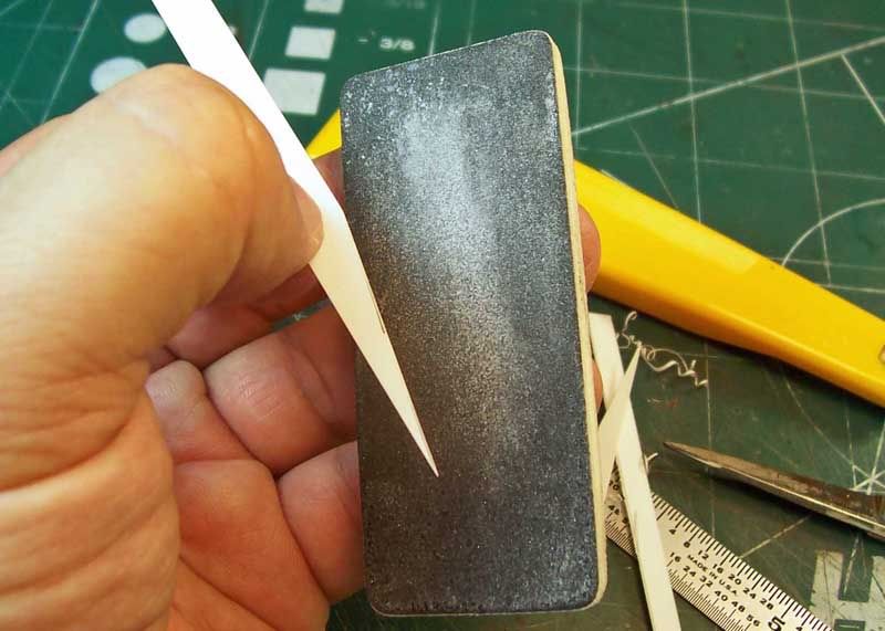
The styrene sheet panel scribed edges were then sanded square with a course grit wet or dry sanding pad.


Both panels were then cemented into place. Final trimming and sanding could then be made after the panels have had a chance to cure overnight. Here you can see how the lower air inlet / outlet horizontal support braces sit below the upper hull sides and into the lower hull.


I use a micro chisel, a small hobby hammer and wood block to remove the photo-etch parts from the fret. The wood block helps keep the chisel tip from dulling and allows the photo-etch part to be easily removed from the fret. With the micro chisel I try to cut at the brass sprue as close to the fret as possible to keep from bending the part during removal. On very small parts I often place low tack masking tape across both the part and the fret, leaving the sprue exposed, in order to keep the part from launching into the air and possibly not finding the part again!


I then remove the brass sprue with a pair of stainless steel scissors.


On areas that are non-accessible to using a pair of scissors to remove the brass sprue I use a pair of carbon steel side cutters. This tool is rather expensive at almost the cost of two $35 Dragon 35th scale kits. But will cut through plastic and photo-etch parts like a hot knife through warm butter without dulling. I have had my pair for over 20 years and its still as sharp as the day I bought it! Just don't use them for metal or steel wire. It's one of the most useful tools that I have for modeling.


No matter how careful you try to be with removing the brass sprue there's going to be a few nubs left here and there. These nubs are easily removed with a medium grit sanding stick. Note the small protruding nub on the right side of the part just above the sanding stick.


After a few light passes with the medium grit sanding stick . . . where's the nub?


These are the tools that I normally use to remove and prep the brass photo-etch parts.


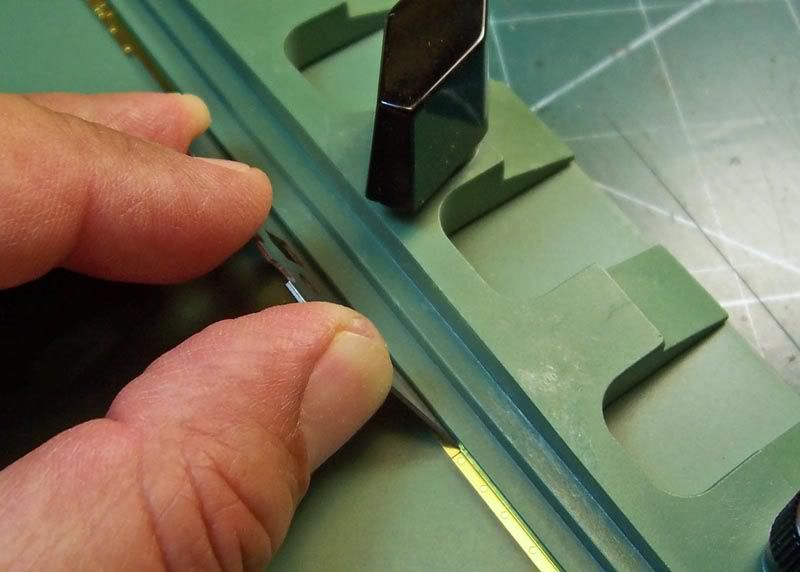
Now on to the folding! Most photo-etch folding tables come with a few folding blades. Mine are made of plastic and for the most part they work fine. However I like to complement these with a cutting blade made of metal. By placing the cutting edge of the blade into the photo-etch folding channel this allows me to place the photo-etch part right up against the folding finger(s) just above the V groove folding channel. The V groove folding channel is on the folding table. Incidentally, the table sits a little higher on the folding finger(s) side of the V groove thus allowing you to place the folding blade beneath the photo-etch part and using the V groove to maintain the blades edge against the folding finger(s) while bending the photo-etch part . Ohhh, I'm out of air!


While still holding the part in place against the folding finger(s) your then able to secure the folding finger(s) over the part while at the same time keeping the part aligned with the V groove folding channel. Here you can see I'm not quite lined up yet, as the photo-etch folding channel is at a slight angle away from the folding finger.


OK! Now the photo-etch folding channel is lined up with the folding finger and secured.


Here you can see that the photo-etched part is now folded and ready for use.


If working with photo-etch parts is not hard enough lets do some soldering! I use a combination of adhesives to secure the photo-etch parts together. I also use solder for those areas that will require a really strong bond. With the fenders hanging off to the side of the vehicle with loads of tools and mud flaps I thought it best to bond the fender brackets together with solder.

Here you can see that I'm using a thin wood block and some craft needles as a fixture. A set of flat nose tweezers to hold the parts together and a non-adjustable temperature controlled soldering iron for a heat source . . . nothing special or expensive here! Soldering is not that difficult to do as I will explain my method while doing the hinges on the mud flaps.


Both fender support brackets with supporting braces now soldered without the heat marks and solder spills on the parts . . . 'How did he do that?'


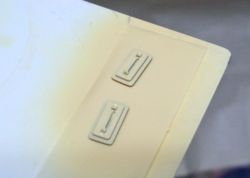
I had to fabricate a small angled photo-etch part to secure both small curved fender extensions as these are not supplied in the kit. This is the tiny part that holds the curved end fender extensions on both fender brackets in the center of the photo.

I had also soldered the joining sections of the curved fender extensions after folding them. I first added a little liquid solder flux into the inside area of the curved folded section and then placed the hot soldering iron against the outside edge of the curve and with a piece of .010" (0.254mm) diameter solder I flowed the solder from the inside to the outside edge thus filling the joining curved sections together. The molten solder will always flow in the direction of heat. I then sanded the excess solder on the outside edge with a medium sanding stick.


A comparison shoot of the kit supplied left side fenders with brackets and the Griffon photo-etch fender brackets.


A close up of the same fender bracket near the front of the fender.


Here I've folded the rear mud flap fender plate and hinges.


Here I'm using the suggested .020" (0.508mm) diameter brass rod to temporarily assemble the hinges to the rear mud flap fender plate.


Here's how I solder these photo-etched components together . . . are we paying attention? First I place a tiny amount of liquid solder flux to the areas that I will be soldering and allow the liquid solder flux to become tacky. Next I apply a small amount of solder paste using a micro spatula. I then allow the solder paste to mix in with the liquid solder flux.


Now it's time to do some soldering. I place the parts to be soldered together using either tweezers or a heat sink and then using the soldering iron as a heat source I wait until I see that the flux gasses (smokes) and the solder goes from dark gray to a shinning silver. I quickly remove the soldering iron and wait for the parts to cool for a few seconds while still holding them together. Bamm . . . nice solder joint.

If the joint is not were you want it to be simply add a little liquid solder flux to the area, reheat with the soldering iron and move it where you want it. It's that easy.


Remove any liquid solder flux residue from the parts using either Isopropyl alcohol or warmed up rubbing alcohol with a brush. You don't want to leave any flux on the parts because the flux is very corrosive and will easily eat through your paint job. And wash your hands before eating anything after coming in contact with the liquid solder flux and solder paste.


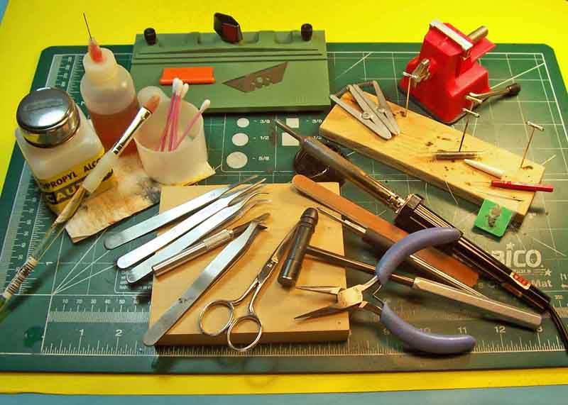
Here are all of the tools and items used to remove, prep, clean, fold and solder the photo-etch fender brackets.


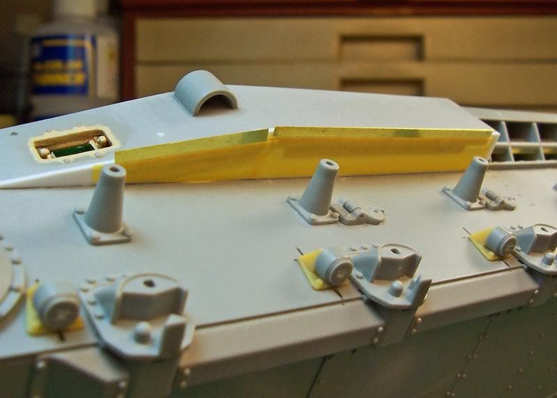
I made a couple of fixtures out of the photo-etch fret to use as a means to have the upper hull side fender brackets sit just below the edge of the upper hull side armor plate the same thickness as the photo-etch fender bracket.


The photo-etch fixtures fixed in place.


Bottom view of the photo-etch fixtures affixed with Tamiya low tack masking tape to the bottom of the styrene sheet panel.


I first affixed the side fender braces to the upper side armor plates and then the soldered fender brackets to the upper hull bottom superstructure plates and lower hull sides using Gator's grip glue and allowed the glue to set up overnight before proceeding. Here you can see that the side fender braces sit on the same plane as the outside fender brackets.


Forward view of the installed fender brackets.


Bottom view.


Next I affixed the soldered photo-etch fender, main engine and turret power traverse motor muffler support brackets to the rear of the upper and lower chassis with Gator's grip glue and again allowed the glue to set up overnight.


I then placed both the rear most tread plates on the inner fender brackets and fender, main engine and turret power traverse motor muffler support bracket again with Gator's grip glue and allowed the glue to set up overnight. I was then able to affix the outer fender brackets to the rear most tread plates. Then the two rear fender support brackets and then the rest of the fender tread plates were installed with Gator's grip glue.


Then came the front left side fender support bracket.


Followed by a pair of .005" (0.127mm) thick styrene front mud flap rubber dampers to each front fender section. And fender spring retainers (I don't remember the disk sizes used but the rods are .025" (0.635mm) diameter).


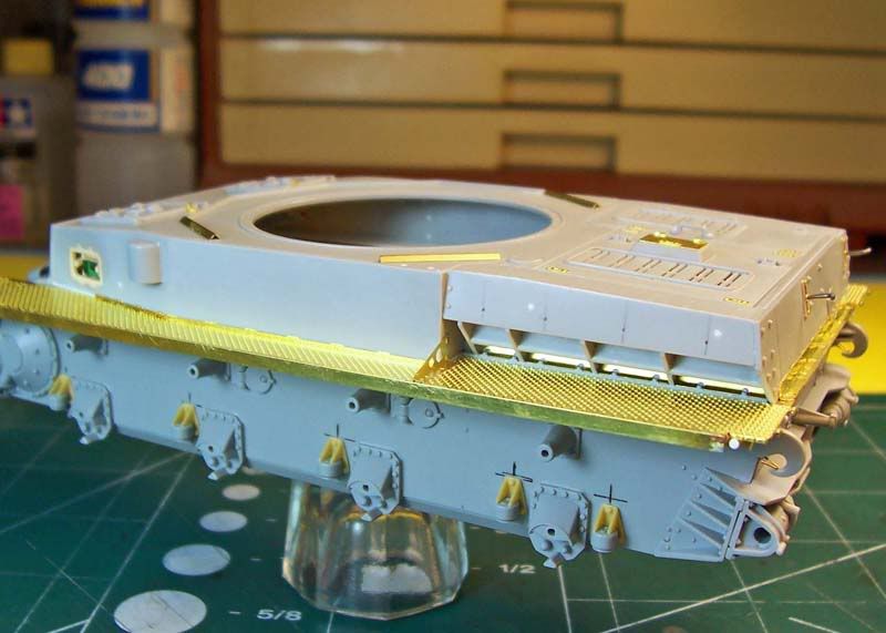
Overhead view of the completed photo-etch fenders without the mud flaps installed.


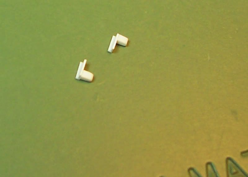
And here are the two small pieces that I fabricated from sheet styrene after losing the molded on pair during removal of the main engine and turret power traverse motor muffler support bracket in the first installment of this build log.


I don't know what the two small pieces that I fabricated are suppose to be there for but here they are installed over the towing hooks in the same locations as there molded on counterparts in this rear view of the main engine and turret power traverse motor muffler support bracket. I also used four of the Verlinden resin nuts on the same bracket.


Left side view of the completed fenders.


Right side bottom view.


Left side bottom view with the kit supplied fender for comparison.


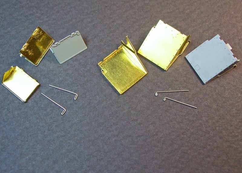
The completed front and rear photo-etch mud flaps and soft metal hinge rods with the kit supplied mud flaps for comparison. I formed .020" (0.508mm) diameter soft metal rod and attached them around the lower edges of the mud flaps with super glue to represent the reinforced mud flap fender rods that were brazed to the edges of the real sheet metal mud flaps.


Finally the adhesives used to install, attach and assemble the photo-etch fenders. Not shown is the No. 11 X-acto blade and handle that I use as an applicator for the super glue.

Any and all comments are welcome, and again thanks for stopping by and having a look - more on the way!

-Eddy
maartenboersma
Visit this Community
Noord-Holland, Netherlands
Joined: October 10, 2010
KitMaker: 764 posts
Armorama: 742 posts
Posted: Saturday, November 13, 2010 - 11:17 AM UTC
TOP!!
Plasticbattle
#003
Visit this Community
Donegal, Ireland
Joined: May 14, 2002
KitMaker: 9,763 posts
Armorama: 7,444 posts
Posted: Saturday, November 13, 2010 - 11:45 PM UTC
Fantastic build blog so far Eddy. Great attention to detail, and all done so very neatly. Looking forward to more!
tread_geek
Visit this Community
Ontario, Canada
Joined: March 23, 2008
KitMaker: 2,847 posts
Armorama: 2,667 posts
Posted: Sunday, November 14, 2010 - 04:06 AM UTC
Eddy, you've obviously gone FAR beyond a build log. This project has got the makings of the "Mother of All Features." Having seen a few printed books detailing the building of a specific model subject, what you have here easily matches and in many cases exceeds them.

Cheers,
Jan
BBD468
Visit this Community
Texas, United States
Joined: March 08, 2010
KitMaker: 2,465 posts
Armorama: 2,383 posts
Posted: Sunday, November 14, 2010 - 08:21 AM UTC
Hi Eddy,

this is a great build Eddy, very inspiring! i suck at soldering . you make it look so easy. exactly what type of solder and flux do you use and where can i purchase it myself? you mentioned paste and it looks much easier to use.


Gary
Braille
#135
Visit this Community
California, United States
Joined: August 05, 2007
KitMaker: 1,501 posts
Armorama: 1,485 posts
Posted: Sunday, November 14, 2010 - 11:26 AM UTC
Maarten, I'm glad you like this build log. Welcome to Armorama, there are so many knowledgeable and skilled modelers here, from novice to professional on this site with a great staff to help you out with any modeling question you may have, so here's hoping you'll like and enjoy it here. Hope to see some of your work here too!

Frank, I admire your build logs and you are correct in that it takes a great deal of time in writing these build logs and that of course includes editing all of the photos to convey the correct idea to every viewer . . . what have I got myself into? Your also correct about this being a high quality kit and not really needing all of the bling, but I just couldn't resist!

Jan, your no stranger to posting build logs here either. I do admire your patience, professionalism and great sense of humor. I still need lots of work on all of these treats especially on the last one. Thanks for your kind words and support.

Gary, I use a rosin base liquid flux and .010" diameter SN63 low temperature flux core lead based solder both of which are readily available at Fry's Electronics or Radio Shake. The liquid flux comes bottled and the lead based solder comes on a small spool. The stuff should last you a lifetime and the solder could be used for modeling electrical lines, conduit, spark cables, hydraulic tubing for aircraft landing gear, etc. You should be able to get the stuff cheaper online. I believe for the solder paste you may only be able to get that stuff online as a mixable two part compound, but I could be wrong it may also be there in the stores too. The solder paste that I am currently using is the refrigerated type used in the electronics industry for soldering surface mount components to printed surface boards when run through a flow solder machine. It has to be kept refrigerated until use but the mixable type works the same and has the added advantage of letting you measure the amount you need thus allowing you to keep the rest of the compound stored in a cool dry place until you need to mix up a new batch. The solder paste shares the same melting point as the solid solder. Just remember that a little goes a long way. I don't recommend using the water soluble type of solder as it dose not share the same holding power and is somewhat brittle when it solidify s. I know, I've been soldering professionally for over 40 years now. The hardest part of soldering with the photo-etch is finding the best way of holding the parts together. I check the temperature of the soldering iron tip on the wood, when it leaves a burn mark on the wood when you lightly hold the iron against it - its ready. It should only takes a few seconds with the iron against the photo-etch parts to get the parts hot enough to let the flux clean off any oxidation and liquefy the solder or solder paste. Just try it out on some photo-etch frets first. You can do it, it's that easy! Hopes this helps you!

It's these kind of comments that all of you have taken the time to post here that remind me to stay focused on providing as much information to the viewer on this very time consuming step by step project. Thanks for stopping by, I sincerely do appreciate it very much!

-Eddy
BBD468
Visit this Community
Texas, United States
Joined: March 08, 2010
KitMaker: 2,465 posts
Armorama: 2,383 posts
Posted: Monday, November 15, 2010 - 02:17 AM UTC
Hi Eddy,

Thanks so much for your detailed responce. i think ive been useing the wrong kind of solder. there is a Fry's & radio shack within 15 miles of my house so i can address the issue at once. Thanks again Eddy!


Gary
 _GOTOTOP