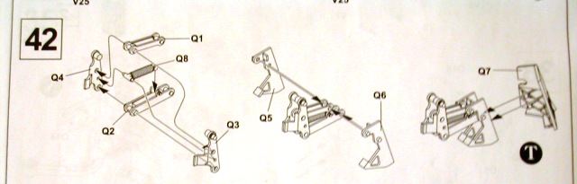
Here you assemble and install what I will call the 'engineer rack'. It is an extension that protrudes out above the rear ramp and provides additional storage space for engineer sets, kits or outfits. This extension is unique to ESV's.
The step is broken down into four sub-steps.
This step, overall, took the most work on the kit so far as a result of there being so many ejector pin marks.
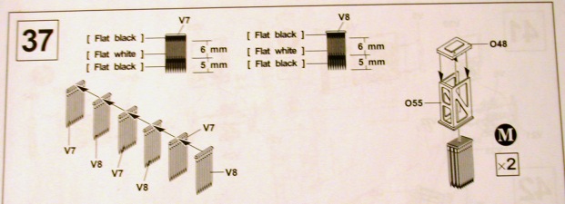
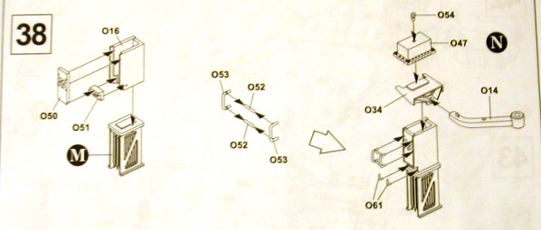
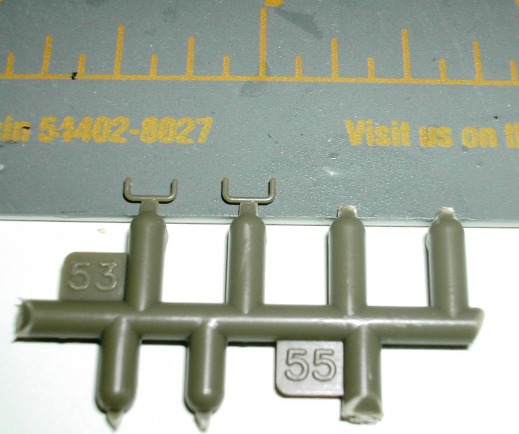
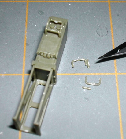
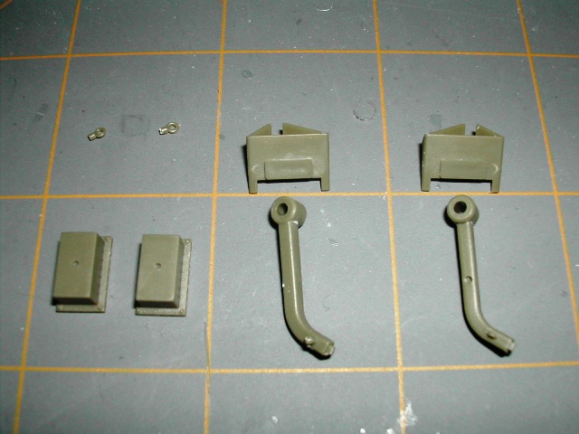
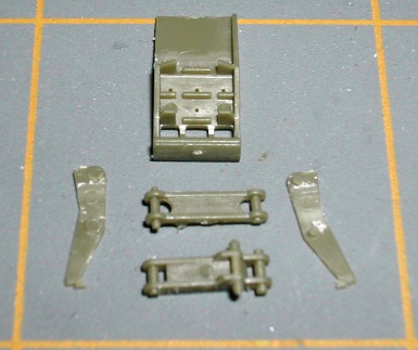
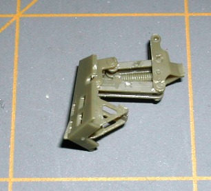
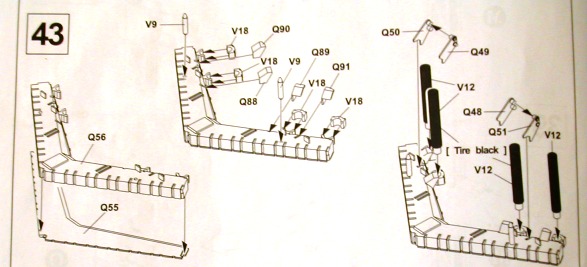
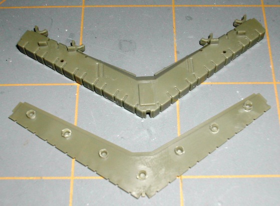
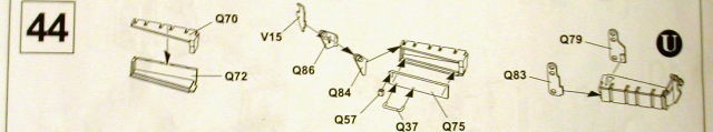
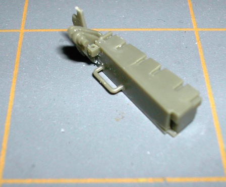
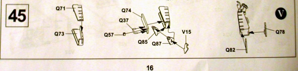
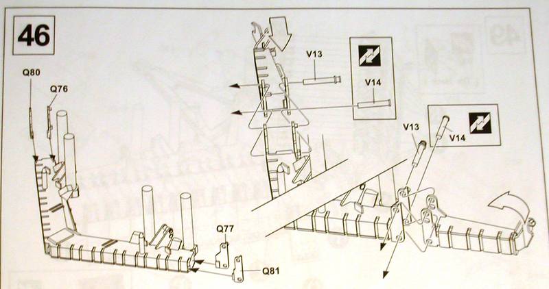
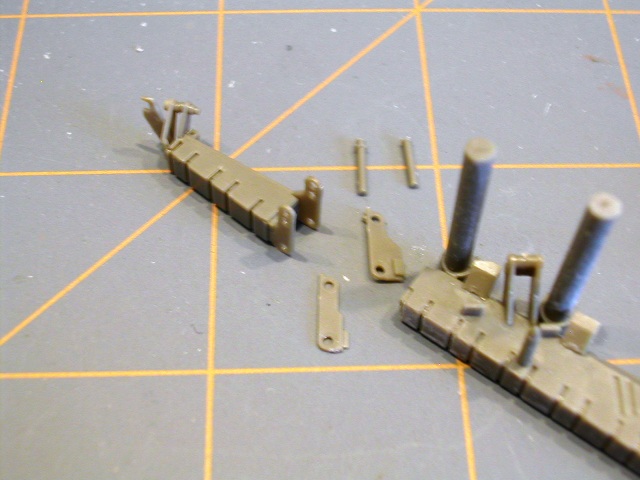
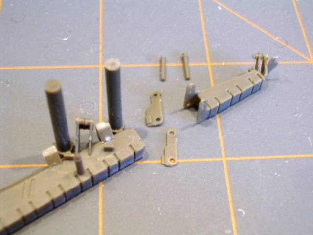
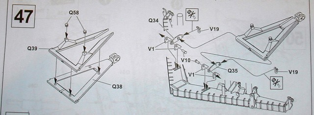
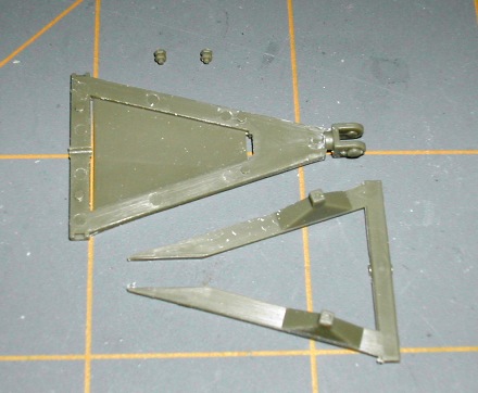
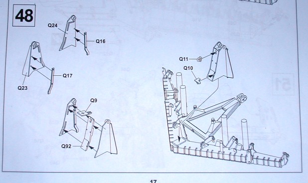
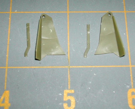
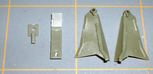
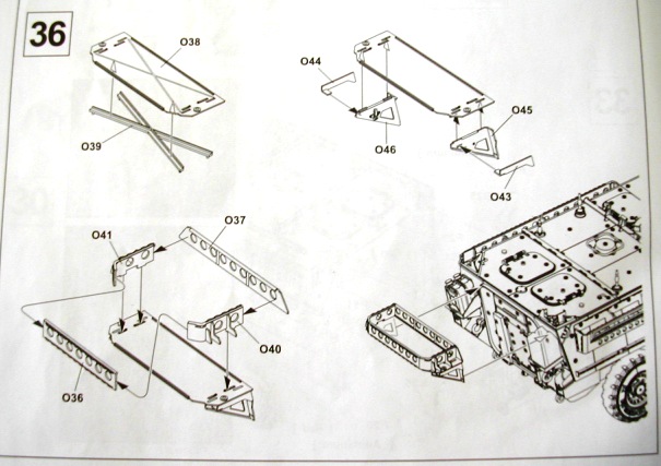
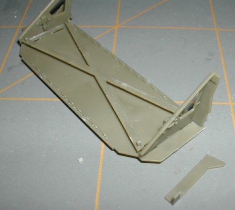
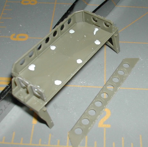
Sub-step 1 has you installing a reinforcing cross member to the bottom of the 'engineer rack'. Here is the parts layout.
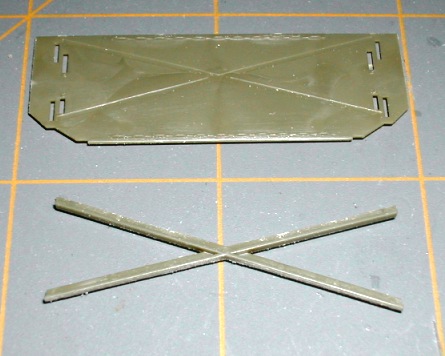
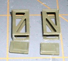
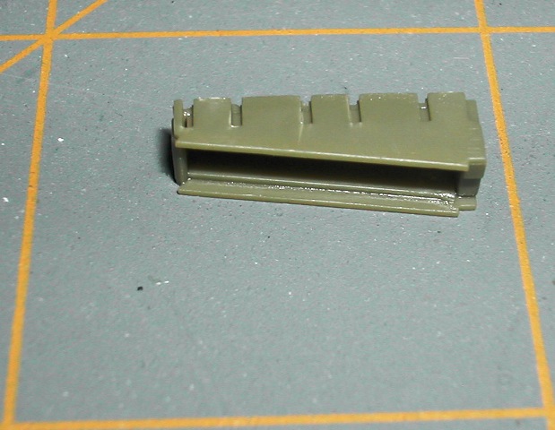
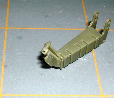
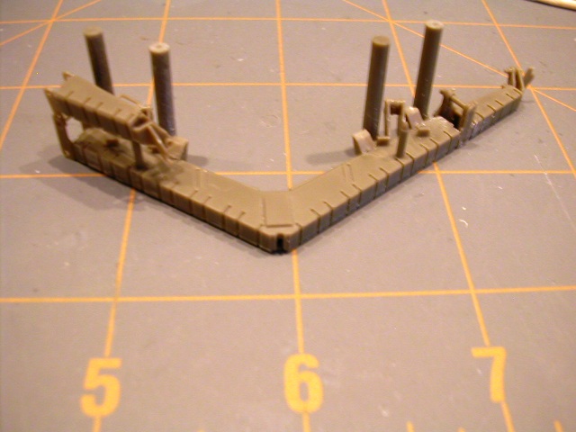
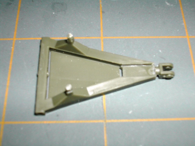
Here are the parts in place.

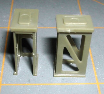
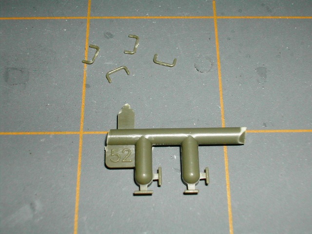
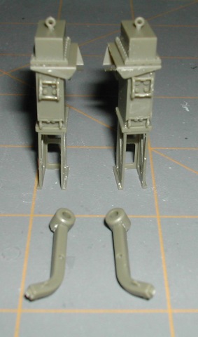
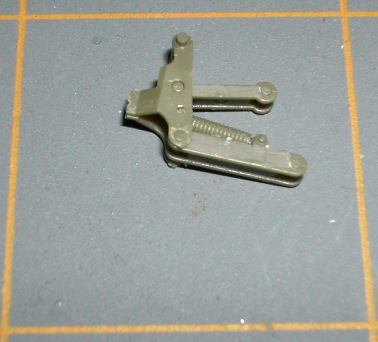
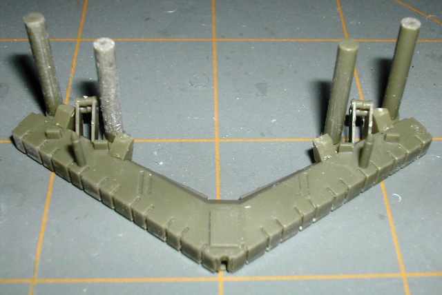
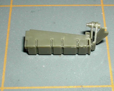
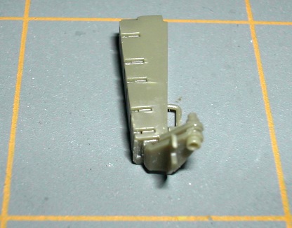
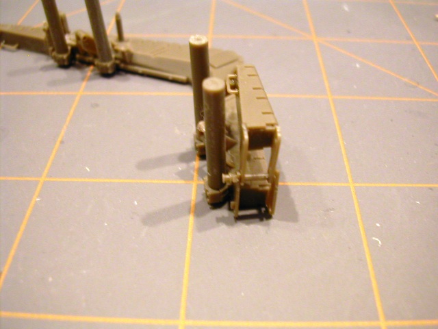
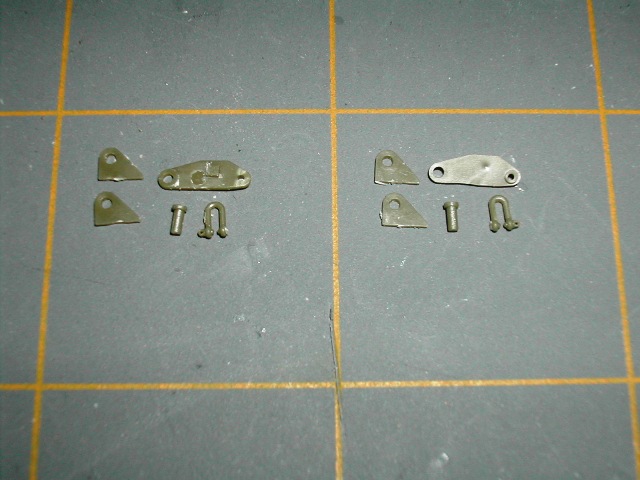
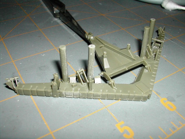
In sub-step 2, you are installing the bottom vertical supports(O44,O46 and O43,O45) for the 'engineer rack' on to the rack base (O38) that was assembled in sub-step 1. In this picture, I have installed O45 and O46 and am getting ready to install O43 and O44.
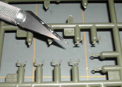
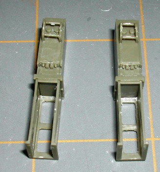
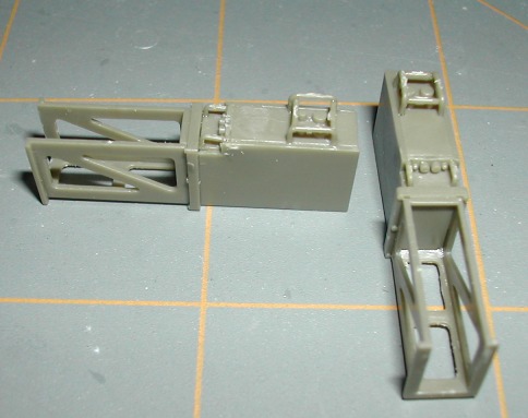
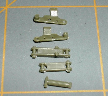
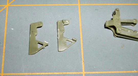
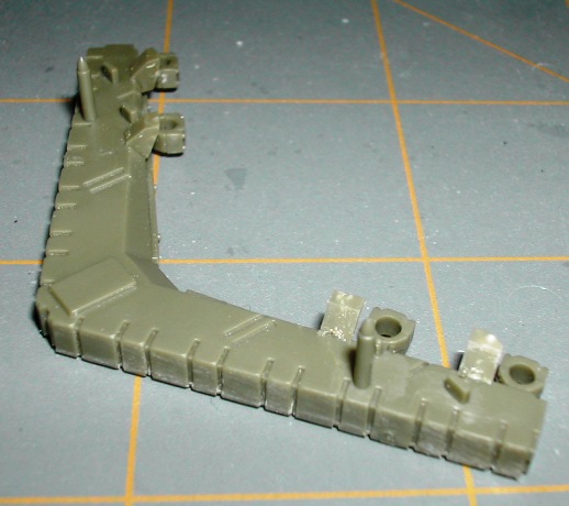
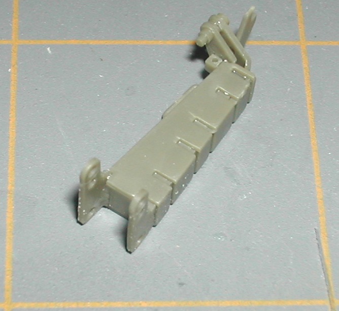
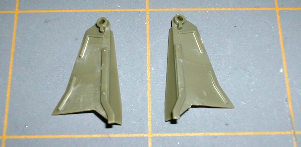
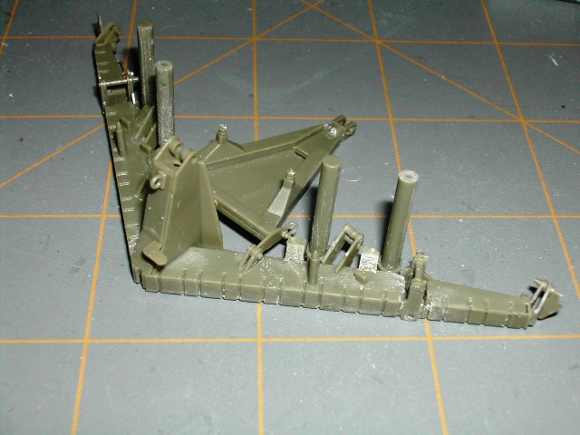
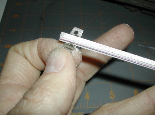
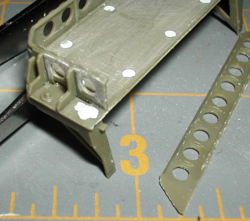
Sub-step 3 is the installation of the side rails of the 'engineer rack'. This sub-step required a lot of parts clean up as a result of the abundance of ejector pin marks. I had use a sanding stick to get between some of the part features on O40 and O41 as shown here.
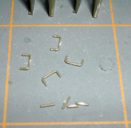
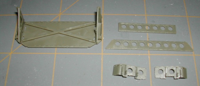
Here is the parts layout after clean up was completed.
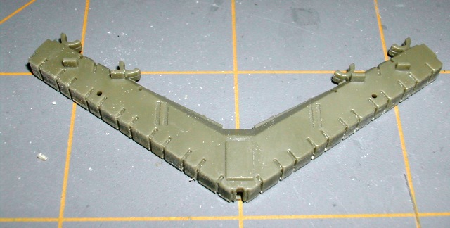
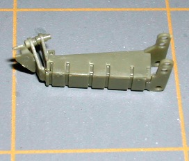
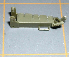
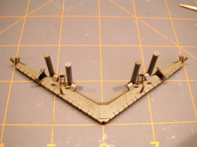
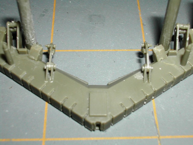
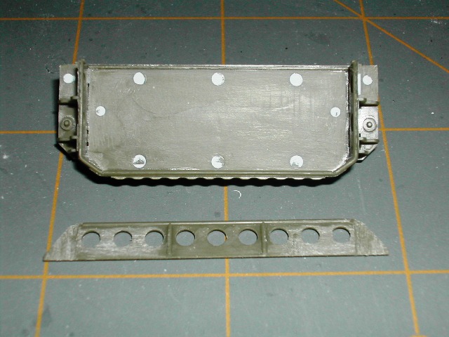
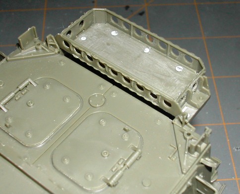
In this photo, I have the left and right side rails installed. Note the significant number of ejector pin marks visible in this picture of the base of the rack(O38).
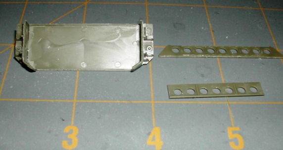
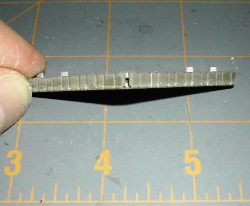
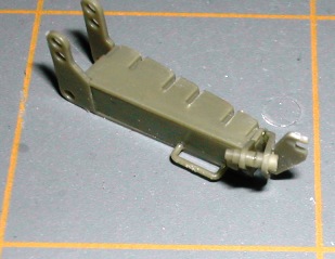
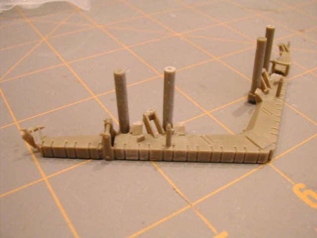
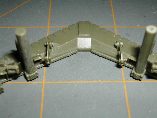
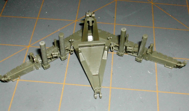
Here I have installed the rear rail of the rack and I've applied drops of Mr Surfacer 500 to the injector pin marks on O38 (rack base).
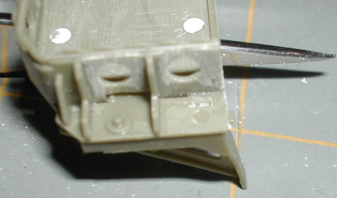
In the next two photo's, you can see the 'slots' where parts O45 and O46 fit into O38 and ejector pin marks. I filled these with Mr. Surfacer 500 also.
I let the Mr. Surfacer cure overnight. It is absolutely critical that you wait to put on the front rack rail or you will not have adequate access to the base of O38 to sand the ejector pin marks.
After the applications of Mr. Surfacer cured, I then sanded all areas using a combination of a dremel on low speed, an x-acto knife and a sanding stick section.
Apparently I did not take a picture of the completed assembly at the end of sub-step 3.

Sub-step 4 is the installation of the 'engineer rack' on the rear of the ESV.
There are not any definitive marks or any alignment pins to help you place the rack on the back of the ESV. So, I referenced the Ralph Zwilling Stryker book again and proceeded to do some analysis and test fitting. Here is how the rack is mounted/aligns in a photo in Ralph's book.
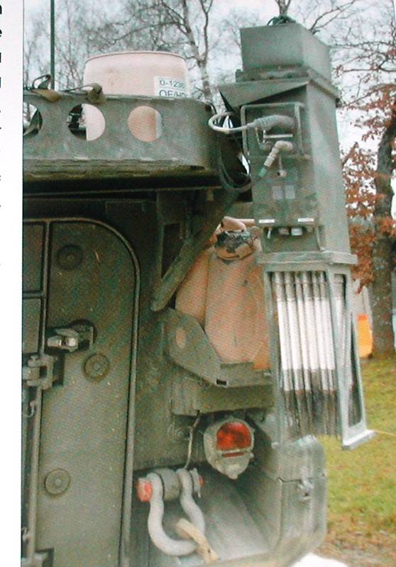
Note how the vertical support for the rack extends down to just above the jerry can rack vertical support. Note also how the engineer rack vertical support is is set just to the inside of the jerry can rack vertical support. This was the best frame of reference I could find so I proceeded with installation using this photo and a couple of other pictures for reference.
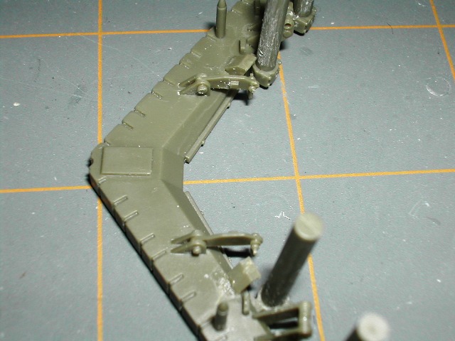
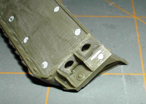
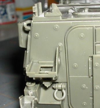
As I began additional test fitting based on the photo from the Stryker book, I identified that two applique armor boltheads on each side were going to prevent the engineer rack vertical support from mounting flush to the rear hull wall. Here is a picture showing how the two boltheads line up behind the rack vertical support.
Here is an unobstructed view of the interferring boltheads on both sides.
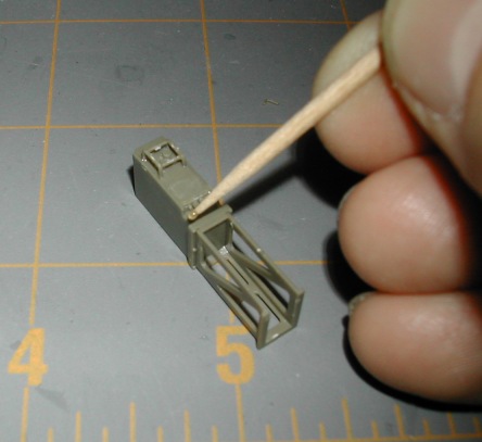
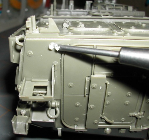
To get the engineer rack vertical supports to mount flush against the rear hull wall as shown in the photo, the four boltheads (two each side) must be removed. I accomplished this with a tool distributed by Mission Models called a 'Micro-Chisel'. This is a great tool and I highly recommend it for everyone's tool box. Here is an 'in-action' shot of the micro chisel.

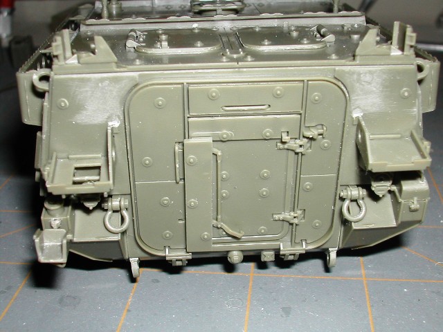
Here is an overall photo of the rear wall after the 4 boltheads were removed and the area lightly sanded down.
Here is a close-up of the right side after bolthead removal.
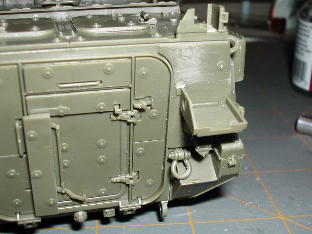
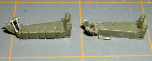
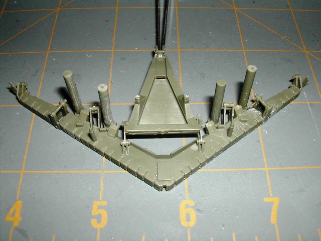
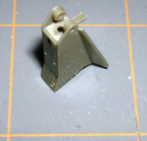
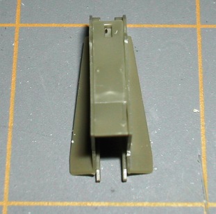
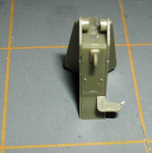
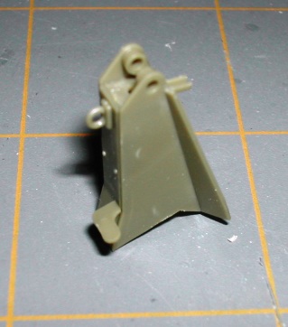
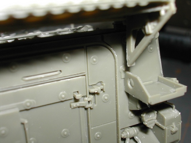
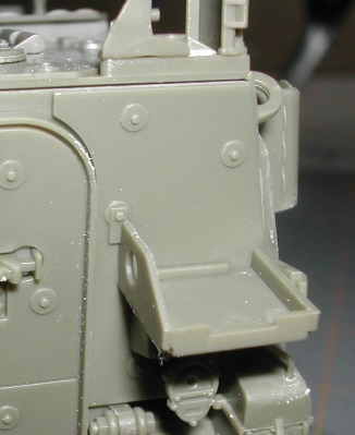
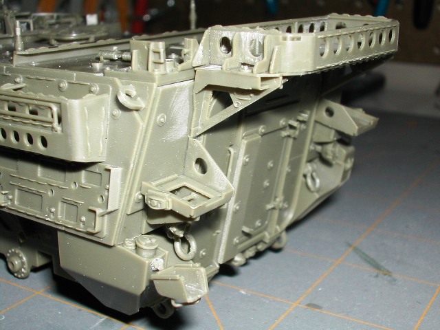
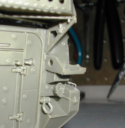
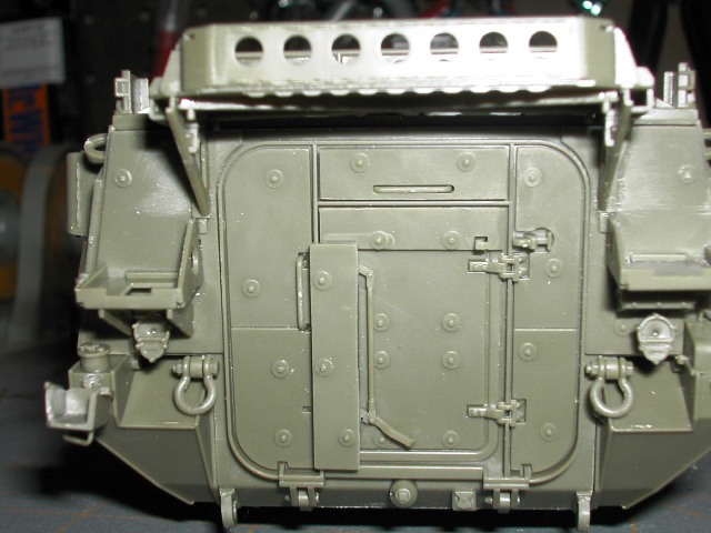
These last four photos show step 36 completed. Note the alignment of the engineer rack vertical supports (O45,O46) on the kit as compared to the book photo above. I don't think it came out to bad.
I feel that this rack, although it isn't a very exciting part, is a significant focal point for this model as a result of it being a large, unique feature of this vehicle. If you are building this kit out-of-box, this rack is empty when you are completed. As a result, it is critical you take the time to clear all ejector pin marks and ensure you do the best job possible with fitting your side rails together. Otherwise, the appearance of this feature will be sub-standard.