Armor/AFV: Modern - USA
Modern Armor, AFVs, and Support vehicles.
Hosted by Darren Baker
AFV Club M1132 Stryker ESV w/SMP
sgtsauer
#065
Visit this Community
Missouri, United States
Joined: March 30, 2002
KitMaker: 2,605 posts
Armorama: 1,814 posts
Posted: Sunday, December 05, 2010 - 05:09 PM UTC
STEP 24:

Step 24 is the construction and installation of the headlights (sub-assembly F)/drive marker lights(sub-assembly E) as well as installing the 'nose' of the vehicle part O29.


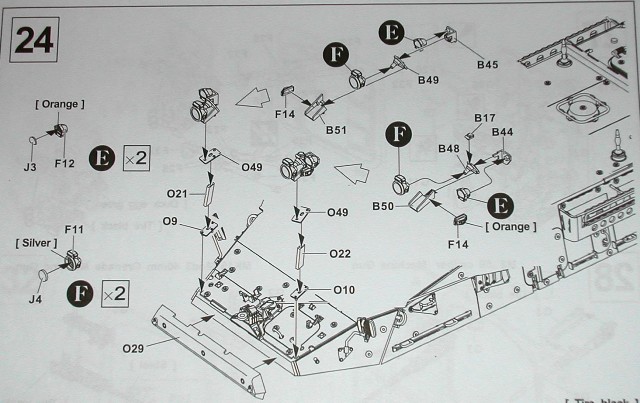
On this step, I did not install any of the clear parts. I will do that toward the end of finishing the kit after all of my final detail painting is completed. Part O29 was installed earlier in construction and is shown already in place in the step-by-step photos here.

My recommendation to you on this step is to install parts O9, O21 and O49 first. When you install those parts, let the glue cure for at least 24 hrs so that you have a solid assembly to work with when you install sub-assemblies E and F. I believe if you install sub-assemblies E and F to part O21/O49 prior to installing O9/O21/O49 on the hull, the off-set weight will be too heavy and you will have a hard time getting parts O21 and O22 to dry at the correct angle necessary.

Overall, I had a very difficult time with assembling the headlights and getting everything to assemble and dry at the correct angle.

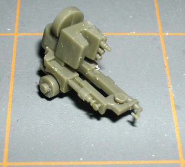
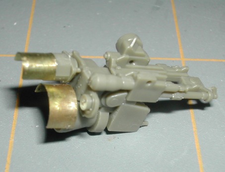
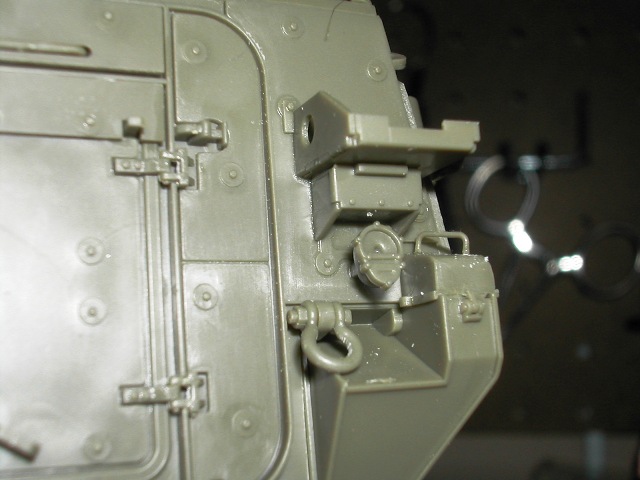
The first thing I did was assemble parts B51 and B49.


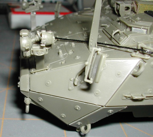
I then installed parts F11/F12 onto B49. This photo shows the very odd angle that parts F11/F12 need to sit at when assembled.


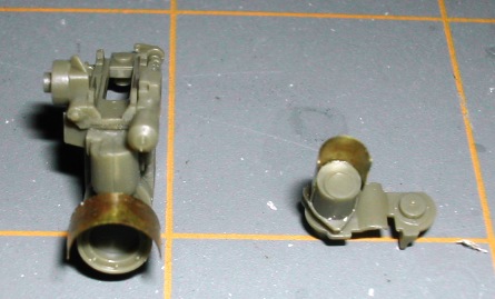
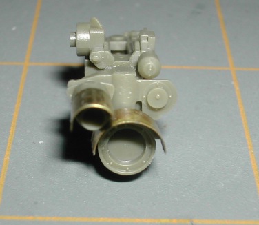
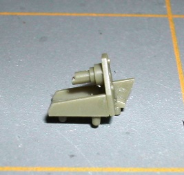
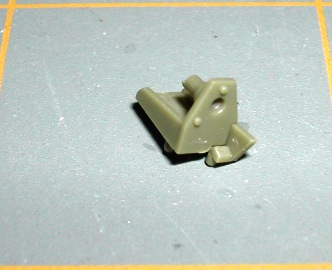
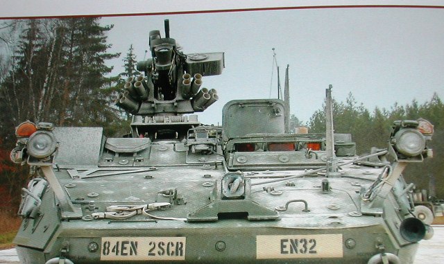
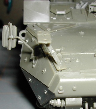
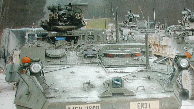
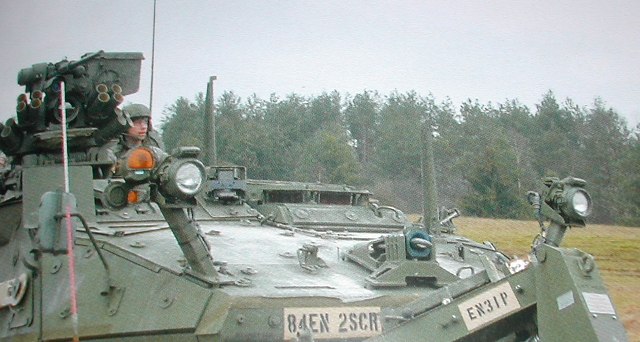
While the glue on the light assemblies cured, I installed O9, O21, O49 and O10, O22 and O49. Take note in the reference photos (again from Ralph Zwillings incredible book) of the angle that part O21 and O22 sit at.


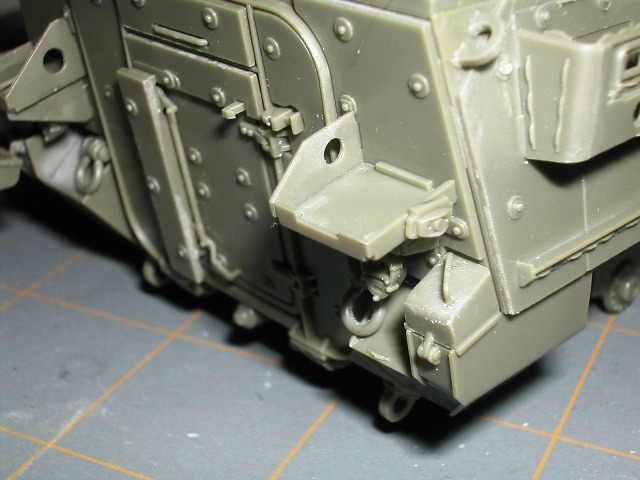
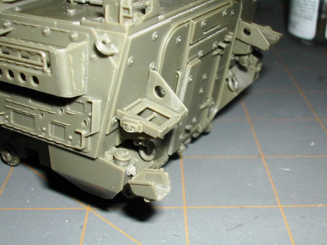
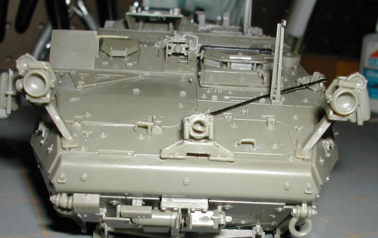
Here are a couple of shots of the installed O9, O21, O49 and O10, O22 and O49.


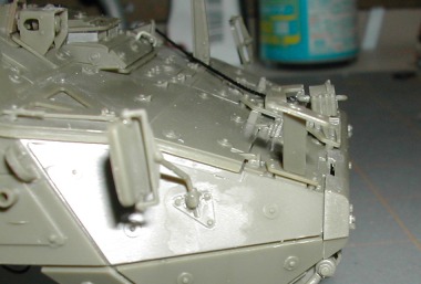
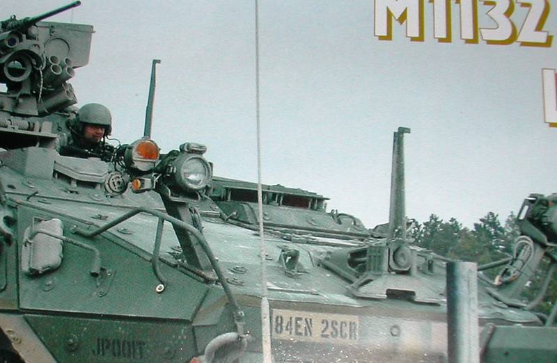
After 24 hours, I installed the headlight/drive light assemblies to parts O49. Here are a few more shots out of Ralphs book to reinforce the height and angles that these parts must sit at.


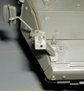
Here are a few final shots of the step 24 completed.


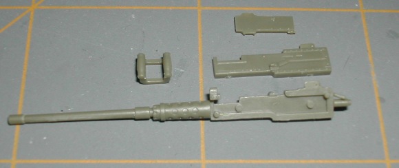
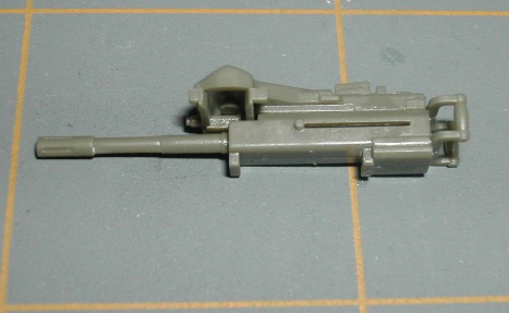
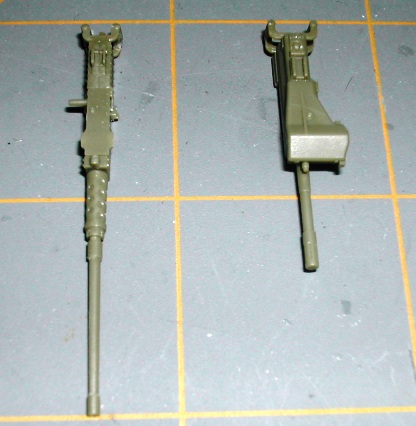
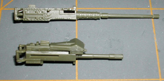
One point of interest is the appearance of kit part F14 as compared to how it looks on the real vehicle. AFV Club did a good job coming up with a 'compromise' part. I think the type of mounting bracket seen on the real vehicle could only be replicated in photo-etch.

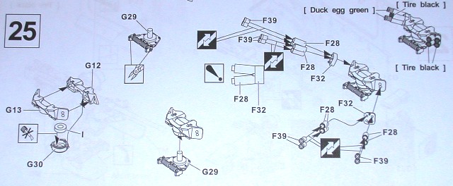
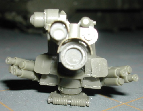
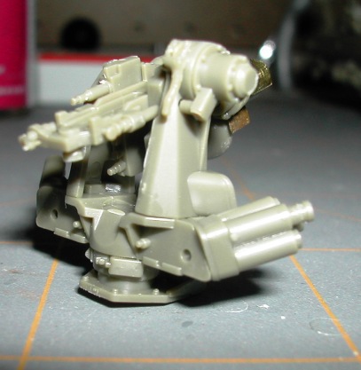
In step 25, I will begin construction of the RWS (Remote Weapon System). Stay tuned!
sgtsauer
#065
Visit this Community
Missouri, United States
Joined: March 30, 2002
KitMaker: 2,605 posts
Armorama: 1,814 posts
Posted: Friday, December 10, 2010 - 06:59 PM UTC
STEP 25:

Step 25 has you assembling the base for the M151 RWS (Remote Weapon System).


I followed the construction sequence from left to right and began assembly with G12, G13, G29 and G30.

There are two small nubs that have to be cut off of G29. The nub is to the left and right of the 'spring' on part G29.

Here is a picture of the G29 with the 'nubs' still on:


Here is part G29 with the 'nubs' removed:


Here are step-by-step shots of assembly of G12, G13, G29, and G30:


The challenge I had here is that part G30 split in half when I put the assembly (G12, G13, G30) onto part G29.

The remainder of this step is spent assembling the smoke dischargers. There was nothing out of the ordinary with the smoke discharger assemblies. One strange point is that the instructions show you putting 8 'caps' F39 on parts F28. The challenge with this is that the kit only has 4 ea of F39.

Installing parts F39 on parts F28 was a challenge because my fingers are so large and the parts are so small. The F39 parts are super small, smaller than the tip of an X-Acto blade. However, I prevailed without losing any parts.


Here is a picture of the assembled RWS base:


sgtsauer
#065
Visit this Community
Missouri, United States
Joined: March 30, 2002
KitMaker: 2,605 posts
Armorama: 1,814 posts
Posted: Saturday, December 11, 2010 - 07:43 AM UTC
STEP 26:

Step 26 has you constructing the weapon mount for the RWS.


Side view of part G20 after attaching G25.


G16 & G17 after assembly.


G16/17 assembly installed on G20 with G23 installed also.


Mount assembly with G21 installed.


The next two pictures show the mount assembly with part G18 installed. It also shows a sub-assembly consisting of parts G22 & G27. I'm preparing to bend PE parts M4 and M5 for installation. I assembled G22//G27 seperate from the main mount assembly to make installation of the sun shades/weather shields on both assemblies easier to install.


The next picture shows the PE parts M4/M5 next to their corresponding bending 'jigs' that are cast in the sprue of 'G'.


The concept is that you simply bend M4/M5 over the right 'jig' and then install on your mount assembly. However, this didn't work out well for me for a couple of reasons.
1. The brass is very hard and did not bend well.
2. I could not get enough force on such small PE parts to get complete bends across the entire jig surface.

So, to address the above issues I did two things.
1. I heated the PE parts over a candle which softened the brass and made it easier to bend.
2. I used a tool distributed by Mission Models called 'Multi-Tool Small' to bend the PE parts. Here is a couple of photos of the tool:


Using the tool enabled me to get a more complete bend in the PE parts. The fit of the PE parts was much better after using the tool.

Here is a picture of the main mount assembly and sub-assembly (G22,G27) after bending and installation of the PE parts.


The last three pictures here shows Step 26 completed. You are supposed to install clear part J5 on part G18 in this step but I will not install it until the final finishing steps. I might actually use an MV or Greif lense instead.


sgtsauer
#065
Visit this Community
Missouri, United States
Joined: March 30, 2002
KitMaker: 2,605 posts
Armorama: 1,814 posts
Posted: Saturday, December 11, 2010 - 11:50 AM UTC
STEP 26 CORRECTION:

In Step 26 above, the instructions show you putting the small sun/weather shield (M4) over the middle of part G27 as I had shown in this photo.


After looking closer at photos in the Stryker book again, it shows the shield all the way back to the base of part G27 as shown in the picture below.


So, it should look like this:
sgtsauer
#065
Visit this Community
Missouri, United States
Joined: March 30, 2002
KitMaker: 2,605 posts
Armorama: 1,814 posts
Posted: Saturday, December 11, 2010 - 12:13 PM UTC
STEP 27:

Step 27 continues the assembly of the RWS. In this step you are assembling the mount to the RWS base and adding two more sets of quad-barrel 66mm grenade launchers.


One point I want to make is that in Steps 25 and 27, you are given the option to use parts F39 to represent screening grenades. It gives you the option to use F39 sixteen times. However, there are only four in the kit. So make sure you put them where you want them because four is all you got.

Here are three shots after the first half of the step is complete.


Here are two photos of the RWS at the end of this step.


In step 28, I will be assembling the M2 .50 cal and the MK. 19 Mod 3 40mm Grenade Machine Gun........Stay tuned!!!


sgtsauer
#065
Visit this Community
Missouri, United States
Joined: March 30, 2002
KitMaker: 2,605 posts
Armorama: 1,814 posts
Posted: Saturday, December 11, 2010 - 06:31 PM UTC
STEP 28:

Step 28 is assembly of the RWS armament. You have two choices of weapons for the RWS.
1. M2 .50 cal Machine Gun
2. MK. 19 Mod. 3 40mm Grenade Machine Gun


There weren't any tricks or surprises in this step. Normally I would pick one weapon and only assemble that weapon. But, I thought some of you looking at this blog and contemplating a build might want to see both weapons assembled.

Here is a parts layout of the .50 cal (I forgot to do one for the MK. 19)


Here are both weapons assembled.


sgtsauer
#065
Visit this Community
Missouri, United States
Joined: March 30, 2002
KitMaker: 2,605 posts
Armorama: 1,814 posts
Posted: Saturday, December 11, 2010 - 06:42 PM UTC
STEP 29:

Here you assemble the ammunition container, mount the weapon you selected in Step 28, mount the ammunition container to the RWS mount and attached two PE chains M7/M8.


Here is a parts layout for the ammunition container.


Here is the ammunition container assembled.


Here is a photo of the PE chain installation.


Installing the PE chains is probably hardest thing I've attempted to do with PE, heck maybe in modelling altogether. It became very difficult to steady the RWS assembly and bend and position the PE chain where I needed to. So, I decided to cut step 29 short, mount the RWS on the vehicle hull and then finish the chain installation. I literally spent about 1-1/2 hours mounting the two PE chain parts.

See Step 30 for the complete RWS system mounted on the vehicle.
sgtsauer
#065
Visit this Community
Missouri, United States
Joined: March 30, 2002
KitMaker: 2,605 posts
Armorama: 1,814 posts
Posted: Saturday, December 11, 2010 - 06:50 PM UTC
STEP 30:

Step 30 consists of mounting the completed Remote Weapon System to the vehicle commanders station on the hull.


Here are four images of the complete RWS after mounting to the vehicle.


The RWS assembly overall wasn't too bad. I intend to build every variant of the Stryker that AFV Club releases. However, the PE chain installation sure is a deterrent to that concept.
seb43
Visit this Community
Paris, France
Joined: August 30, 2005
KitMaker: 2,315 posts
Armorama: 2,158 posts
Posted: Saturday, December 11, 2010 - 09:04 PM UTC
And Now the blade right ????
Cheers
Seb
Burik
Visit this Community
New Jersey, United States
Joined: March 12, 2002
KitMaker: 1,437 posts
Armorama: 1,303 posts
Posted: Sunday, December 12, 2010 - 02:36 AM UTC
Hi Brent, this is really great stuff. I figured now that you have covered the RWS I would provide these interior shots of the ammo can in case anyone ever wanted to depict it open. As you can see, there is an adjustment to the interior depending which ammunition one is using.


Also, for those who are detailing the RWS, keep in mind that the kit is missing the black spent shell chute, and the spent shell bag(s) - front and rear. For the super detailers there are some large wires as well along the sides and front of the rws. I highly recommend the WWP books for this.

Bob
KoSprueOne
Visit this Community
Myanmar
Joined: March 05, 2004
KitMaker: 4,011 posts
Armorama: 1,498 posts
Posted: Sunday, December 12, 2010 - 04:08 AM UTC
Burik, whoa cool and very helpful detail shots.

sgtsauer, I'm most impressed by your step-by-step layout. Very clear and detailed. I also have this kit but have not started yet, but I'm watching this to help me with mine later


Quoted Text

by seb43
And Now the blade right ????
Cheers
Seb


Hahaha !


retiredyank
Visit this Community
Arkansas, United States
Joined: June 29, 2009
KitMaker: 11,610 posts
Armorama: 7,843 posts
Posted: Sunday, December 12, 2010 - 04:26 AM UTC
Very nice build, so far Brent. I've been considering adding one of these to my stash since they came. Your build has convinced me to get one for Christmas.
seb43
Visit this Community
Paris, France
Joined: August 30, 2005
KitMaker: 2,315 posts
Armorama: 2,158 posts
Posted: Sunday, December 12, 2010 - 05:26 AM UTC

Quoted Text

Burik, whoa cool and very helpful detail shots.

sgtsauer, I'm most impressed by your step-by-step layout. Very clear and detailed. I also have this kit but have not started yet, but I'm watching this to help me with mine later


Quoted Text

by seb43
And Now the blade right ????
Cheers
Seb


Hahaha !


Brent
because so fare it is an ICV build
sgtsauer
#065
Visit this Community
Missouri, United States
Joined: March 30, 2002
KitMaker: 2,605 posts
Armorama: 1,814 posts
Posted: Sunday, December 12, 2010 - 06:40 AM UTC
@ Burick- Great pictures....It would be neat to display the ammunition container open with some of those fancy .50 brass rounds/photo-etch links. I certainly am not going to do it on this build. SOmeone needs to come out with a quality 40mm GMG ammunition belt to display on these things.

I have an AFV M1128 MGS that I'm going to super detail with a Voyager set. I may consider using the brass rounds/pe links on that kit. I'll be asking you for some opinions/guidance on that project...I kind of consider you the Stryker 'Godfather'.

@KoSprueOne- Thanks for the compliments..Its been a lot of fun so far.

@Retiredyank- Despite some of the nitpicking of the kit that I've done, its a great kit and I highly recommend it.

@Seb- The wait is killing you isn't it... Patience....I'm almost there. Now back to working in the 'ICV'. LoL
Burik
Visit this Community
New Jersey, United States
Joined: March 12, 2002
KitMaker: 1,437 posts
Armorama: 1,303 posts
Posted: Sunday, December 12, 2010 - 08:01 AM UTC

Quoted Text

@ Burick- Great pictures....It would be neat to display the ammunition container open with some of those fancy .50 brass rounds/photo-etch links. I certainly am not going to do it on this build. SOmeone needs to come out with a quality 40mm GMG ammunition belt to display on these things.

I have an AFV M1128 MGS that I'm going to super detail with a Voyager set. I may consider using the brass rounds/pe links on that kit. I'll be asking you for some opinions/guidance on that project...I kind of consider you the Stryker 'Godfather'.


Ha, ha. I need to push on w/ my two Strykers w/ slat I am doing right now. God, how I hate that slat. I too will be doing most of the other variants but without slat. I really love the look of the early Strykers at the NTC with all the gear they carried, and the MILES stuff too. I will be doing the Canadian LAVIII too. That thing is cool w/ the turret they have - and no slat when deployed!

Anyway, looking forward to more progress on this baby. The plow really makes this variant look mean.
sgtsauer
#065
Visit this Community
Missouri, United States
Joined: March 30, 2002
KitMaker: 2,605 posts
Armorama: 1,814 posts
Posted: Friday, December 17, 2010 - 07:47 AM UTC
STEP 31:

In this step, you are doing the construction of the rear troop ramp/door.


There were not any surprises or problems encountered during this step. Assembly was pretty straight forward.


In the picture just below, you are assembling an interior component to the inside of the troop ramp. Although I will not have the rear troop ramp/door open, I thought I would go ahead and assemble it so the you can see what it looks like assembled. This may be valuable to someone thinking about doing an interior.


Photo of the interior of the assembled troop ramp/door.


Exterior view of the completed assembly.


Step 32 begins rear hull construction.
sgtsauer
#065
Visit this Community
Missouri, United States
Joined: March 30, 2002
KitMaker: 2,605 posts
Armorama: 1,814 posts
Posted: Friday, December 17, 2010 - 08:08 AM UTC
STEP 32:

Step 32 is very short. It consists of assembling 5 parts (rear hull, 2 tie down points, 2 ramp hinge points) and the rear troop ramp/door. The step consists of two sub-steps.


The first sub-step gives you the option of installing a towing pintle. From the photos and books that I've looked at, I did not see an ESV with the tow pintle installed. So, I am not installing it on this kit build.

The second sub-step has you installing the the two tie-down points (F30), the two ramp hing points(E15) and the rear ramp assembly on the rear hull piece (P16).


When I installed the rear troop ramp/door assembly into the rear hull wall, I could not get it to sit 'flat' in the opening. So, I applied a lot of liquid cement, used a couple of small clamps to apply constant pressure and let the assembly sit so the glue would set.


Here is Step 32 completed.


Coming up in Step 33 is installation of the rear hull wall, rear recovery shackles and assembly of the rear fender fuel tank filler access and covers.

sgtsauer
#065
Visit this Community
Missouri, United States
Joined: March 30, 2002
KitMaker: 2,605 posts
Armorama: 1,814 posts
Posted: Friday, December 17, 2010 - 09:37 AM UTC
STEP 33:

In Step 33, you are installing the rear hull wall, 2 tow shackles(F29), 2 fuel filler caps(P50), 2 unknown parts (P51), 2 fuel filler covers (B25) and 2 handles (F17).


There weren't any problems on this step. Your one challenge is cleaning up parts F17, P50 and P51 due to their very small size. Be patient and use a fresh, sharp x-acto blade and you should be ok.

Here is a picture showing the rear hull wall installed.


Here is a shot of the parts that get installed next.


I opted to show one fuel filler cover closed (right side) and have one fuel filler cover open (left side).

Here is Step 33 completed.


The instructions conveniently contain two photographs from Ralph Zwillings Stryker books. I used the photos on the instruction sheet and the additional photos in the books as a guide for placement of parts P50, P51 and the angle of the fuel filler cover (B25).
seb43
Visit this Community
Paris, France
Joined: August 30, 2005
KitMaker: 2,315 posts
Armorama: 2,158 posts
Posted: Friday, December 17, 2010 - 07:40 PM UTC
Nice touch regarding the fuel cap
cheers
Seb

Burik
Visit this Community
New Jersey, United States
Joined: March 12, 2002
KitMaker: 1,437 posts
Armorama: 1,303 posts
Posted: Saturday, December 18, 2010 - 01:02 AM UTC
Brent, let me know if I am getting in the way. Don't plan on posting too much. When I saw your open fuel cover I thought of this:

Here is a photo for detailers that might be helpful. This shows the plug-ins for the slave cables for towing a vehicle. They are not on the kit.


retiredyank
Visit this Community
Arkansas, United States
Joined: June 29, 2009
KitMaker: 11,610 posts
Armorama: 7,843 posts
Posted: Saturday, December 18, 2010 - 01:25 AM UTC
Seems to be progressing nicely Brent. I'm hoping I will get one of these for Xmas. Definitely use your build thread to do mine.
sgtsauer
#065
Visit this Community
Missouri, United States
Joined: March 30, 2002
KitMaker: 2,605 posts
Armorama: 1,814 posts
Posted: Saturday, December 18, 2010 - 04:51 AM UTC
@ Burik- I intended for this project/posting to be a resource to other model builders. Your posts are very welcomed and encouraged here. Your knowledge and content contributions increase the value of this project and make it more comprehensive for others. So, please feel free to contribute here.
sgtsauer
#065
Visit this Community
Missouri, United States
Joined: March 30, 2002
KitMaker: 2,605 posts
Armorama: 1,814 posts
Posted: Monday, December 20, 2010 - 03:03 AM UTC
STEP 34:

Step 34 has you assembling the 5 gallon water cans, 5 gallon fuel cans and installing the lenses in the rear lights.


I will not install the lenses in the rear lights until the final steps of the project.

AFV Club has done a great job capturing and recreating the difference in details between the US water can and fuel cans. I regretfully did not take any pictures of the water can parts prior to assembly.

Here is a photo of the fuel can parts minus the center handle section before assembly.


Your challenge in this step is to remove the mold release point from the top of fuel can cap. Here is a picture of the fuel can cap BEFORE removing the mold release point.


Here is a picture (not as clear) of the fuel can cap after removal of the mold release point.


If you look closely, you will notice that the fuel can cap has a kind of jagged pattern around its edge. That is extremely difficult to recreate on the cap section that had the mold release point.

Here is the two fuel cans and two water cans after assembly. I will do some additional sanding and clean up toward the end of the project prior to painting.


sgtsauer
#065
Visit this Community
Missouri, United States
Joined: March 30, 2002
KitMaker: 2,605 posts
Armorama: 1,814 posts
Posted: Monday, December 20, 2010 - 09:28 AM UTC
STEP 35:

Step 35 has you installing the rear lights, assembling the jerry can racks and installing the jerry can racks.


The model builder has two configurations of jerry can racks to choose from. Each of the two configurations have multiple part differences. So, you have to ensure you use all the correct parts for your chosen configuration. The easiest parts to reference in photographs is the inside edge vertical supports (D36, D37 with hole or P5, P9 no hole). After looking at several photographs, all ESV’s seem to have the jerry can rack vertical supports that have the hole in them (D36, D37) so those are the parts/configuration I chose to use.

The assembly of the right side jerry can rack is straight forward and there were no issues.


The left side jerry can rack assembly is a little trickier. Here is a layout of the parts.


For the left side assembly you have to put a 'rod' (D32) between D31 and D39 while installing D31/D39 below D35. If you look on D31 and D39 you can see a 'raised' circle on each part. Those are placement guides for D32.

To complete this part of the assembly, I installed parts D35 and D37 onto the rear hull wall first using liquid glue. After the glue had a few minutes to set, I installed parts D31 and D39 using liquid glue. I let it set for a few minutes to 'stiffen' in place a bit. Once D31 and D39 were somewhat difficult to move left or right in place, I put CA on both ends of D32. I then took D32 and aligned it with the 'raised' circle that is on the inside edge of D31/D39. I used a pair of tweezers to apply pressure from both sides to seat D32 in place. I then used a drop of accelerator on both sides of D32 to set the CA in place. At this time, I did my final alignment of D31, D32, D39 with D35 and glued the top of D31 and D39 to the bottom of D35 using liqued glue.

After all parts had enough time to set, I glued F14 on both the right and left jerry can rack frames. Based on photographs, F14 needs to be glued in place parallel with the ground and not the rack itself.

Here are a few pictures of the completed left side rack.


Notice in this view how part D32 sits inside of the 'raised' circle on the inside of D39.
Nito74
Visit this Community
Lisboa, Portugal
Joined: March 04, 2008
KitMaker: 5,386 posts
Armorama: 4,727 posts
Posted: Monday, December 20, 2010 - 01:40 PM UTC
Great blog on the 1132 !!!

Amazing detail, and careful step by step build .
I was planning to get one but the only version available was the Trumpeter with a blade and a different mine roller system.

I'm also planning to build this version from AFV since it has a different MR system, anyway I got some Trumpeter versions and AFV's.

I'll keep both eyes on this one !!

Since I'm moving away from my house most of my kits are packed and I'm not sure when I'll be able to build those Strykers. I'll just drool over every Armorama build log...