

I forgot to mention , and forgot to add to my model that I have seen reference pics of the Fitters vehicles with some of the water jerries in the racks upside down. I assume this denotes an empty water jerry. would of been a nice detail to add to the kit to have a couple upside down... Too late for me but for someone else maybe this could work!
Adam
Hosted by Darren Baker
ASLAV F (Fitters) Build log, Iraq 2006
Adamskii

Joined: November 06, 2010
KitMaker: 537 posts
Armorama: 474 posts

Posted: Wednesday, December 29, 2010 - 12:48 AM UTC

jasmils
Joined: December 23, 2003
KitMaker: 1,016 posts
Armorama: 745 posts

Posted: Wednesday, December 29, 2010 - 02:12 PM UTC
Instructions rectified.
Cheers Jason

Anirudharun

Joined: February 16, 2008
KitMaker: 597 posts
Armorama: 530 posts
Posted: Wednesday, December 29, 2010 - 10:55 PM UTC
Awesome build Adam, this is really informative and useful. The ASLAV looks very nice so far.
That looks to be a huge dio your building, I cant wait to see it finished.
That looks to be a huge dio your building, I cant wait to see it finished.
Adamskii
Joined: November 06, 2010
KitMaker: 537 posts
Armorama: 474 posts
Posted: Thursday, December 30, 2010 - 12:47 AM UTC
Thankyou for your comments - just the thing I need to keep me motivated to carry on!
I must say I would rather try build a squadron of ASLAV's than scratchbuild a single interior! talk about giving yourself a challenge!
Thanks again,
Adam
I must say I would rather try build a squadron of ASLAV's than scratchbuild a single interior! talk about giving yourself a challenge!
Thanks again,
Adam
Adamskii
Joined: November 06, 2010
KitMaker: 537 posts
Armorama: 474 posts
Posted: Thursday, December 30, 2010 - 03:27 AM UTC
The Crane.
This is the bit I think I will cover in detail the most. The kits instructions are basically a series of photos of the completed assemblies, with the parts listed. I will try and put the construction in a sequence, and include the parts (if added during a step) so combine the two.
first off - heads up - I was given some good advice not to glue the working assemblies until the very very end. There may be an issue with alignment /twisting of the jib to the mast assembley. so be carefull and only glue what obviously is not a moving pin or hinge (unless necessary).
First i like to replace hydraulic Rams with aluminium rod where possible. If I built this crane again, I would of added alot more too!
So before starting the first step I switched some parts to aluminium tube.

the first assembly is basically a collection of parts. Build parts as shown. Ther is obviously a need to build in sequence as once glued you can't pry them open to install a hinged rod or something. do not glue parts E24 and E40 at this stage. E19 should float freely. The main base parts E5 and E6 can be glued together with E19 free to move.

I secure the back of E24 and E40 with tamiya tape.

At this point the rams smaller inserts are lined up with the parts they will mate too.

First do part E3 into FA2 (once FA2 is in place it would not be easy to fit E3 without breaking seams) E3 fits onto E28

now I fit part FA2 ino the main arm, making sure the two hinged pins mate when joining the two sides. That tamiya tape is helping alot about now!

check for alignment

The JIB
the jib assembly is quite simple but some clean up is needed see the white squadron putty in the ejector pin holes from the sprue.

caefull attention to the smaller parts here - also I cut off the small cubed block on top of the jib head. reference pics dont show this to exist.

dont glue the jib into it holder, let it slide freely. Insert a 0.5mm rod into the jib holder, and secure it to the jib head (part FA3). this represents the ram that would travel the jib in and out.

I then attach the jib and holder to the rest of the crane body, checking for square and especially twisting


now I am happy the main parts are workable / moveable, and nothing else to be fitted withing the body of the crane, I can glue the main assembly together - I remove the tamiya tape and secure. I see some gap in the seam so immeadiately fill with squadron white putty, and leave to dry overnight. I also fill the mating holes of the FA1 as they do not align with the crane and are not easily fixed.

The next day I sand back the putty, and start adding the plumbing fixtures.

more plumbing fixtures added and some side detail , part FA7. The plumbing clamps are quite clever and can be used as intended.

the small stuff - the "Pirtek" fittings on FA1 are tiny and alignment is important.

I install the "Pirtek" hose fittings to the crane frame - these mark the joins between different types of hydraulic line

I add some of the fixed bunting lines with 0.5mm white plastic rod. they feed straight throught the clamps. I use longer hoses than needed, then trim in place to exact length needed to match the fitings. Also, cut the two mating plugs from the bottom of the crane (we filled the matching plugs in FA1)

glue the bottom of the crane in place to FA1 - its a butt joint so no real strength, but at least you can align it centrally. Fit it over where the filled plugs went as a guide to where it should be. I also add some more rod to the jib.

I add the first two lines - these are using the solder supplied in the kit, and I cut each to 35mm which was quite adequate. I started by glueing to the holes in the crane body, and feeding solder back through the clamps until looping onto the correct fitting for each side , in this case the bent ones (FC3)

same again but with the solder that has the resin cover (FC5)- very clever ths, looks real authentic, I stripped about 5mm of the resin back from the joins on top the crane. then feed back along its patch to the final Pirtek fittings(FC2)

do this for both resin covered lines

Now i do some plastic rod work on the jib ram. Bending and prefitting is order of the day, it is fiddly. use the 0.5mm rod supplied in the kit. Iuse the same method as for making handles, where I bend around the tweezer shaft.

I add some of the solder to the main elbow in the crane, tucking it under the pin and out through the gap provided. be sparing with the solder as it just enough to do the kit.

I add the last lot of solder to the right side of the crane, and some plastic rod as described in the instructions. It is hard to get a clear photo of the underside of the crane here, and the pics I do have, have some conflicting examples of how it should look. In the end I just replicated what the instructions said as best as I could. Also I started adding bolt heads/ pins as I see them in reference pics. I use the bolt heads supplid (parts CY1)

I add some more bolts to superdetail the crane. also the crane head has a big pin/bolt through it so I added a 1.5mm diameter rod pin.

Some reference pictures show a metal eyelet on the back of the crane - So I added that with the spare solder.

The securing blocks
these are critical to the mounting of the crane - and test fitting again is order of the day. Rather than glue them to the deck and hope it all lines up, I do the reverse. I complete the assembly, and glue to the underside of the jib holder. see where I am going with this?
Important - the printed instructions do not show the location of any of these parts. The correction sent by email does not address the missing part FA5. there are 2 parts FA5, and they both are fitted, the most rearward one is hidden as it is locked into part FA8, with pin FA4 joining them. the other part FA5 sits behind the bump stop.

next I test fit everything - remember all my pivots still work - and the rams move so can pose the crane (except the jib) or move it around to best fit.

once happy with the location I glue the base in first, keeping that as square as I can.

the back end now floats freely and I can move it slightly to left and right to get it into perfect position


once happy with alignment - glue in place. A word on the crane - the jib is offset so dont center align the jib lock or the crane will look like its off by about 15 degrees, instead the jib looks like it lines up with the seam where the two rear doors meet, I used that as my center linde for the jib lock.

All done for the crane!


If you dont have the PDF instructions I suggest you get them from ACM. They are revised and have images and steps not in the printed version.
The crane because of its multiple number of joins and bends, by nature can twist and lean unless carefully checked after every step for alignment. ONly glue when absolutely certain something fits.
That was alot of work.
This is the bit I think I will cover in detail the most. The kits instructions are basically a series of photos of the completed assemblies, with the parts listed. I will try and put the construction in a sequence, and include the parts (if added during a step) so combine the two.
first off - heads up - I was given some good advice not to glue the working assemblies until the very very end. There may be an issue with alignment /twisting of the jib to the mast assembley. so be carefull and only glue what obviously is not a moving pin or hinge (unless necessary).
First i like to replace hydraulic Rams with aluminium rod where possible. If I built this crane again, I would of added alot more too!
So before starting the first step I switched some parts to aluminium tube.
the first assembly is basically a collection of parts. Build parts as shown. Ther is obviously a need to build in sequence as once glued you can't pry them open to install a hinged rod or something. do not glue parts E24 and E40 at this stage. E19 should float freely. The main base parts E5 and E6 can be glued together with E19 free to move.
I secure the back of E24 and E40 with tamiya tape.
At this point the rams smaller inserts are lined up with the parts they will mate too.
First do part E3 into FA2 (once FA2 is in place it would not be easy to fit E3 without breaking seams) E3 fits onto E28
now I fit part FA2 ino the main arm, making sure the two hinged pins mate when joining the two sides. That tamiya tape is helping alot about now!
check for alignment
The JIB
the jib assembly is quite simple but some clean up is needed see the white squadron putty in the ejector pin holes from the sprue.
caefull attention to the smaller parts here - also I cut off the small cubed block on top of the jib head. reference pics dont show this to exist.
dont glue the jib into it holder, let it slide freely. Insert a 0.5mm rod into the jib holder, and secure it to the jib head (part FA3). this represents the ram that would travel the jib in and out.
I then attach the jib and holder to the rest of the crane body, checking for square and especially twisting
now I am happy the main parts are workable / moveable, and nothing else to be fitted withing the body of the crane, I can glue the main assembly together - I remove the tamiya tape and secure. I see some gap in the seam so immeadiately fill with squadron white putty, and leave to dry overnight. I also fill the mating holes of the FA1 as they do not align with the crane and are not easily fixed.
The next day I sand back the putty, and start adding the plumbing fixtures.
more plumbing fixtures added and some side detail , part FA7. The plumbing clamps are quite clever and can be used as intended.
the small stuff - the "Pirtek" fittings on FA1 are tiny and alignment is important.
I install the "Pirtek" hose fittings to the crane frame - these mark the joins between different types of hydraulic line
I add some of the fixed bunting lines with 0.5mm white plastic rod. they feed straight throught the clamps. I use longer hoses than needed, then trim in place to exact length needed to match the fitings. Also, cut the two mating plugs from the bottom of the crane (we filled the matching plugs in FA1)
glue the bottom of the crane in place to FA1 - its a butt joint so no real strength, but at least you can align it centrally. Fit it over where the filled plugs went as a guide to where it should be. I also add some more rod to the jib.
I add the first two lines - these are using the solder supplied in the kit, and I cut each to 35mm which was quite adequate. I started by glueing to the holes in the crane body, and feeding solder back through the clamps until looping onto the correct fitting for each side , in this case the bent ones (FC3)
same again but with the solder that has the resin cover (FC5)- very clever ths, looks real authentic, I stripped about 5mm of the resin back from the joins on top the crane. then feed back along its patch to the final Pirtek fittings(FC2)
do this for both resin covered lines
Now i do some plastic rod work on the jib ram. Bending and prefitting is order of the day, it is fiddly. use the 0.5mm rod supplied in the kit. Iuse the same method as for making handles, where I bend around the tweezer shaft.
I add some of the solder to the main elbow in the crane, tucking it under the pin and out through the gap provided. be sparing with the solder as it just enough to do the kit.
I add the last lot of solder to the right side of the crane, and some plastic rod as described in the instructions. It is hard to get a clear photo of the underside of the crane here, and the pics I do have, have some conflicting examples of how it should look. In the end I just replicated what the instructions said as best as I could. Also I started adding bolt heads/ pins as I see them in reference pics. I use the bolt heads supplid (parts CY1)
I add some more bolts to superdetail the crane. also the crane head has a big pin/bolt through it so I added a 1.5mm diameter rod pin.
Some reference pictures show a metal eyelet on the back of the crane - So I added that with the spare solder.
The securing blocks
these are critical to the mounting of the crane - and test fitting again is order of the day. Rather than glue them to the deck and hope it all lines up, I do the reverse. I complete the assembly, and glue to the underside of the jib holder. see where I am going with this?
Important - the printed instructions do not show the location of any of these parts. The correction sent by email does not address the missing part FA5. there are 2 parts FA5, and they both are fitted, the most rearward one is hidden as it is locked into part FA8, with pin FA4 joining them. the other part FA5 sits behind the bump stop.
next I test fit everything - remember all my pivots still work - and the rams move so can pose the crane (except the jib) or move it around to best fit.
once happy with the location I glue the base in first, keeping that as square as I can.
the back end now floats freely and I can move it slightly to left and right to get it into perfect position
once happy with alignment - glue in place. A word on the crane - the jib is offset so dont center align the jib lock or the crane will look like its off by about 15 degrees, instead the jib looks like it lines up with the seam where the two rear doors meet, I used that as my center linde for the jib lock.
All done for the crane!
If you dont have the PDF instructions I suggest you get them from ACM. They are revised and have images and steps not in the printed version.
The crane because of its multiple number of joins and bends, by nature can twist and lean unless carefully checked after every step for alignment. ONly glue when absolutely certain something fits.
That was alot of work.
Austmouse
Joined: February 11, 2008
KitMaker: 104 posts
Armorama: 98 posts
Posted: Thursday, December 30, 2010 - 08:29 AM UTC
Great build Adam
A couple of points:
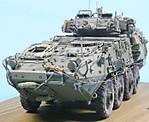
The commanders machine gun mount because of the way it has been designed - the machine gun can be moved around on its rail in the kit just like the rteal thing. The mount is a big improvement over the kit parts and can be purchased seperatley as MA126.
It appears that you have glued the crane in the stowed position. The concept behind the extra parts was trying to generate the full range of movement in the kit crane just like the real thiing. IF you are trying to do this you will also need to scoop out some plastic at the top of the bit that fits into the rotating base as otherwise the kit part impedes the main piston from have a full range of movement.
Our instructions are always being upgraded as customers bring points to our attention
Build on McDuff!!!
John M
John M
A couple of points:
The commanders machine gun mount because of the way it has been designed - the machine gun can be moved around on its rail in the kit just like the rteal thing. The mount is a big improvement over the kit parts and can be purchased seperatley as MA126.
It appears that you have glued the crane in the stowed position. The concept behind the extra parts was trying to generate the full range of movement in the kit crane just like the real thiing. IF you are trying to do this you will also need to scoop out some plastic at the top of the bit that fits into the rotating base as otherwise the kit part impedes the main piston from have a full range of movement.
Our instructions are always being upgraded as customers bring points to our attention
Build on McDuff!!!
John M
John M
Adamskii
Joined: November 06, 2010
KitMaker: 537 posts
Armorama: 474 posts
Posted: Thursday, December 30, 2010 - 02:40 PM UTC
Quoted Text
It appears that you have glued the crane in the stowed position. The concept behind the extra parts was trying to generate the full range of movement in the kit crane just like the real thiing. IF you are trying to do this you will also need to scoop out some plastic at the top of the bit that fits into the rotating base as otherwise the kit part impedes the main piston from have a full range of movement.
Our instructions are always being upgraded as customers bring points to our attention
Thanks for the comments John. As you rightly pointed out I have shown it in the stowed position. It is very much appreciated to have the option of stowed or in action. Other changes required if showing it in action is the need to put blanking plates on the underside of the crane as it is not supposed to be visibly hollow (when stowed this area in not able to be seen). But the crane could be put into almost any position with test fitting and minor modification. Someone make a kit of the lav engine and who knows what dioramas could be done (camp Smitty engine changeover? - nice) What else might the crane be used for ? what other things could it lift? I would love to do the fitters towing a disabled lav with that fantastic A frame.
I am unconvinced the Jib head is accurate - I have some photos of it looking quite different, but nothing clear or conclusive. There might be several variants or mods to the HIAB crane. Once I have more research I will fall to one side of the fence. Also theside of the crane should have 2 plates with "HIAB" embossed in them but I dont think I could pull it off to do that mod.
The instructions are updated phenomenally fast - I mentioned to Jason on Wednesday afternoon a few things I had found, and by Thursday morning he had sent a new PDF with the updates. Full credit for such immeadiate action to the makers of this resin kit. No other company provides service like this and certainly raises the bar for customer service to whole other level.
Nearly done on construction, just headlight assembly , prop guards, and some minor stuff I have missed along the way to add.
Adam
jasmils
Joined: December 23, 2003
KitMaker: 1,016 posts
Armorama: 745 posts
Posted: Thursday, December 30, 2010 - 09:22 PM UTC
G'day Adam,
To tell you the truth, I was aware of the problems with the crane, but after doing so much work to the rest of the kit, John and I made an executive decision not to redo the rest of the crane. For two reasons, one, the price of the kit was at a high enough price as it was and two, unless the modeller wanted to position the crane at its full hight, you would not really see the problems with it. As for the "HIAB" on the inside of the crane (or outside) none of the cars I climbed around have this plate. The HIAB used on the M113 Fitter has it, but not this version as far as I have seen.
Cheers Jason
PS Happy New Year.

Plasticbattle

#003

Joined: May 14, 2002
KitMaker: 9,763 posts
Armorama: 7,444 posts

Posted: Thursday, December 30, 2010 - 11:34 PM UTC
Great build Adam ... and even though the thread is based on the ASLAV, its the dio and buildings that tickle my fancy. You really captured them nicely. Are they scratch builds or have you bought them? Are there any earlier threads on these?


Adamskii
Joined: November 06, 2010
KitMaker: 537 posts
Armorama: 474 posts
Posted: Friday, December 31, 2010 - 12:36 AM UTC
Quoted Text
Are they scratch builds or have you bought them? Are there any earlier threads on these?
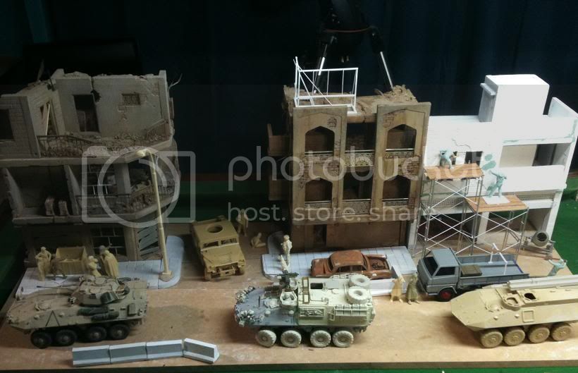
Hello. They are total scratchbuilds. I designed and cast each of them myself. Many many hours of researching middle eastern architecture for authenticity. I have alot of in progressphotos taken with my iphone, which I will post eventually in the diorama forums. Until then there were some other photos I posted in this thread here https://armorama.kitmaker.net/forums/166730&page=1 check that out for some detail pics of the corner building.
As said before buildings are far from done - lots of signage and weathering to do, plus electrical fittings and power cables etc etc..
I have a philosophy on dioramas. basically the base and building should be treated as a model in itself, it should be able to stand on its own as a model with all the accuracy, interesting detail and effort that goes in to the vehicles displayed. Too many dioramas have great models on terrible bases , something slapped together as an afterthought. I believe that if the diorama base is good enough, you should be able to remove the military vehicles and replace with anything and it still has context and interest. just a thought . I will definitely detail those more in the diorama thread !
Thanks for your comments
Adam

retiredyank

Joined: June 29, 2009
KitMaker: 11,610 posts
Armorama: 7,843 posts
Posted: Friday, December 31, 2010 - 12:50 AM UTC
Only way to go comments from me Adam. A very thorough blog, so far. I have always found Trumpeter kits to be a little tricky, but it seems to be going very smoothly for you.

Anirudharun
Joined: February 16, 2008
KitMaker: 597 posts
Armorama: 530 posts
Posted: Friday, December 31, 2010 - 02:15 AM UTC
Great work on the crane mate. The hydraulic lines are very well done.
To be honest I didn't know what I was getting into when I started the interior, but the majority on the components are done now and the white coat is on, so after it dries I have to paint all the small inaccessible bits ...
Also Im having trouble working out which colours to use for the camo scheme and I was wondering which colours you'll be using?
Keep up the good work!
Adamskii
Joined: November 06, 2010
KitMaker: 537 posts
Armorama: 474 posts
Posted: Friday, December 31, 2010 - 12:50 PM UTC
Happy New year everyone! 2011!
headlight assembly.
I hate this part. its fiddly and small and I never get it right. one of the reasons I leave it to last. That said, the brush guards on this kit are resin cast - they are insane! made this part so much easier, if all the kits had this I would of done more.
Anyways heres the pics, step by step how I assmbled them. the photo etch brackets I used the ones supplied in the conversion kit. Pay attention when folding as there is a left and right.

then I fit the leopard style headlamps. These are for the first time hollow and later after painting i will fit the clear lenses. Also In this pic you can see the GPS mast and the AMU bracket on the front of utility box.

Then I fitted the light assembly behind the headlights. I find this fiddly - very hard to do in progress shots of as it requires both hands!


Then I fit the indcators. I also fit the other lock point to the front of the hull

Right brush guard added - very very nice. carefull it is delicate.

I add the left Brush guard. Also In this pic you see the orange reflector above the front wheels there are 3 more , 2 on each side, generally above each pair of wheels.

Rear view mirror left side added. another fiddly assembly - the wire needs to be bent to fit, I have no template but just copied what I did on my ASLAV PC
so its consistent on the diorama.

Add some more details, the wire cutter, and some shackles

Right side mirror added. Of interest I added the phase 3 type mirror mount which is different to the left side. Wire again is bent to match my ASLAV PC.

Lastly the footman loops and antennae configuration on the roof. I absolutely hate doing footman loops and where its an option to use kit supplied pre moulded ones I genereally take it. However as I had to do it on one of the conversions, I have to do it on all 3 for continuity in the diorama. Also added are some small tubes that I think are used as flag holders?

headlight assembly.
I hate this part. its fiddly and small and I never get it right. one of the reasons I leave it to last. That said, the brush guards on this kit are resin cast - they are insane! made this part so much easier, if all the kits had this I would of done more.
Anyways heres the pics, step by step how I assmbled them. the photo etch brackets I used the ones supplied in the conversion kit. Pay attention when folding as there is a left and right.
then I fit the leopard style headlamps. These are for the first time hollow and later after painting i will fit the clear lenses. Also In this pic you can see the GPS mast and the AMU bracket on the front of utility box.
Then I fitted the light assembly behind the headlights. I find this fiddly - very hard to do in progress shots of as it requires both hands!
Then I fit the indcators. I also fit the other lock point to the front of the hull
Right brush guard added - very very nice. carefull it is delicate.
I add the left Brush guard. Also In this pic you see the orange reflector above the front wheels there are 3 more , 2 on each side, generally above each pair of wheels.
Rear view mirror left side added. another fiddly assembly - the wire needs to be bent to fit, I have no template but just copied what I did on my ASLAV PC
so its consistent on the diorama.
Add some more details, the wire cutter, and some shackles
Right side mirror added. Of interest I added the phase 3 type mirror mount which is different to the left side. Wire again is bent to match my ASLAV PC.
Lastly the footman loops and antennae configuration on the roof. I absolutely hate doing footman loops and where its an option to use kit supplied pre moulded ones I genereally take it. However as I had to do it on one of the conversions, I have to do it on all 3 for continuity in the diorama
. Also added are some small tubes that I think are used as flag holders? Adamskii
Joined: November 06, 2010
KitMaker: 537 posts
Armorama: 474 posts
Posted: Friday, December 31, 2010 - 07:29 PM UTC
The build is basically done now. All that is left is to fix up all the screw ups. I will list them afterwards. None of the stowage is done, and this on purpose. I will place the stowage on the vehicles when all three for the dio are built, to make sure I have consistency across the 3, and balance. Same for the antenna masts. All three will be painted together and I have set aside Easter 2011 to do this - so I have 3 or so months to get my markings sorted, stowage , and fix up any outstsanding issues. Models need to be complete by June - Model competition on the long weekend in Melbourne and i want to enter.
As is traditional on most build logs, when finished here are a tonne of walkaround style pics, As if there is anything you havent seen yet via the blog !
If something strikes you as odd or have a question - please let me know and I will address it or offer a reason for it being.
I took pics on an overcast day, unfortunately as soon as i set up, the sun came out so had to shift under the verandah. As Always best pics are taken with natural diffused light. I added a pic of the setup / studio. Photos taken on an 8 megapixel cannon digital SLR, from a distance of about 3 meters using zoom to try and create a larger depth of focus. not perferct but I'm always learning!
Adam


 I'm off for a swim.
As is traditional on most build logs, when finished here are a tonne of walkaround style pics, As if there is anything you havent seen yet via the blog !
If something strikes you as odd or have a question - please let me know and I will address it or offer a reason for it being.
I took pics on an overcast day, unfortunately as soon as i set up, the sun came out so had to shift under the verandah. As Always best pics are taken with natural diffused light. I added a pic of the setup / studio. Photos taken on an 8 megapixel cannon digital SLR, from a distance of about 3 meters using zoom to try and create a larger depth of focus. not perferct but I'm always learning!
Adam
I'm off for a swim. 
sam_dwyer
Joined: November 03, 2008
KitMaker: 294 posts
Armorama: 291 posts
Posted: Friday, December 31, 2010 - 08:01 PM UTC
Happy New Year!
Looking great, i just started mine this arvo.
Great to hear that you'll be over for Expo in June. Drop me a line if you need any info or what ever about the comp.
Hopefully its cooled down where you are - it was 41 deg yesterday, and 24 or something and rainy today. Stupid bloody weather!
SD
Looking great, i just started mine this arvo.
Great to hear that you'll be over for Expo in June. Drop me a line if you need any info or what ever about the comp.
Hopefully its cooled down where you are - it was 41 deg yesterday, and 24 or something and rainy today. Stupid bloody weather!
SD
Adamskii
Joined: November 06, 2010
KitMaker: 537 posts
Armorama: 474 posts
Posted: Friday, December 31, 2010 - 11:11 PM UTC
Hey Sam
yeah the weather is stuffed. lol. Im looking forward to going to Melbourne again - been 5 years since I entered last time. So have a few years worth of trophy winners to bring over!
As for the build - here is the list of known screw ups and forgotten things to be fixed:
trim vane ram needs replacing (mine fell out - forgot to glue after test fit)
shovel in tool rack needs resizing
MEAO comms upgrade to include shark fins
fill a seam on port side edge
wire headlights etc
install the 8 chain keylocks (cant believe I forgot this)
install correct AMU mount for antenna in front of utility box
fix the two mesh grills to have correct bolt pattern and install the lifting rings
Thats about it as far as I can see. Any others anyone sees let me know to address them!
Adam
jashby
Joined: July 01, 2009
KitMaker: 278 posts
Armorama: 248 posts

Posted: Saturday, January 01, 2011 - 12:43 AM UTC
"Also added are some small tubes that I think are used as flag holders?"
Hi Adam. Awesome so far and a joy to follow. Just wanted to let you know that the flag holders are mounts for the VM's work lights. Pretty nifty idea I think. Anyway just wanted to let you as its always interesting to find out what little bits and pieces do.
Just one question, is the AMU on the rear left a folded HF Ant?
Cheers, John
specmod
Joined: August 12, 2009
KitMaker: 93 posts
Armorama: 91 posts
Posted: Saturday, January 01, 2011 - 01:11 AM UTC
Holy cow, that was a fast build for the complexity of the kit and conversion. Well Done mate well done indeed. Come and visit me in Melb comp, I will be working at the Firestorm stand. Cheers Andrew 
Adamskii
Joined: November 06, 2010
KitMaker: 537 posts
Armorama: 474 posts
Posted: Saturday, January 01, 2011 - 01:26 AM UTC
Quoted Text
Holy cow, that was a fast build for the complexity of the kit and conversion. Well Done mate well done indeed. Come and visit me in Melb comp, I will be working at the Firestorm stand. Cheers Andrew
Hi Andrew, thanks for the comments. I am teased by my modelling friends at speed builds. Often they joke the kit is"built before I get it home from the shop".
I'll be sure to say hi in Melb. I will drive over and maybe stay with my brother in law. I'll be doing it as cheap as I can so wont be venturing far from the competition and could well be a fixture there myself. I will do a show report and take a zillion pics so will spend much time seated behind a laptop typing.
Also I like to have a chat with David Hay about the state of modelling and techniques - he has some great advice at times.
Adam
Adamskii
Joined: November 06, 2010
KitMaker: 537 posts
Armorama: 474 posts
Posted: Saturday, January 01, 2011 - 01:36 AM UTC
Quoted Text
Just one question, is the AMU on the rear left a folded HF Ant?
Cheers, John
Howdy John , thanks for clearing up the little holder things - makes sense now I know. Atenna configurations on the ASLAV FOV is niggling nusance for me. I dont know all the correct names, all the correct mounts, and all the specific locations, as well as the rules of employment. And they change so often from one pic to the next its hard to find consistency.
The answer to your question is yes it is - placed there according to the instructions.
I would love to understand the rules of locating "blue force tracker" ant, GPS mount (with and without RWS on type2, and where on bar armoured phase 3 etc) and the other types of mounts, and bases used. I am compiling a small chart to hopefully work this out. eventually I would love to have a plan view map of the top of each car and different typical antenna configurations for troop cars, and the command ones. As Jasmils offers, almost anything is possible with ASLAVs.
I have not placed the antena in the holder in frot of the utility box yet as I have several spare antenna and bases and want to check my references as to the most common one used in IRAQ patrol order.
Thanks for the comments,
Adam
jasmils
Joined: December 23, 2003
KitMaker: 1,016 posts
Armorama: 745 posts
Posted: Saturday, January 01, 2011 - 05:04 AM UTC
G'day Adam,
The instructions are correct. I think you may have gotten this one mixed up. I know I stuffed up a heap doing my build. CT5 (IVNS) should be on the base of the rear left, not CT4 (HF). CT4 sits in the ant mount (CT1) in front of the large bin (CM). I have not seen the HF used in the MEAO. But I did include it in the kit for Australian based Fitters.
My MEAO Comms ACM35858 will be updated in the next couple of weeks to include the placement of the Blue Force Tracker on the F/R and "DUKE" antenna's for gun car's and PC's.
Cheers Jason
PS I wish I could have built my this fast!!!! Nice job. Very nice job.
PPS and for all of those that are interested, I will have 5 view drawings available soon of the three tone camo pattern.
sam_dwyer
Joined: November 03, 2008
KitMaker: 294 posts
Armorama: 291 posts
Posted: Saturday, January 01, 2011 - 08:20 AM UTC
[
HI mate - unless you have a shot indicating otherwise - the round disc you have highlighted here is a reflector, and these were removed before shipping the vehicles to Iraq
Cheers
SD
HI mate - unless you have a shot indicating otherwise - the round disc you have highlighted here is a reflector, and these were removed before shipping the vehicles to Iraq
Cheers
SD
Adamskii
Joined: November 06, 2010
KitMaker: 537 posts
Armorama: 474 posts
Posted: Saturday, January 01, 2011 - 11:03 AM UTC
Quoted Text
HI mate - unless you have a shot indicating otherwise - the round disc you have highlighted here is a reflector, and these were removed before shipping the vehicles to Iraq
Cheers
SD
I thought so too, but there are alot of pics with them still attached. Whoever was responsible for their removal didnt get the standing order? anyways if you have the ASLAV 4 militarybriefs book, pages 101, 102, 106, 111 (top right and a fitters at the bottom), 115, 119x2 and 137 show Iraq op catalyst/secdet vehicles with the orange reflectors clearly visible. There are other pics but is not absolutely clear what the lump is (looks like some have tape over them and it has half peeled off).
These are very very easy to remove so I will go deeper down the burrow on this and check all my reference pics to be certain its a viable attachment. Thanks heaps for the heads up though its exactly what I need to "judge proof" my model.
Adam
Adamskii
Joined: November 06, 2010
KitMaker: 537 posts
Armorama: 474 posts
Posted: Saturday, January 01, 2011 - 11:36 AM UTC
Quoted Text
G'day Adam,
The instructions are correct. I think you may have gotten this one mixed up. I know I stuffed up a heap doing my build. CT5 (IVNS) should be on the base of the rear left, not CT4 (HF). CT4 sits in the ant mount (CT1) in front of the large bin (CM). I have not seen the HF used in the MEAO. But I did include it in the kit for Australian based Fitters.
Yeah I screwed up there, dont know what went wrong, will investigate imeadiately - as there is an ant base left on the sprue but it is short and doesnt look like the IVNS.
Thanks for pointing that out - keep them coming !
Adam
ti

Joined: May 08, 2002
KitMaker: 2,264 posts
Armorama: 1,763 posts
Posted: Saturday, January 01, 2011 - 11:47 AM UTC
I'm really amazed by the amount of detail and work you have put into this. That dio is going to be a masterpiece. Thank you for the inspiration.

 |

WEB HOSTING BY


Copyright ©2021 Armorama and Kitmaker Network, a subsidiary of Silver Star Enterprises
All Rights Reserved. Please read our Conditions of Use and Privacy Policy.
All Rights Reserved. Please read our Conditions of Use and Privacy Policy.