_GOTOBOTTOM
Constructive Feedback
For in-progress or completed build photos. Give and get contructive feedback!
1/35 German G10 covered wagon
grave_digger
Visit this Community
Clare, Ireland
Joined: December 30, 2008
KitMaker: 952 posts
Armorama: 834 posts
Posted: Saturday, April 09, 2011 - 08:43 AM UTC
Its been a while once again since I was building something here, so something fresh to start
This is one of the most known and also infamous German wagons. With some changes of design produced in thousands pieces since 19th century, earlier with brake cab mounted up at roof level, later without it, these wagons were used widely in German rail service to transport goods and often animals as well. During the WWII they became an important part of any military train heading the battlefield, filled with supplies or soldiers, and they were also used to transport all enemies of the nation to concentration camps. Here is one of these wagons, they could vary in small details, depending on manufacturer and year of production. This one shown in German museum has marking of a car captured and used by Allies at the end of the WWII.


Frame assembly

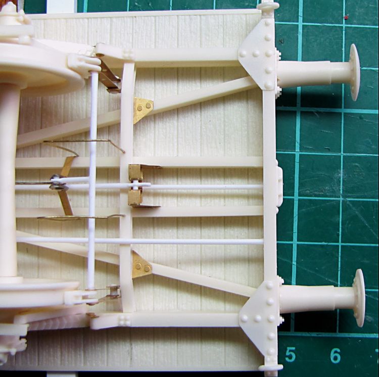
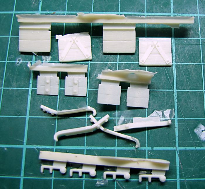
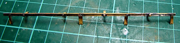
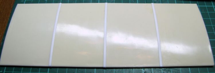
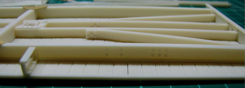
This job is easy, once again it is very important to keep eye on right angle in any corner, also perfectly flat working surface is a need. Just small cleaning where connectors to feeders were placed - these sides will be turned to the floor anyway. I completed frame beams, dry-fitted in assembly slots first, because frame construction needs exactly the same length like floor sections glued together - these are different ones for outside and inside, both by two (if needed, the long beams can be set up by a little sanding) and finally I glued all together.


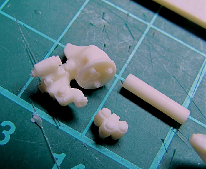
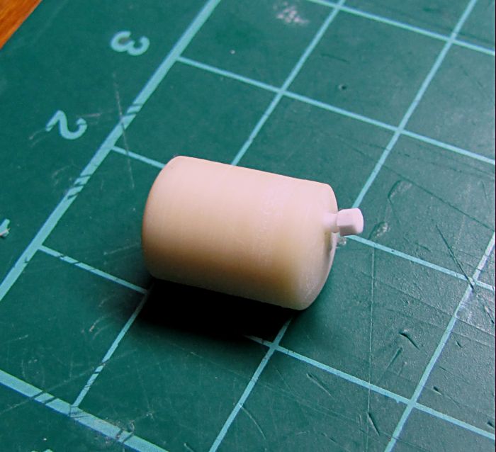
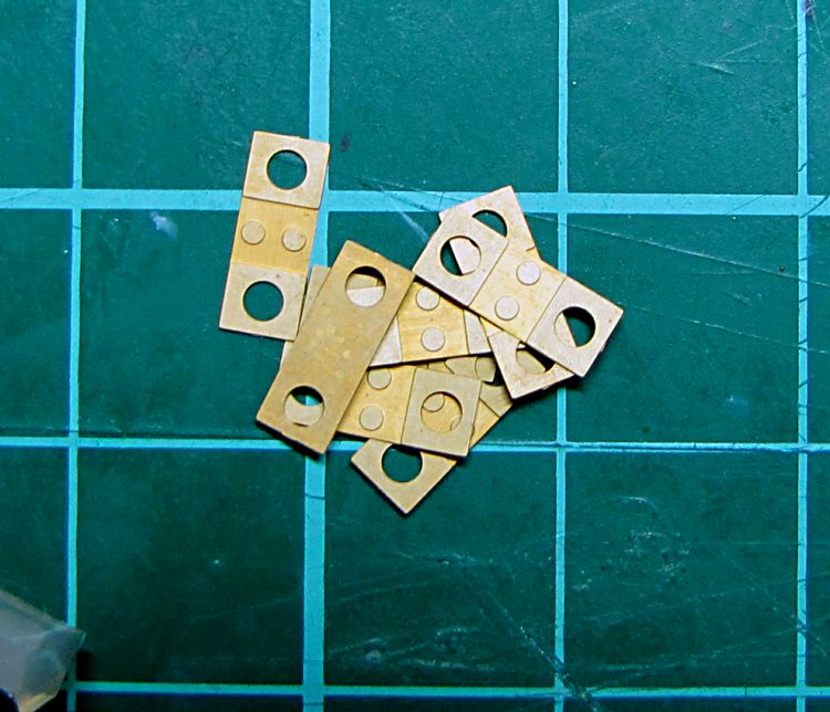
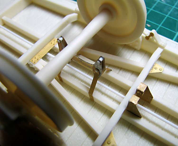
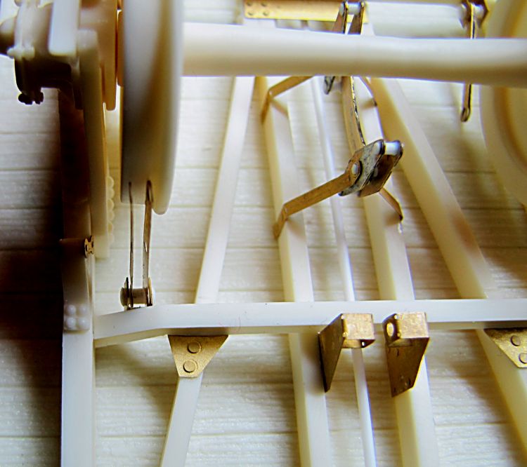
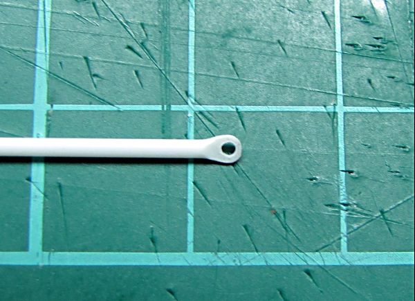
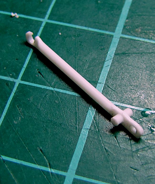
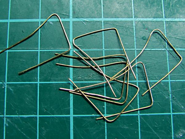
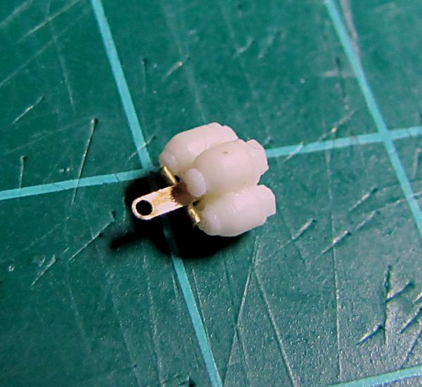
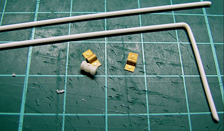
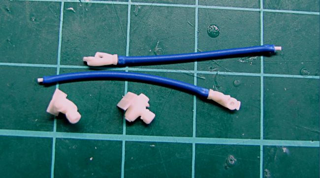
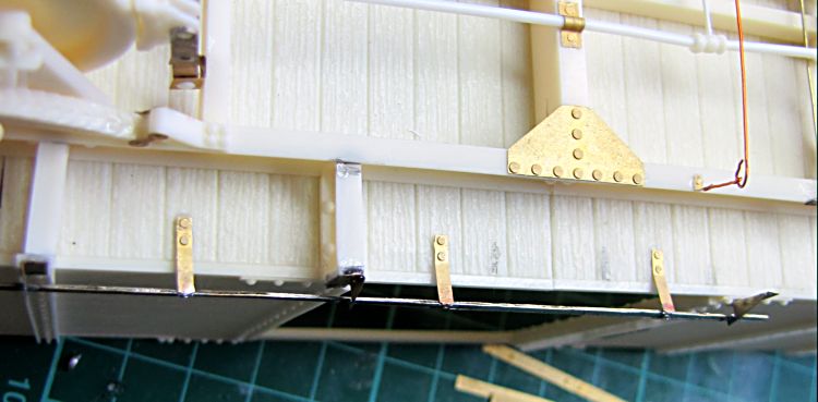
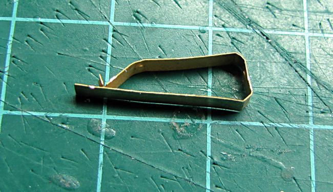
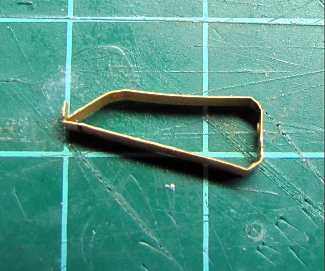
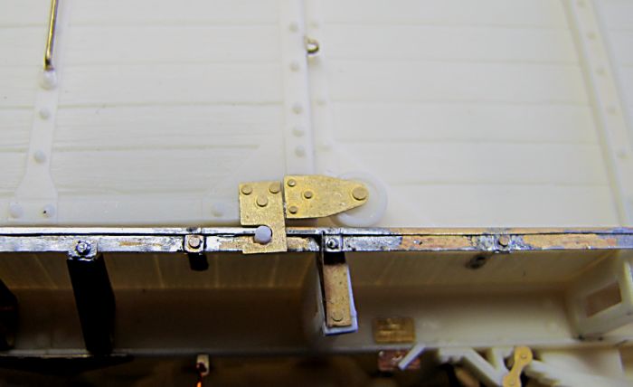
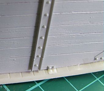
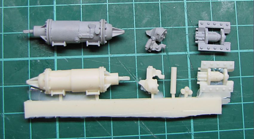
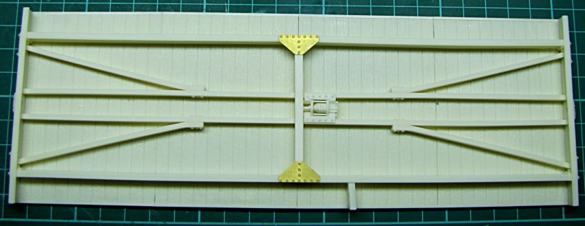
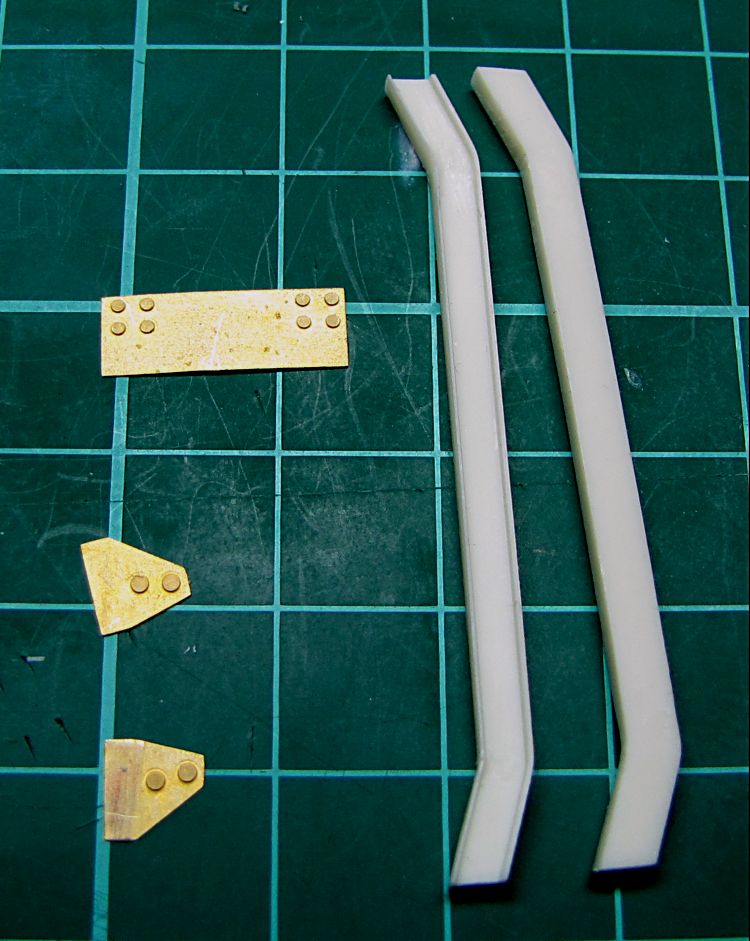
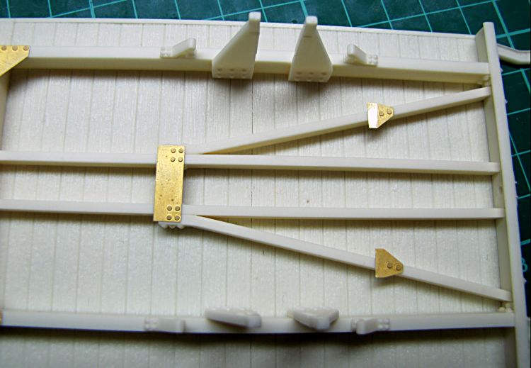
From brake sprue I cut out a hook spring, and glued in two short pieces of plastic rod. It will be glued between central beams and plastic rod will be used to connect it to both hooks. It is simple thing to reduce shocks, when train starts moving. Side channels assembled then. Rivets for spring holders have to be always down, group of 6 rivets needs to be directed out to the buffers at both sides, while groups of 4 rivets are faced inside. Very little sanding might be needed to get exact length of channels - simply any resin castings always shrink a bit, so these parts are about 0,2mm longer than they need to be - to avoid trouble with short sides. All side channels are then glued to the floor, to keep right distance I used one of the short brackets, which will be assebled later - but now it helped well to have sides straight and right. End of this bracket has to stand with edge of the floor. Finally hook spring is glued between beams, and PE reinforcements took their place.


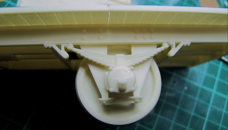
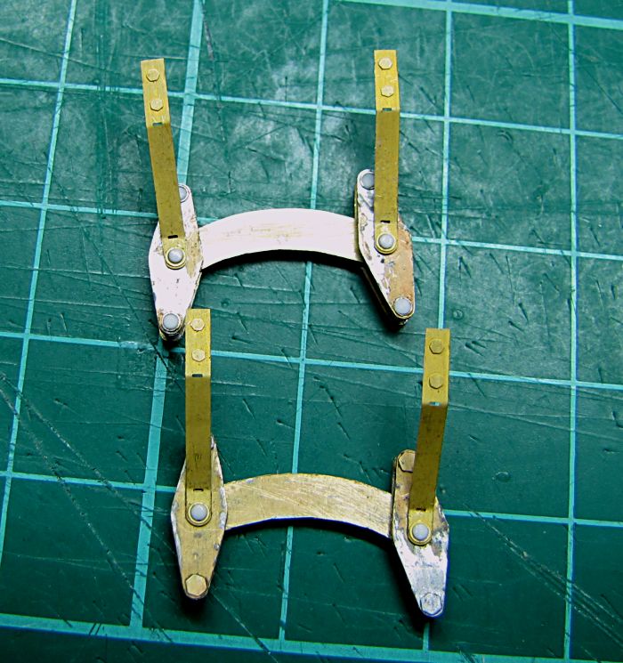
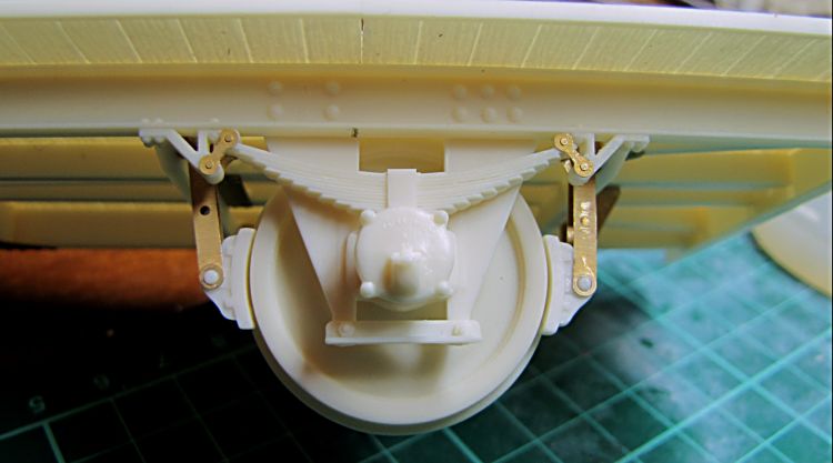
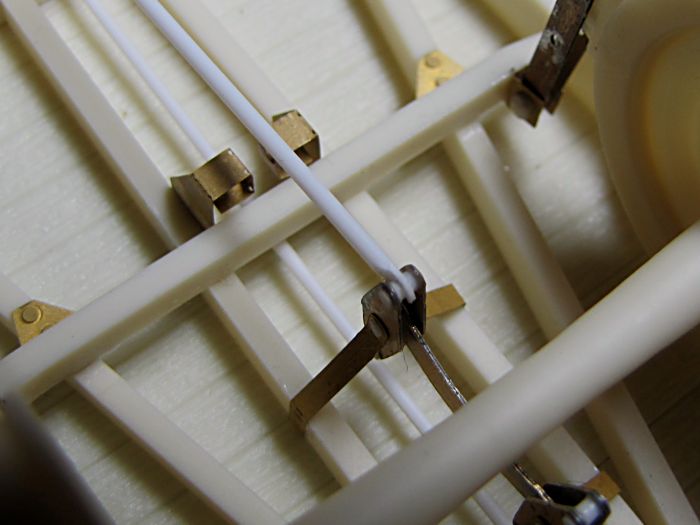
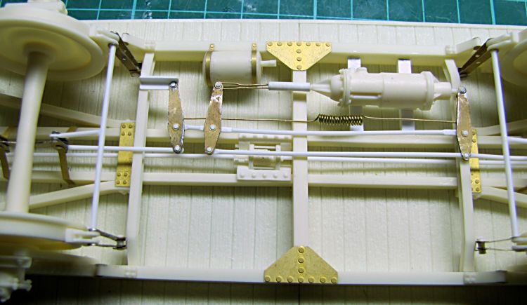
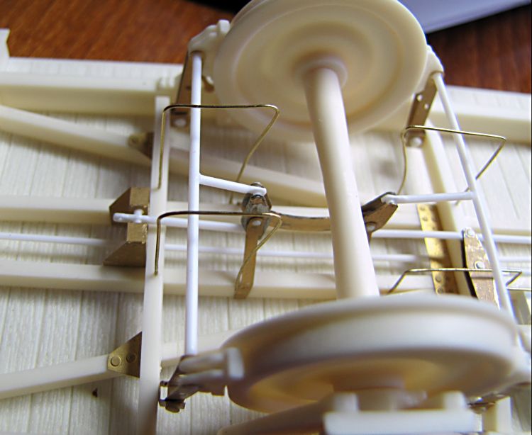
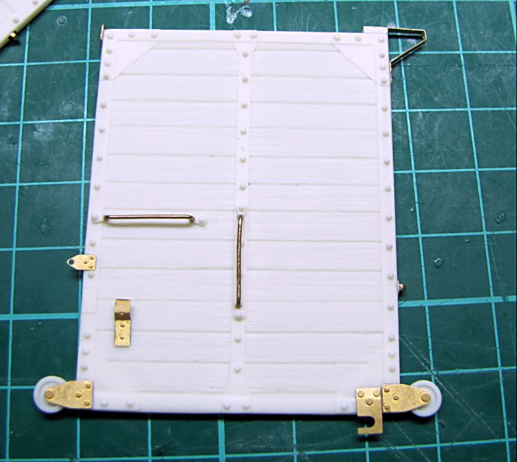
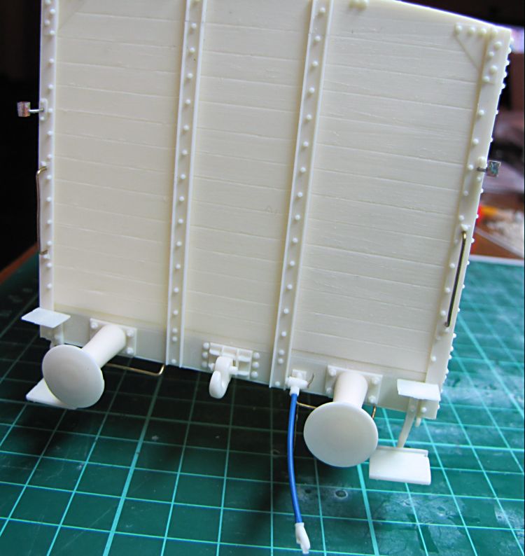
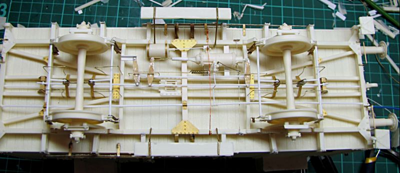
Continued with the chassis, sliders for bearing housings are assembled, and spring hangers then. Rivets on them corespond with rivets on side channel, what makes assembly very easy. Cross beams are to be fitted just like seen in pictures, they all are mounted on PE reinforcements. Wheels with axles and bearing housings dropped in place then with springs to check dry fitting. These will be glued in my next step and all secured with brackets. Lettering - cast firm name of Czech well known industry manufacturer - is nicely reproduced in resin as well.


More next time
Cheers
Libor
retiredyank
Visit this Community
Arkansas, United States
Joined: June 29, 2009
KitMaker: 11,610 posts
Armorama: 7,843 posts
Posted: Saturday, April 09, 2011 - 09:38 AM UTC
Always look forward to seeing your work Libor. I did notice that the bottom set of axel and wheels has quite a gap. Is this just dry fitted or is the axel too short? Anyways, looks to be an amazing one of your builds.
grave_digger
Visit this Community
Clare, Ireland
Joined: December 30, 2008
KitMaker: 952 posts
Armorama: 834 posts
Posted: Saturday, April 09, 2011 - 09:54 AM UTC
Hi Matt,
thank you for your kind words. It was just dry-fitted in that picture. Wheels can be actually secured with a drop of glue on the axle, which is still free turning in bearing housings.
Cheers
Libor
grave_digger
Visit this Community
Clare, Ireland
Joined: December 30, 2008
KitMaker: 952 posts
Armorama: 834 posts
Posted: Monday, April 11, 2011 - 09:52 AM UTC
Build continues....
Worked with PE parts, I have assembled holders for brake equipment, and spring holders on bogies. Now I will start brake system


There are plenty of PE parts involved in brake system. I decided to go for soldering this time. Have not use this technology often so far, but everything went all right. I used plain solder and solution recommended by my friend earlier. Just few drops on and then very thin layer of solder on both - I stuck both halves together and warmed up, melted solder joined pieces together without any excess. Then I just checked edges and cleaned pieces with fine sand paper. Everything is ready for assembly now.

For the pins 1mm diameter styrene rod used. In my case it is partly glued and partly fixed by melting of styrene using a lighter


Brake arms completed with couplers, then their hangers mounted on on both sides and finally whole things assembled on chassis. Once finished, I glued on place brake block“s hangers and at the end the blocks themselves. All fixed with drop thin C/A glue to keep brakes in right position.


Thank you for looking in, more to come soon
Cheers
Libor
grave_digger
Visit this Community
Clare, Ireland
Joined: December 30, 2008
KitMaker: 952 posts
Armorama: 834 posts
Posted: Monday, April 25, 2011 - 08:49 AM UTC
Now I should have mentioned assembly of brake operating rods. 1mm rod is flattened in small pliers. Then I drill 1mm diameter hole for a pin, which will be mounted between two arms. But this needs to be done before these arms are completed together. Another way is similar, but seems to be easier and works just perfectly. Here is also hole drilled in flattened plastic rod, and then partly opened - rod can be just clicked in right position on pin connecting two brake arms.


I have assembled all operating rods for brakes, there are only two left to connect whole system to cylinder operating arms later. Then I added air tank with PE brackets and plain brake cylinder. It is mounted on two styrene strips and short cylinder rod is fixed about 1mm above frame cross beam.


Brake operating arms and rods - once again I used 1mm styrene rod flattened where needed. First I cut the lenghts taken during dry - fit assembly, then I glued these rods on botom parts of PE arms together with spring made of 0,4mm brass wire, and finally put on oposite ones. For pins I used thin slices of 1mm rod glued in holes in PE parts. Whole thing was placed in position, rods connected to brake operators, and at the end I added front cylinder driver made from bend brass wire.


More work with wire followed, I glued on simple security brackets for cylinder arms and also brackets for brake block rods.


Now I added PE handles to brake regulators, and short piece of wire got the right look of it. Both regulators are assembled on the cylinder, now I made up a rod for brake equipment air depletion valve, 0,3mm copper wire used. The same one was handy to make short hangers and finally all was assembled together and fixed with drop of C/A in valve lever hole.


All right, thats it for now, more to come
Cheers
Libor
milvehfan
Visit this Community
North Carolina, United States
Joined: June 26, 2007
KitMaker: 2,116 posts
Armorama: 1,080 posts
Posted: Monday, April 25, 2011 - 09:12 AM UTC
Libor,
I always enjoy following your builds. Thanks for shareing this. milvehfan,
grave_digger
Visit this Community
Clare, Ireland
Joined: December 30, 2008
KitMaker: 952 posts
Armorama: 834 posts
Posted: Monday, April 25, 2011 - 10:24 PM UTC
Hi milvehfan
thank you for watching and the kind words. More to come soon. Besides it, G10 wagon reviewed by Bill Cross can be found here at Armorama:
G10 review
Cheers
Libor
grave_digger
Visit this Community
Clare, Ireland
Joined: December 30, 2008
KitMaker: 952 posts
Armorama: 834 posts
Posted: Saturday, April 30, 2011 - 06:23 AM UTC
Well, here is another update:


Continued on chassis, I have assembled brake power switch operating rod and connected to the switch itself. Then I glued on air line made of 1,2mm styrene rod and fixed with PE brackets. Pipes to connect all the parts are made from 0,6mm styrene rod. Also small hangers in frame corners have taken place. My work on underneath is almost finished. I have just added levers to operate brake switch - made of a tiny bit of plastic rod. Also riveted reinforcements to support compactness of the chassis have been added.


This is for the chassis, to be continued soon again....
Cheers
Libor
grave_digger
Visit this Community
Clare, Ireland
Joined: December 30, 2008
KitMaker: 952 posts
Armorama: 834 posts
Posted: Sunday, May 08, 2011 - 08:11 AM UTC
Lets build the walls...
Riveted metal strips to hold together wooden planks are part of castings, and they have to face the interior. First and last narrow side sections show tiny riveted angles - front and rear wals are to be fitted in the slot. This allows to adjust width of the walls if needed - just to meet exactly the width of the floor. Dry - fitted first, and then secured with a few drops of super thin C/A. Opposite wall assembled as well, nad now is right time to start with other wall sections. Usually I do dry fit for any part first, when everything is all right, I glue pieces together - always keeping eye on right angles everywhere. Wall section glued on one by one, and then riveted strips from inside and channels from outside mounted. The last ones are designed on the top to meet a metal strip lined around wagon sides below the roof. To make roof masters I used metal sheet, which made pretty nice metal looking like surface.


Cheers
Libor
grave_digger
Visit this Community
Clare, Ireland
Joined: December 30, 2008
KitMaker: 952 posts
Armorama: 834 posts
Posted: Tuesday, May 17, 2011 - 08:25 AM UTC
Now there are more small parts to start with. Before that I went for sliding doors. 0,6mm wire used to make handles, most PE parts assembled and supporting wheels fitted. Both doors completed and ready to be mounted on, also riveted channels glued on front and rear wall. These are a bit longer than the channels used on sides. Then I got ready some small pieces for later, stepboards, air hoses made of suitable wire isolation, air valves and few more things. PE parts for sliding doors are also ready


Started with a rail for sliding door. First I soldered 4 holders - 2 left and 2 right ones - noticable in the picture, these will be glued inside the channels, so I took exact proportions between them from my build. Then I soldered 4 supporting holders, which will be mounted on bottom floor later. There will be two other holders, but they are more complicated, and I will add them later as well. Below the floor a frame like holders are mounted. These are left and right ones, and their assembly is well shown in pictures. Just four of them 2+2 need a piece of 2,5x0,75mm styrene strip, they will be mounted below the doors, where long side channels are not presented.

Assembling the rails - I simply glued first two holders on the right into channels, then I secured holding strips with C/A, and finally glued two other holders on frame like parts with styrene strip I had ready from previous step. Then I took distance from wagon chassis side channel to the rail, using a piece of styrene strip. I used its length to bend the other holders. I checked a few times to get right shape, then I cut out leftover of PE part and soldered it together. Finished bit was assembled on the rail - using solder again - and the rest of it glued in place.


Cheers
Libor
vonHengest
Visit this Community
Texas, United States
Joined: June 29, 2010
KitMaker: 5,854 posts
Armorama: 4,817 posts
Posted: Tuesday, May 17, 2011 - 03:51 PM UTC
Excellent work Libor. I was hoping you would take on another project like this, particularly this one.
MrMox
Visit this Community
Aarhus, Denmark
Joined: July 18, 2003
KitMaker: 3,377 posts
Armorama: 1,088 posts
Posted: Tuesday, May 17, 2011 - 07:55 PM UTC
Awsome work Libor, really looking forward seeing some paint on it - the weathering possibilities are endless.

Cheers/jan
grave_digger
Visit this Community
Clare, Ireland
Joined: December 30, 2008
KitMaker: 952 posts
Armorama: 834 posts
Posted: Friday, May 20, 2011 - 05:08 AM UTC
Jeremy, Jan, thank you guys for your kind comments. I agree, any rolling stock offers great possibilities for painting and weathering, also without much extra effort it is easy to do some good loking realistic damage - just like the real thing. Unfortunately I did not get to painting stage with this one, it was taken in surfacer coat to modelling show in Vienna, where I used it as a donation for my German business partner company
But I am sure some of these will show here sooner or later in another topic
Cheers
Libor
grave_digger
Visit this Community
Clare, Ireland
Joined: December 30, 2008
KitMaker: 952 posts
Armorama: 834 posts
Posted: Saturday, May 28, 2011 - 08:12 AM UTC
Well, time has come to finish this one....Most parts assembled, stepboards, handles, air hoses and others. Many of these were welded on the wagon body, so I used a good bit of glue to get these joints looking like that.


And more bits added and then surfacer coat applied


The roof: first I glued sections together, then I assembled roof rails made of 1,1x1,6 styrene underneath and finally 2,5x0,25mm strips to secure "metal sheets covering top of the roof". It would be nice to add rivet lines in the centre of every strip. For my build I used only plain roof castings, but final moulds will have riveted lines on their sides. These roofs used to be covered with 1-8 metal sheets, depending on wagon, manufacturer and so on. In many cases just tar paper was used.


Finished roof glued on, using 5 min. epoxy, first one long side. When cured, I used hair dryer to heat up slightly other three sides of the roof in a few steps - when resin got a bit softer, it sat down perfectly on sidewalls without any gaps. It does not mean that fitting was bad, there was just tiny gap at one side - resin cures few days, and any piece can bend during this time more or less - its just good to know that it can be fixed easily. It works perfectly with styrene as well, and I remember I used this way to fix some parts of Morser Karl I built couple years ago. When all glued together, I chopped short pieces from riveted strip, and placed them in their positions - where the opposite ones are cast on sidewalls. At very end I made 4 pieces from 2,5x0,5 styrene, drilled holes in them and mounted them together with 0,6 rod to make up sliding rod for the doors. Then PE cover was added, and surfacer coat sprayed over it. Now my building here is finished


Thank you all for watching and your kind comments
Cheers
warreni
Visit this Community
South Australia, Australia
Joined: August 14, 2007
KitMaker: 5,926 posts
Armorama: 712 posts
Posted: Saturday, May 28, 2011 - 10:14 AM UTC
Hi Libor.
Just found this build log. Can't wait for mine to get here. Will look great behind my BR52.
I have all the PE stuff for the BR52 from Eduard and Voyager and I am thinking of a diorama with two BR52s and a heavy load... That'll take up some space!!
grave_digger
Visit this Community
Clare, Ireland
Joined: December 30, 2008
KitMaker: 952 posts
Armorama: 834 posts
Posted: Tuesday, May 31, 2011 - 08:41 AM UTC
Hi Warren
thank you for your input, I hope you will receive your package in no time - also looking forward to see some pictures of your build then
Cheers
Libor
 _GOTOTOP