1/35 AFV Club M115 8 inch Howitzer
Introduction
Originally designated M1 8 inch howitzer, it was developed during the 1930s. It saw service during WWII & Korea. It was towed by either the M4 18 ton tractor or the 7 ½ ton truck. It was also possible to be towed with the M35 prime mover. During the late 50s and 60s the weapon served in NATO as a nuclear artillery weapon. The M115 upper carriage and gun was used on an M4 chassis to produce the M43 8 inch HMC. Later the same upper carriage and gun were mounted to form the M110 8 inch self propelled howitzer.
The same lower carriage and upper carriage were used to create the M59 155mm gun, originally designated M1. Also, the same upper carriage mounted on the M110 with the 175mm gun made the M107 self propelled gun.
The M115 remained in service with the US military through the early 1980s and has seen and is still in service with many other countries worldwide.
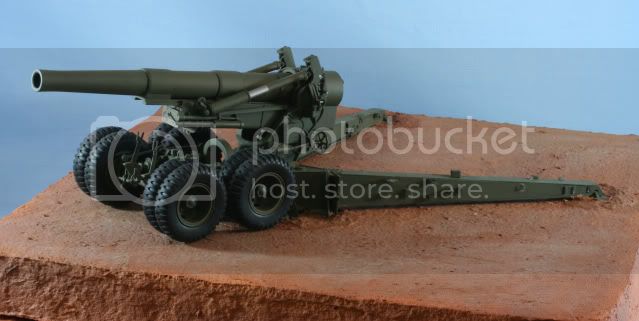
Below, is an 8 inch howitzer in service during the Korean war and the basis of this build

The build
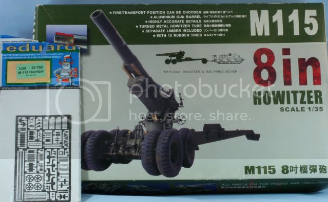
I will be using the AFV kit with Eduard photo etch.
I started by skipping the first few steps, which are the upper carriage and barrel and moved to step 4 which begins the lower carriage. The first two are steps are 4 & 5 which deal with the assembly of the trails. Since I will be using the Eduard PE set, the clips to hold the spades in transport mode were not used in favor of the PE versions. Here is the bare styrene assembly
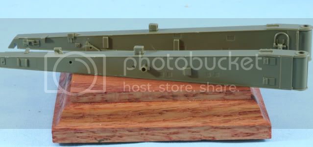
After assembly of the PE parts, here are the trails

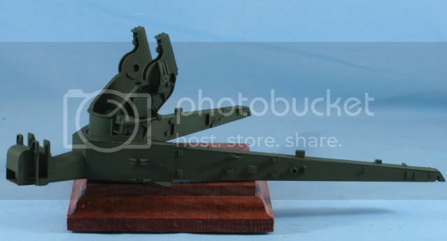
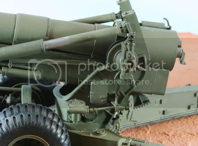
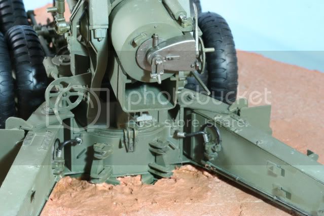
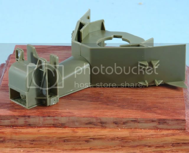
Step 6 is the assembly of the forward section of the lower carriage. Part of this step requires connecting the trails, which are locked in place by part A31. In order to facilitate painting of the trails, I will leave the trails separate and at least prime the trails OD before finalizing this assembly. Part A5 will have some ejector pin marks, which will require filling. Here is the forward end prior to paint.
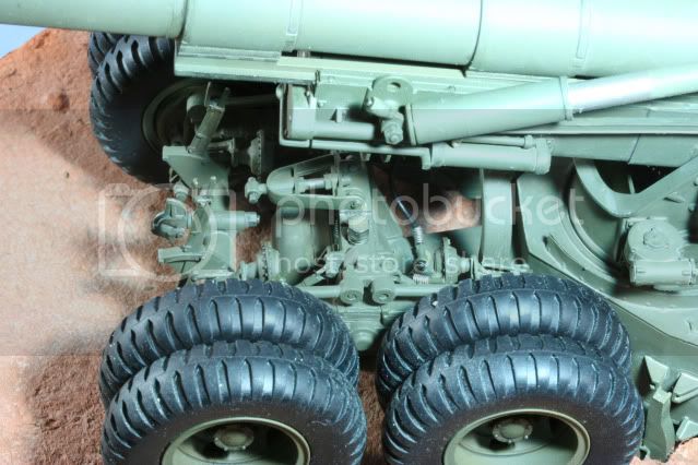
Step 7 is the frame assembly for the wheel carriage. Care needs to be taken with some of the suspension arms and their removal from the sprue. Also parts B40 and B42 need to be checked for ejector pin marks.. Here we are after step 7
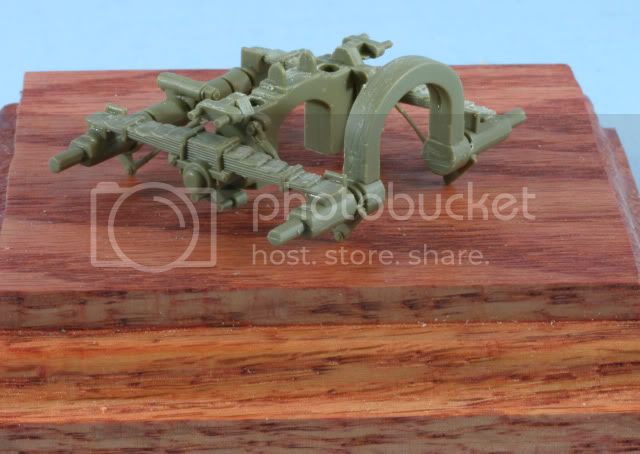
Step 8 assembles the brake system to the wheel carriage. I will be adding the brake lines later but pay attention to the brake assembly part B4 and its direction. There is a nub on one side for the connection of the air line. This should be pointing inward or each side is a mirror image. The instructions show this incorrectly.
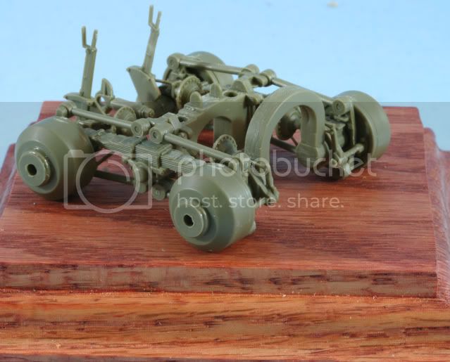
Step 9 is the assembly of the wheel drums and stabilizer arms. Here is the completed step 9 assembly
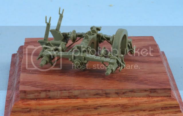
While waiting for glue to dry on the above assemblies, I skipped to Step 14, which is the assembly of the transport trailer. The main part B18 requires a bunch of care to remove the mold seams and filling a sinkhole at the pintle connection. I replace the handles, parts B20 and B17 with SS 20 gauge wire. Also if you look at photos of the trailer (I used my personal and also Prime Portal) there is a long handle on each side of the yoke to allow the crew to lift and move the trailer. I added this with the same 20 gauge wire. The yokes were drilled to accept the wire handles. Rims and tires were left off to facilitate painting.
This photo is prior to filling the sinkhole and adding yoke handles, more of the straight styrene assembly

Well thats it for now. I am off and building for 2012. Next will be to move the lower carriage parts in for priming and go back to assemble the upper carriage.
As always all comments are welcome
Rounds Complete!!