Sorry about the few-weeks gap, but RealLife got in the way!

Anyhow, on with the show...
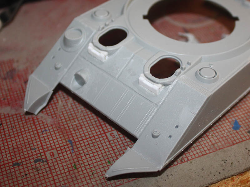
Part 5 bringing up the rearAs I said earlier, the rear lower hull details needed revised. Normal folk would have done this
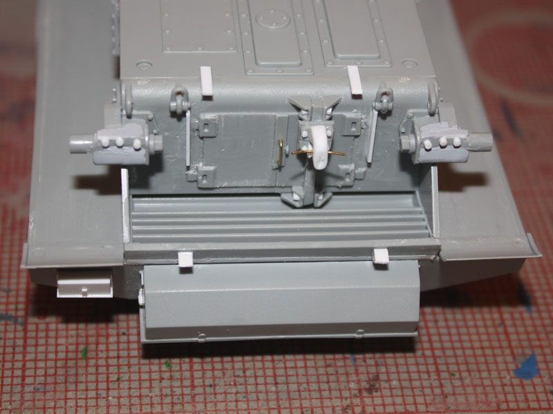
before gluing it into a tight spot at the back of a tank! First off, the mountings for the leaf-spring had to go, with very careful chisel work. Then came those solenoids for the smoke launchers, moulded onto one of the engine doors since Adrian hasnt fitted them I needed to remove them too. While I was at it the lumpen handle on the doors had to go, replaced by wire.

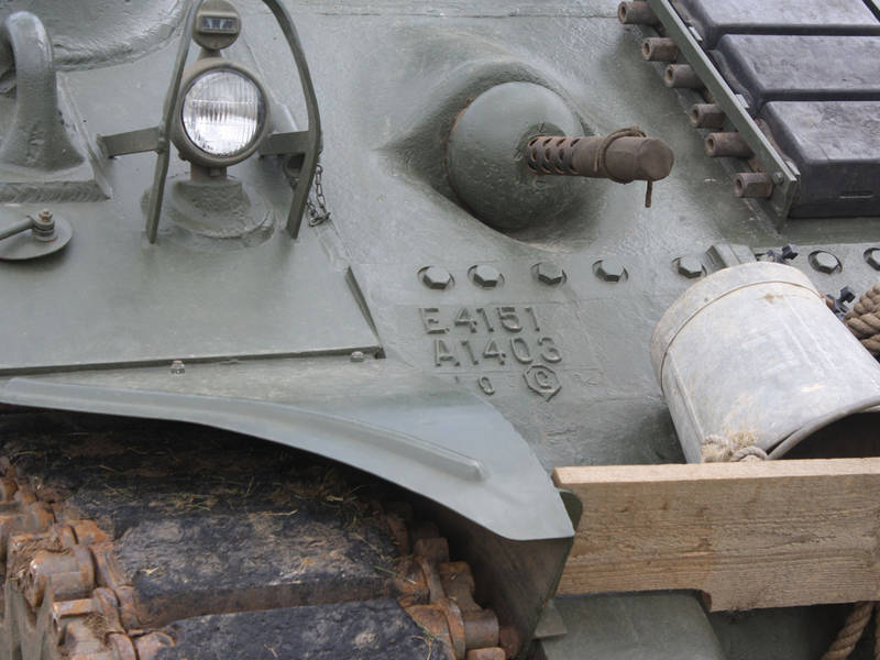
Then things got tricky I needed a tow hook. As usual, the Tasca M4A4 has one, but the Cyberhobby kit doesnt. So I whittled one from thick Evergreen strip, added some bolt heads from hex rod, and lowered the mounting plate to the base of the vertical post as per photos in Alan McNeillys
walkaround here on Armorama.
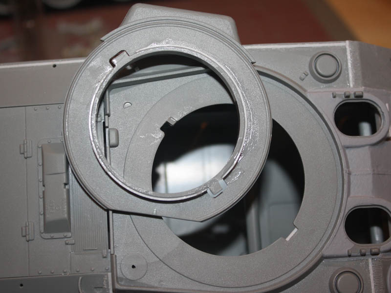
More bolt heads were added either side of the brackets holding the ends of the vertical bar, and the actual brackets got reshaped. While I was at it I also re-sculpted the idler axle mounts because the kit parts bear no resemblance to the real thing!
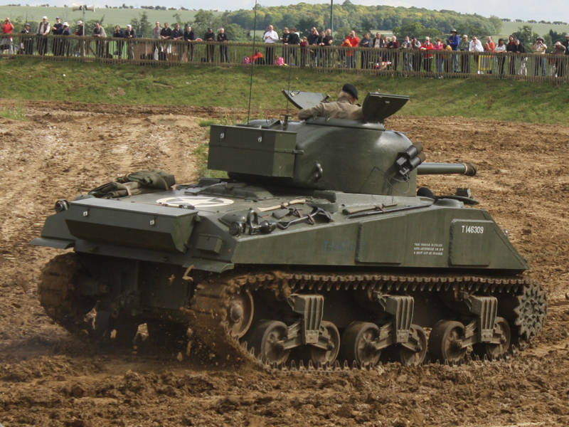
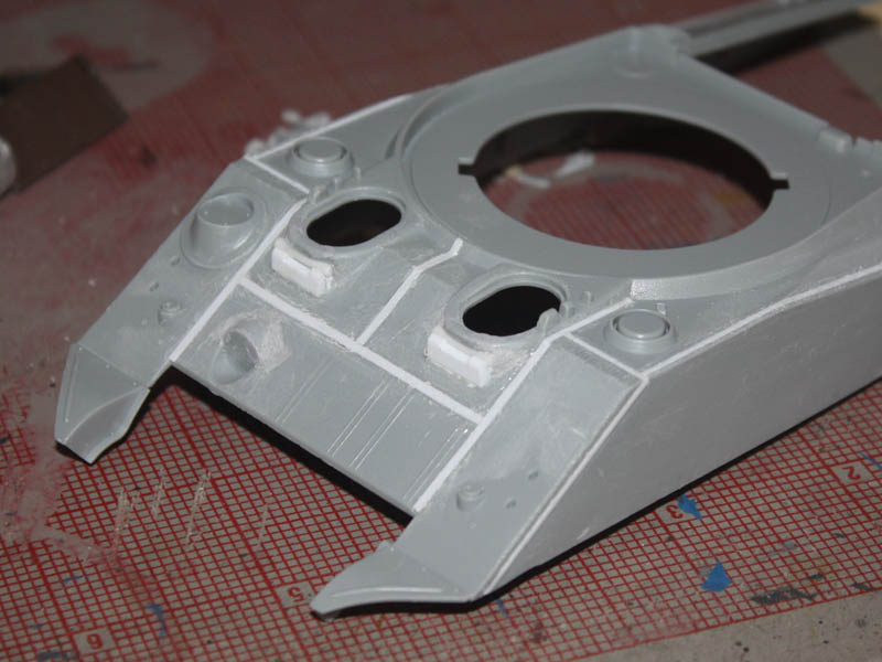
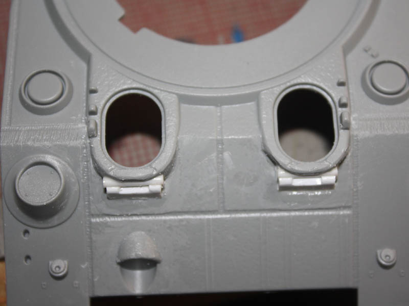
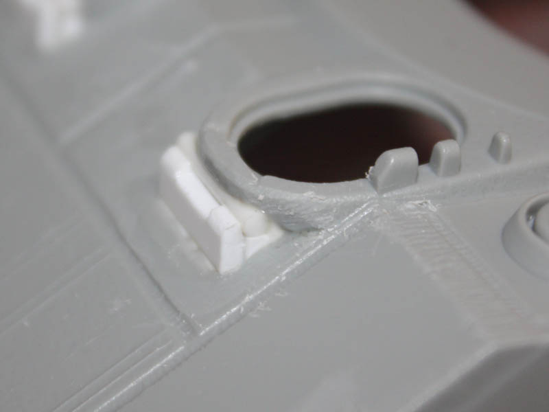
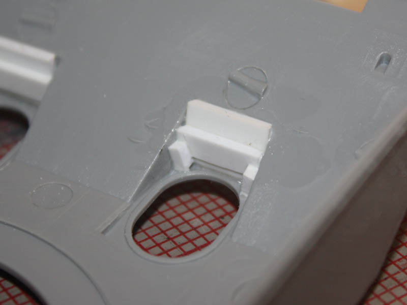
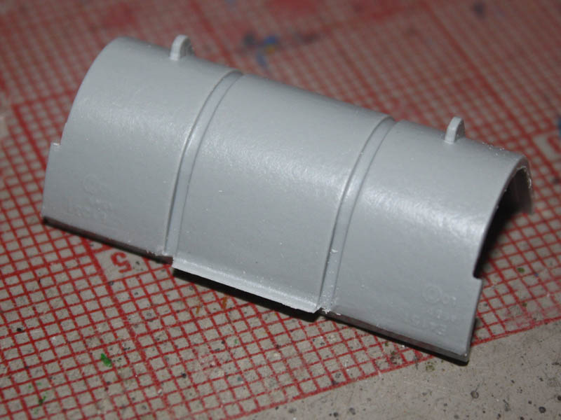
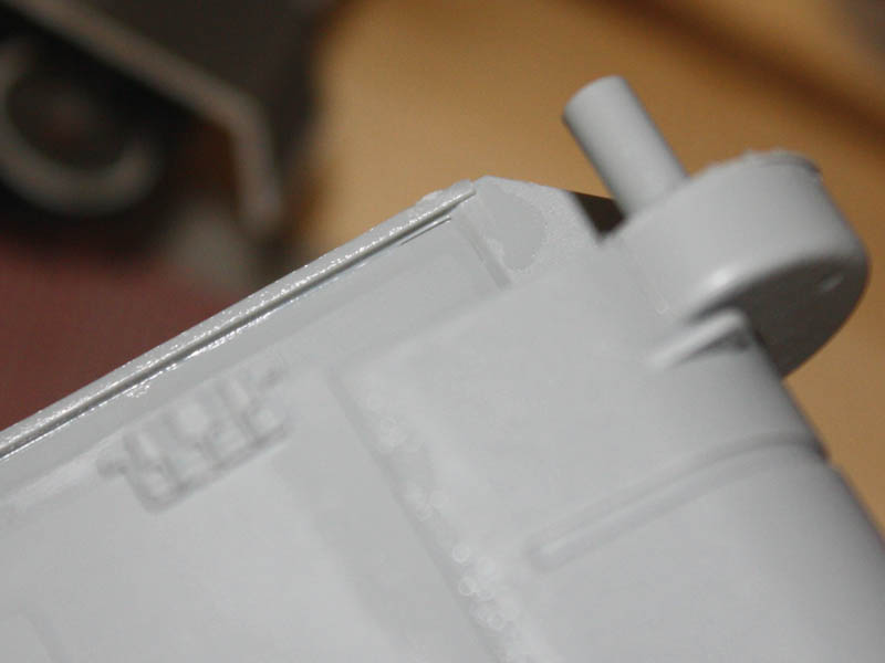
The rear of the upper hull needed a big horizontal weld across it. The earliest of these tanks originally had plates that were level across at the base of the sponsons, but were then extended in the middle by welding on an extra plate to provide some cover to the air cleaners etc below. I took some 0.005 sheet and cut off a thin strip, gluing it in place before using a file to really thin it down to a slightly raised scar.
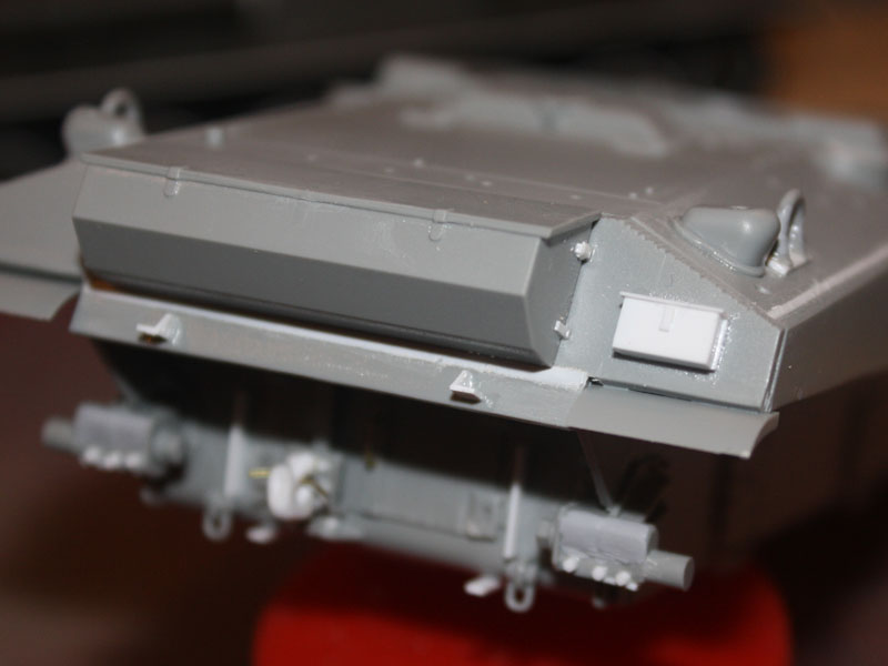
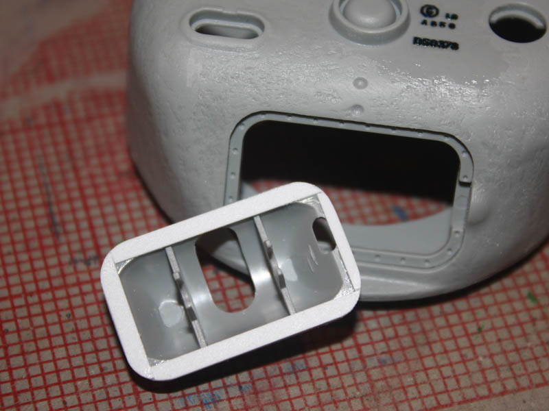
The CH toolbox had a central latch that had to go, and I needed to add some attachment details to the sides. The first-aid box I made from scratch a slab of 0.080x0.125 strip topped with an 0.015x0.100 lid.
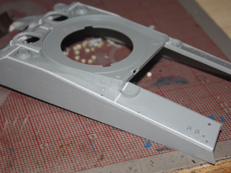
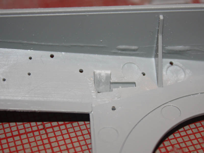
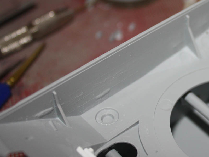
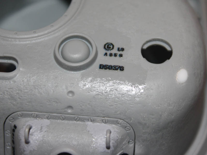
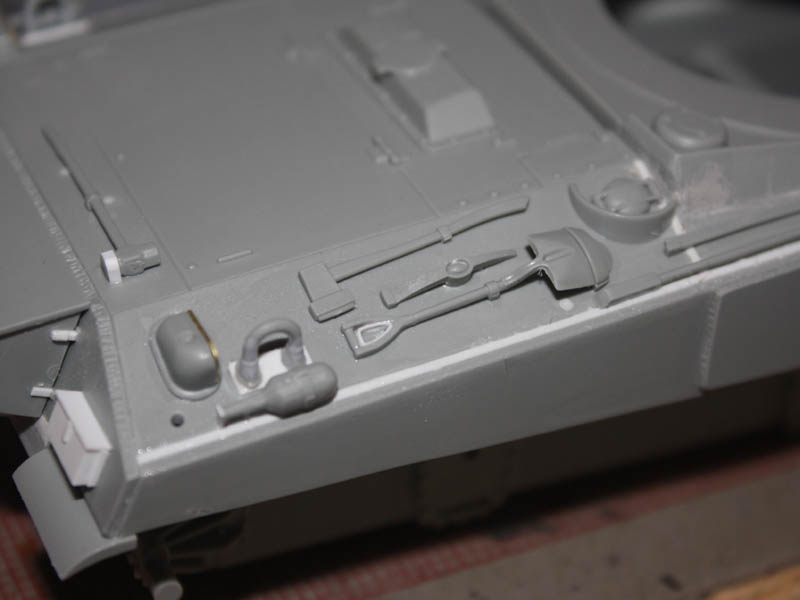
Happy with the rear hull, I turned to the tools and such on the rear deck. Had I paid attention Id have noticed all the really big peg holes that dont necessarily get covered up by the parts, and Id have plugged them before I got this far, but wheres the fun in that? Instead, I got to stuff plastic rod into holes and carefully scrape it flush with other details in the way
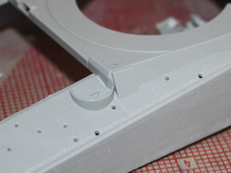
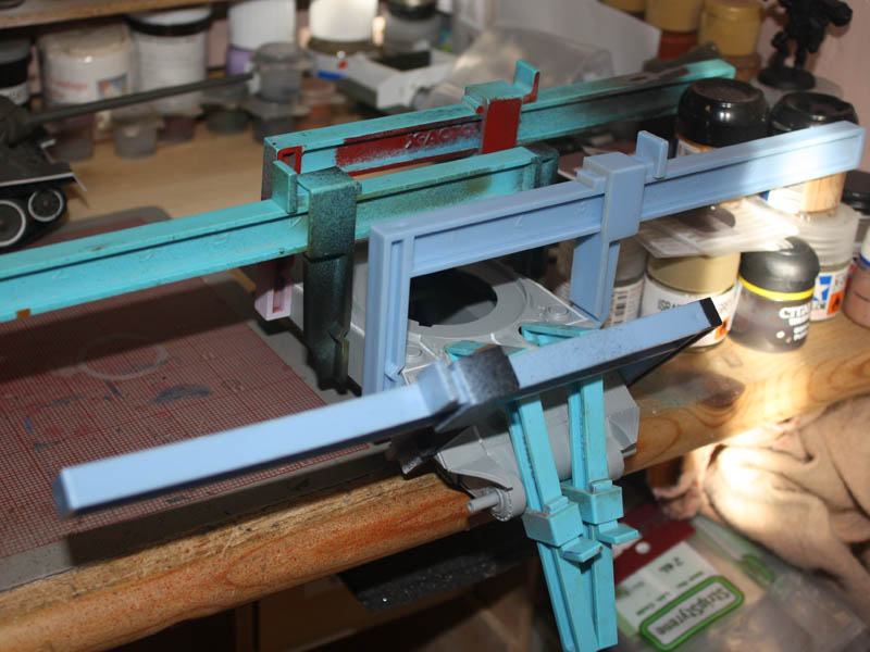
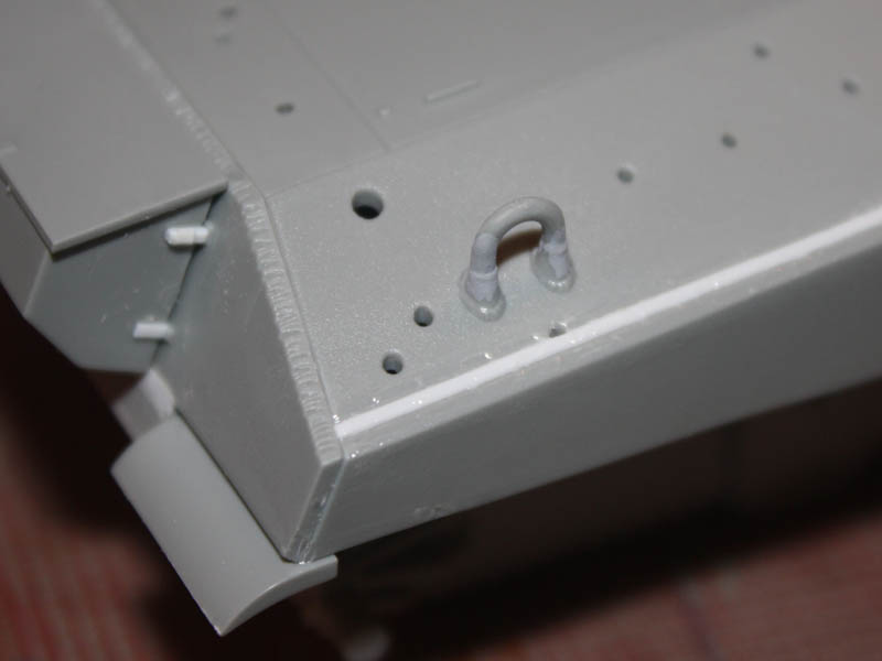
The first thing I did was glue the lift rings in place because the bases are moulded to the hull. The joints are very awkward and weak, but it was essential to leave these to harden overnight so I could then chisel the whole lot off to slip a plate of plastic strip under it.
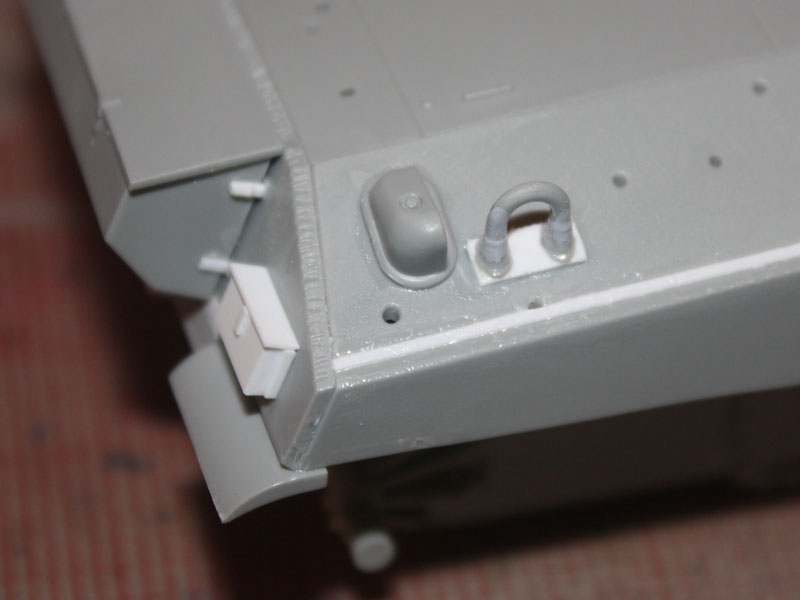
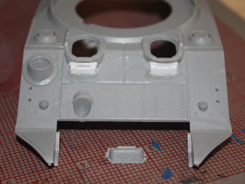
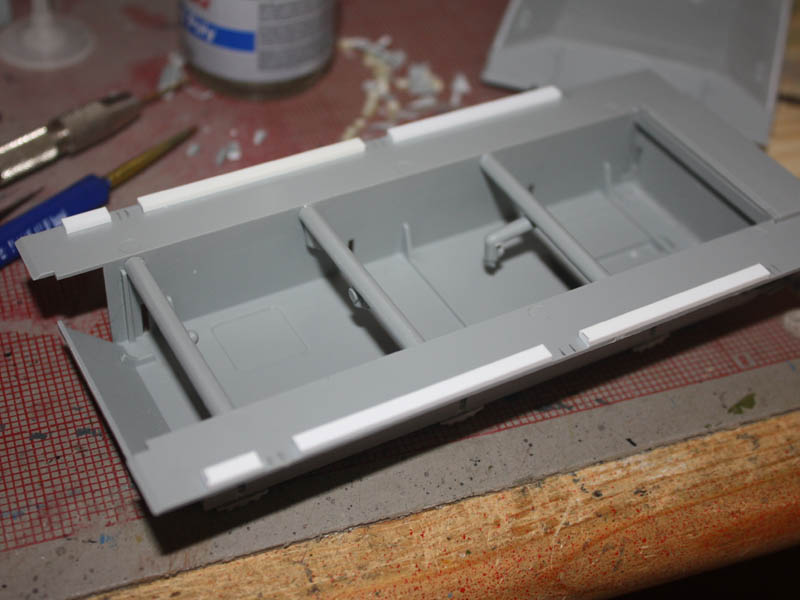
Then I added the grouser vent covers, and found the first offending peg holes to plug. I noticed in the pics that this tank does not have the mountings for a track spanner on the rear deck, so the holes and the round peg had to go.
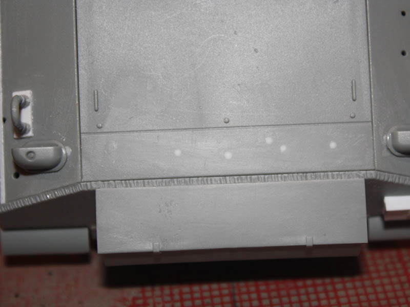
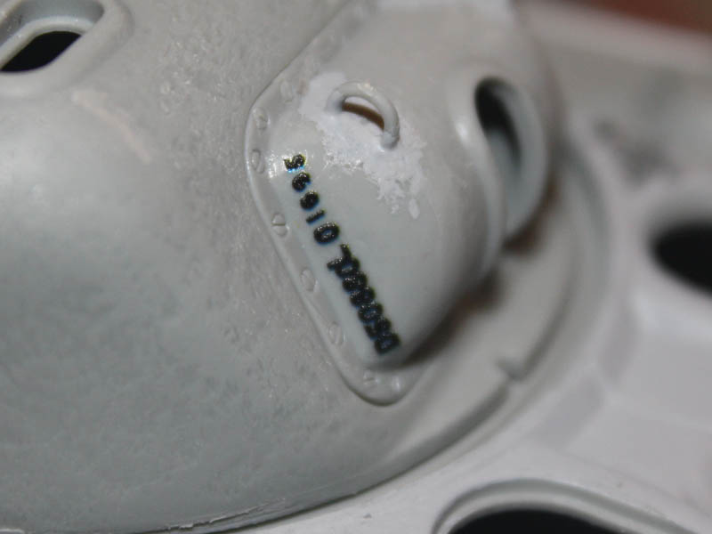
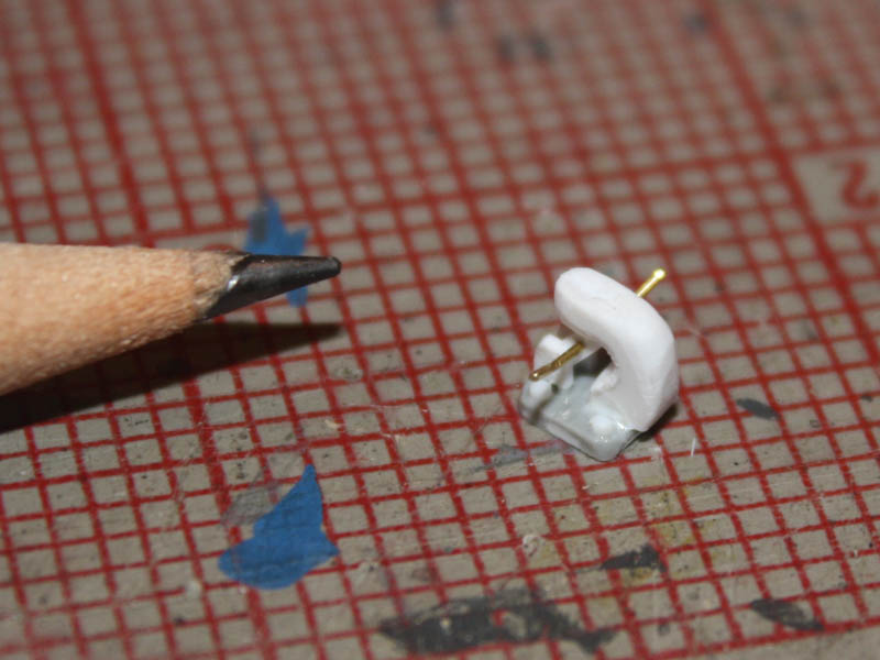
The fire extinguisher bottles either side of the lift rings needed a bracket 0.010x0.040 strip to the rescue! As for the choice of tools, there are three of most in the kit, so I picked the ones that looked most like what I saw on the real one. Note that the two holes on the left shoulder of the hull are for cleaning rods specific to the Firefly version, and need to be plugged. Straps are lacking, as are the cleats to tie them down, so I made mine from 0.010x0.040 strip and 0.020 rod.
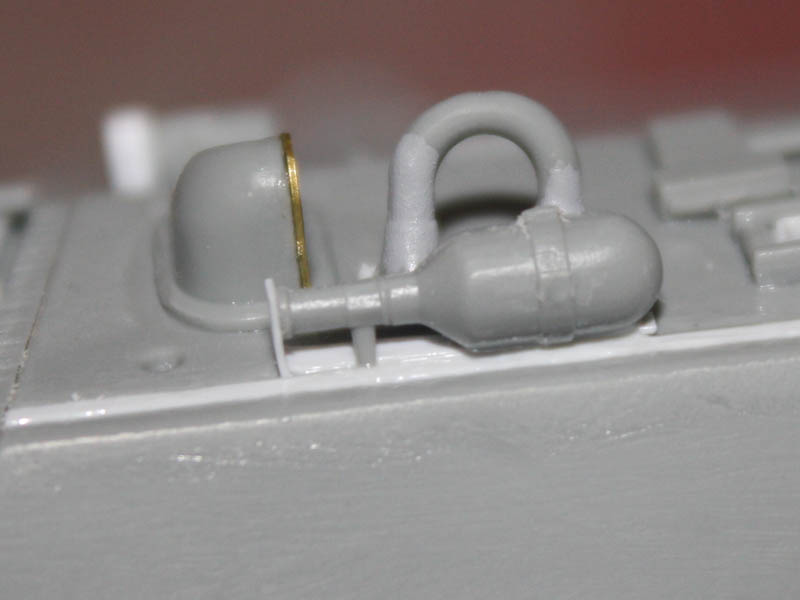
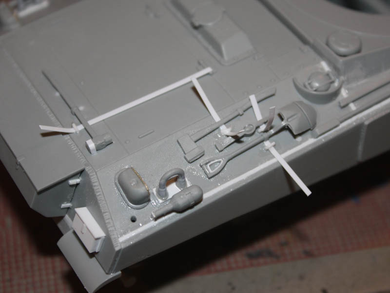
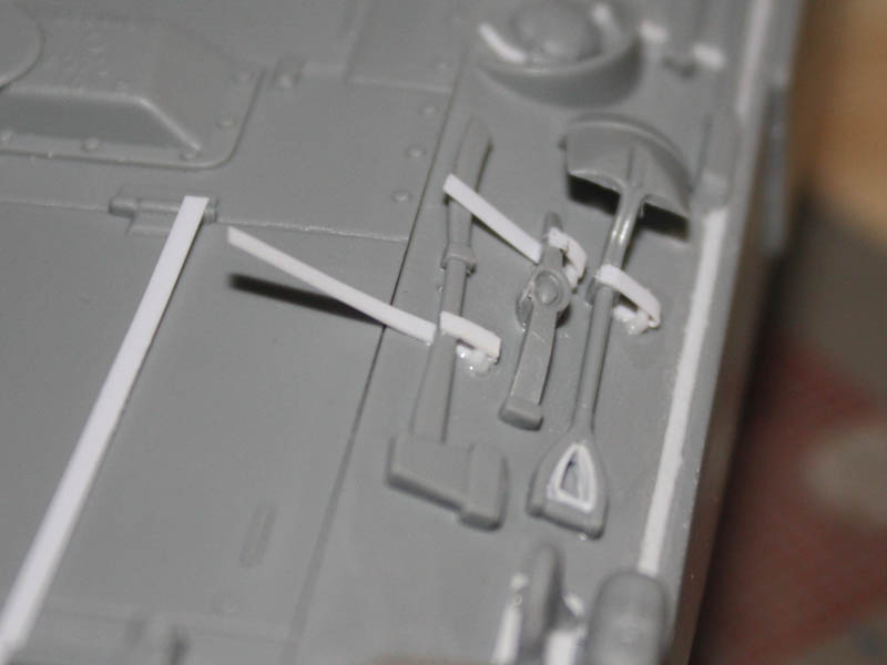
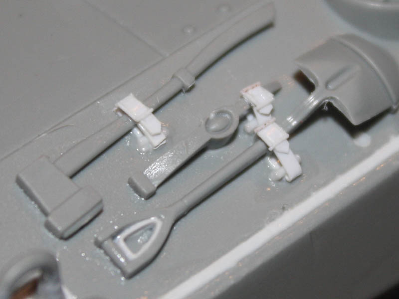
Buckles are a simple box of 0.010 rods glued onto the straps. They dont stand up to microscopic scrutiny, but once painted they look good enough to my Mk.I eyeballs. Adding them is fun I use the glue brush to pick them up, and an Optivisor to see what Im doing
Tom