_GOTOBOTTOM
Armor/AFV: Modern - USA
Modern Armor, AFVs, and Support vehicles.
Hosted by Darren Baker
M966 HMMWV TOW Missile Carrier
sgtsauer
#065
Visit this Community
Missouri, United States
Joined: March 30, 2002
KitMaker: 2,605 posts
Armorama: 1,814 posts
Posted: Sunday, September 16, 2012 - 04:00 PM UTC
I'm building an early US Army M966 TOW Missile system carrier for the 'Tank Destroyer/SPG Campaign'. This image is the inspiration for my kitbash build:


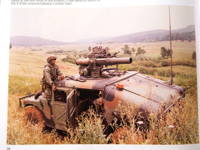
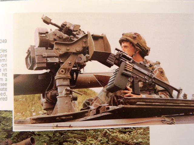
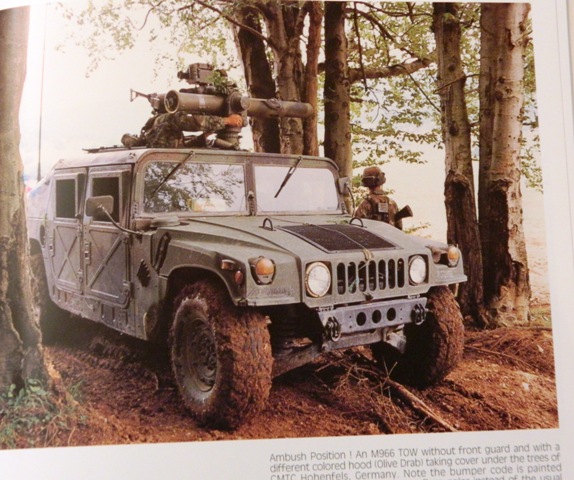
The photo is from Verlinden Productions book Warmachines No. 15 3/325 ABCT Airborne Battalion Combat Team "Blue Falcons" in action.

Several things appeal to me about the vehicle in this image.
1. All green engine hood (bonnet as some call it).
2. Early style side mirrors
3. Early style M249 SAW with 'skeleton' rear stock.
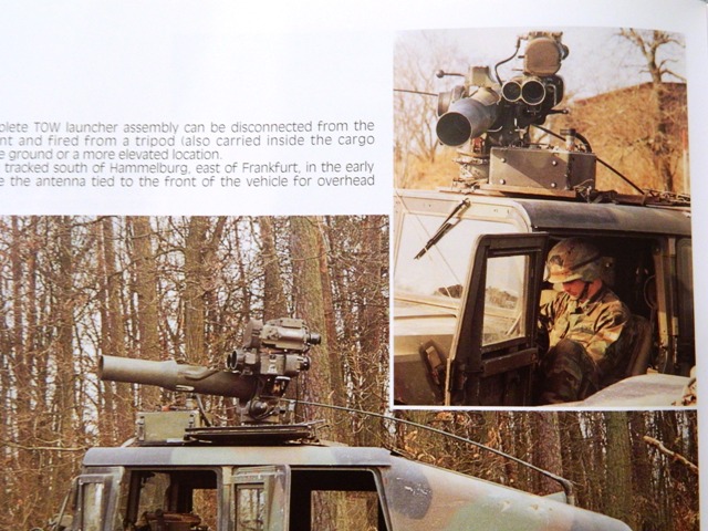
4. Secondary weapon mounted with the TOW system.

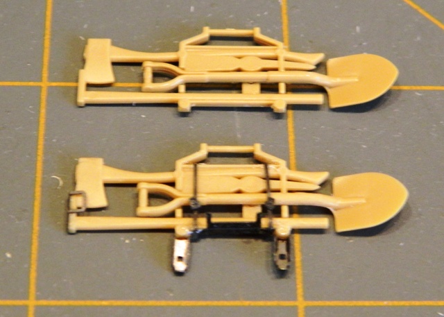
The model build will be a kitbash of the following:
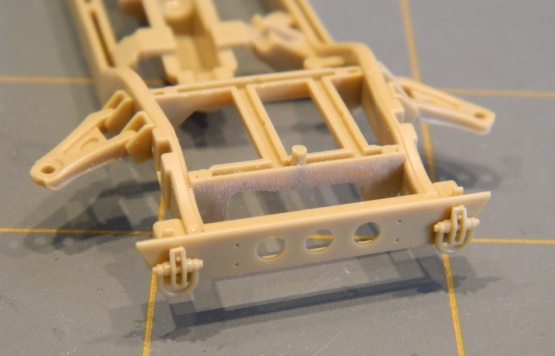
Base kit- Tamiya M1046 TOW Missile Carrier
Parts from-
a. Tamiya M1025 Early Armored Doors
b. M249 from Tamiya Modern U.S. Accessory Set
c. Secondary weapon mount from Academy M1025
d. I'm pondering using an EDUARD M1046 PE Set but am not
sure if I want to go that deep into the project.


I will have some work to do to figure out how to mount the secondary weapon system on the turret ring. Unfortunately, I don't have a completely clear photo of the way it is mounted. The book has a picture of an M60 mounted with TOW system also. I may decide to do that. Not sure yet.
Thatguy
Visit this Community
Virginia, United States
Joined: November 09, 2008
KitMaker: 487 posts
Armorama: 451 posts
Posted: Sunday, September 16, 2012 - 04:22 PM UTC

Quoted Text

I will have some work to do to figure out how to mount the secondary weapon system on the turret ring.


Part 10, or some variation thereof, in the following picture should be able to be mounted when the the TOW system is installed. This might require relocation of the missile guidance set, which looks it might be inside the vehicle from the cable feeding down in the second picture.


These pictures of 3-325th ABCT predate the current setups which are designed to allow for the mounting of a secondary weapon. For those interested, you can see the current secondary weapon mount in the pictures showing the TOW ITAS missile system installation in FM 3-22.32, which is available online.
sgtsauer
#065
Visit this Community
Missouri, United States
Joined: March 30, 2002
KitMaker: 2,605 posts
Armorama: 1,814 posts
Posted: Sunday, September 16, 2012 - 05:14 PM UTC

Quoted Text


Quoted Text

I will have some work to do to figure out how to mount the secondary weapon system on the turret ring.


Part 10, or some variation thereof, in the following picture should be able to be mounted when the the TOW system is installed. This might require relocation of the missile guidance set, which looks it might be inside the vehicle from the cable feeding down in the second picture.


These pictures of 3-325th ABCT predate the current setups which are designed to allow for the mounting of a secondary weapon. For those interested, you can see the current secondary weapon mount in the pictures showing the TOW ITAS missile system installation in FM 3-22.32, which is available online.


Thanks for the great information Joe. You certainly saved me some time in research. I truly appreciate it.
sgtsauer
#065
Visit this Community
Missouri, United States
Joined: March 30, 2002
KitMaker: 2,605 posts
Armorama: 1,814 posts
Posted: Sunday, September 16, 2012 - 05:18 PM UTC
Step 1- Front & Rear Axles


Step 2- Attaching Lower Arms To Front & Rear Axles


sgtsauer
#065
Visit this Community
Missouri, United States
Joined: March 30, 2002
KitMaker: 2,605 posts
Armorama: 1,814 posts
Posted: Sunday, September 16, 2012 - 05:40 PM UTC
Joe, here is a couple of additional images of vehicles from the same unit, but not the same vehicle from my 1st photo.


Do you think that there could be something with the MILES system that eliminates the need for the crew to mount the guidance box? You can see the rack in the photo and it looks like there is space to mount it.

I additionally noted, after reviewing other photos in the book, that there is a different sight system mounted below the night sight when the TOW system is in MILES configuration. When MILES is not installed, the normal sight system is in place below the night sight.


Here is another view of the secondary weapon mount. It almost looks like there is a steel plate that the mount is on. I will look at this closer when I get to the turret construction stage.


I'm hoping I can cobble together the mount from existing kit parts. I don't think the light machine gun mount from an Academy humvee kit is going to be sufficient.
The_musings_of_NBNoG
Visit this Community
Oregon, United States
Joined: January 08, 2012
KitMaker: 520 posts
Armorama: 516 posts
Posted: Sunday, September 16, 2012 - 05:58 PM UTC
check out the mounts from Live Resin...there might be something adaptable there.
Thatguy
Visit this Community
Virginia, United States
Joined: November 09, 2008
KitMaker: 487 posts
Armorama: 451 posts
Posted: Monday, September 17, 2012 - 01:13 AM UTC
Yeah, with those new pictures, it looks like something entirely homebrewed by 3-325th and not what thought at all. Looks like a triangular plate attached to the "rail" part 10 is attached to in the picture I posted and the missile guidance set rack.
sgtsauer
#065
Visit this Community
Missouri, United States
Joined: March 30, 2002
KitMaker: 2,605 posts
Armorama: 1,814 posts
Posted: Monday, September 17, 2012 - 09:37 AM UTC
Step 3: Installation of the transfer case and muffler/exhaust.

Simple step that involves assembling the two halves of the transfer case. When the transfer case is assembled, you install it at the rear of the engine. The last piece installed here is half of the muffler which contains the exhaust pipe section.


17741907
Visit this Community
Istanbul, Turkey / Türkçe
Joined: December 05, 2007
KitMaker: 953 posts
Armorama: 705 posts
Posted: Monday, September 17, 2012 - 10:16 AM UTC
Fine works Brent...Good luck....
bat-213
Visit this Community
Canada
Joined: December 30, 2011
KitMaker: 902 posts
Armorama: 788 posts
Posted: Monday, September 17, 2012 - 10:22 AM UTC
your build is look good,nice work.
sgtsauer
#065
Visit this Community
Missouri, United States
Joined: March 30, 2002
KitMaker: 2,605 posts
Armorama: 1,814 posts
Posted: Monday, September 17, 2012 - 05:57 PM UTC
I have decided to go off the deep end and use Eduard set
35 655 M-1046 Humvee TOW photo-etch set on this build.


You can see photos of all of the content on my website at this link:

HMMWV In Scale Eduard 35 655 M1046 Humvee TOW
kubisz
Visit this Community
Wojewodztwo Slaskie, Poland
Joined: February 18, 2007
KitMaker: 978 posts
Armorama: 977 posts
Posted: Monday, September 17, 2012 - 07:57 PM UTC
Brent, I love these old-type Humvees from late 80s and early 90s Very interesting version You've chosen. I've got this Verlinden's book - great source of simple, but very interesting versions to build.

Good job so far And very good idea to use Eduard's PE set. Waiting to see more
35th-scale
Visit this Community
Kildare, Ireland
Joined: November 21, 2007
KitMaker: 3,212 posts
Armorama: 2,807 posts
Posted: Tuesday, September 18, 2012 - 12:10 AM UTC
Nice to see an old one being built with all new M1114s and M1151 now available.
sgtsauer
#065
Visit this Community
Missouri, United States
Joined: March 30, 2002
KitMaker: 2,605 posts
Armorama: 1,814 posts
Posted: Tuesday, September 18, 2012 - 08:58 AM UTC
I've started using the previously mentioned Eduard set for the M1046 TOW Carrier.

In this photo, you can see the difference in details between the 'out-of-box' pioneer tool rack and a tool rack with details from the Eduard set. My intent is to display this pioneer rack in the lowered position but still on the vehicle.


The design of the Eduard set is partially incorrect in that the locking brackets aren't angled correctly as they are on the real vehicle. See image of the real assembly here:
HMMWV Pioneer Tools and Rack

Additionally the photo-etch straps that go over the tools should go between the mattock handle and the carrier frame. But, as a result of the way the kit part was molded, you have no choice but to glue the PE strap on the outside of the frame. I hope that makes sense.
sgtsauer
#065
Visit this Community
Missouri, United States
Joined: March 30, 2002
KitMaker: 2,605 posts
Armorama: 1,814 posts
Posted: Tuesday, September 18, 2012 - 09:56 AM UTC
I'm skipping around the construction sequence some to facilitate airbrushing the vehicle chassis.

With that in mind, here is completed Step 5 which has you assembling the pioneer tool rack and the fuel tank.


Here is completed step 8 which is the rear bumber and the front bumper.

Rear bumper (shown with added Eduard details):


Front bumper:


Although the Tamiya M1046 TOW Carrier kit does have the parts for the standard front bumper, it does not have the directions for it in the kit instructions. I had to reference a set of the instructions for the Tamiya M1025 Armament Carrier to make sure I got the assembly correct.
amoz02t
#192
Visit this Community
Kentucky, United States
Joined: November 25, 2009
KitMaker: 1,383 posts
Armorama: 1,281 posts
Posted: Tuesday, September 18, 2012 - 10:44 AM UTC
Looking really good here Brent! Thanks for sharing and keep up the great work
sgtsauer
#065
Visit this Community
Missouri, United States
Joined: March 30, 2002
KitMaker: 2,605 posts
Armorama: 1,814 posts
Posted: Tuesday, September 18, 2012 - 05:26 PM UTC
Well, I figured since I was doing some multi kit part combining, adding photo-etch and doing a little scratch building I might as well use one of my DEF Model resin tire sets. So, I have spent some time tonight shooting lots of photos of the tire set before assembling all of them.

Here is the packaging:


Here are the 5 tires....you will notice that 2 ea are labeled 'A' and 2 ea are labeled 'B' and 1 ea is labeled 'S' (spare).


Here is a photo of the DEF Model tire(left) next to the Tamiya tire (right).


Here is a photo of a real tire for tread comparison.


Here is an image of one of the assembled DEF Model wheels next to one of the assembled Tamiya wheels.


If you look close, you will see there is a bit of gap between the wheel and tire of the DEF Model wheel assembly compared to the tight fit of the Tamiya parts. I think once the DEF Model tire/wheel is painted, the gap won't be noticeable.

For those interested, I have 14 images of the DEF Model set posted here:

DEF Model DW 35004 HMMWV R/T II Sagged Wheel Set

I have a few photos of the real Goodyear Wrangler R/T II posted here:

Goodyear Wrangler R/T II Photos
Boris1991
Visit this Community
Zuid-Holland, Netherlands
Joined: October 13, 2009
KitMaker: 307 posts
Armorama: 278 posts
Posted: Tuesday, September 18, 2012 - 11:47 PM UTC
Nice build so far?
those TOW Missile launcher are brutal to see on a M966!.
planning on building a small diorama? like the picture from you book?
sgtsauer
#065
Visit this Community
Missouri, United States
Joined: March 30, 2002
KitMaker: 2,605 posts
Armorama: 1,814 posts
Posted: Wednesday, September 19, 2012 - 03:24 AM UTC
Thanks for the compliment Boris. At this time, I don't have any intent to build a vignette or diorama for the vehicle.
Chilihead
Visit this Community
Missouri, United States
Joined: July 03, 2002
KitMaker: 626 posts
Armorama: 456 posts
Posted: Wednesday, September 19, 2012 - 05:17 AM UTC
Brent
Sweet!
Drop me a line when you have time.
Mrosko
sgtsauer
#065
Visit this Community
Missouri, United States
Joined: March 30, 2002
KitMaker: 2,605 posts
Armorama: 1,814 posts
Posted: Wednesday, September 19, 2012 - 05:03 PM UTC
I got the DEF Model wheels assembled, part gaps filled and cleaned up.

This photo shows the gaps between the tire and wheel/rims filled using Mr. Surfacer 500.


This photo shows the tire assemblies after the seams and Mr. Surfacer 500 have been cleaned up.


The wheels should look pretty good after being painted and dry brushed.
sgtsauer
#065
Visit this Community
Missouri, United States
Joined: March 30, 2002
KitMaker: 2,605 posts
Armorama: 1,814 posts
Posted: Sunday, September 23, 2012 - 05:54 AM UTC
The following photos are a combination of steps 4 through 8.


The photo below shows the 'top' of the frame/chassis. I didn't paint it as thoroughly since the body of the HMMWV will block it from view.


Herchealer
Visit this Community
Indiana, United States
Joined: July 31, 2003
KitMaker: 1,523 posts
Armorama: 710 posts
Posted: Sunday, September 23, 2012 - 05:09 PM UTC
Slacker! No cutting corners!


Looks good bro!

Herky
sgtsauer
#065
Visit this Community
Missouri, United States
Joined: March 30, 2002
KitMaker: 2,605 posts
Armorama: 1,814 posts
Posted: Sunday, September 30, 2012 - 03:31 AM UTC
Here is the end result of kit steps 1-10. Remember I have added some PE and Def Model wheels.


The tires were painted with Life Color 'Tire Black' to give some contrast between the wheel color and the tire even though in real life there isn't a big scale color difference. For some reason the color photographs lighter than it actually appears.

 _GOTOTOP