After providing the in box review for Armorama on this kit and pointing out the issues with the kit, I felt it would be a good idea to do a build log on this kit to point out in my own way how to correct the kit's two most glaring inaccuracies - the undersized road wheels and the height of the lower hull. The kit will build into either the ISU-152-1 with the BL-8 gun, or the ISU-152-2 with the BL-10 gun. I will be building the ISU-152-2 since it's the only sprue that is added in from the older Cyber-Hobby ISU-152 "3 n 1" kit from the early 2000s. Additionally, this build will be somewhat of a quick build, as we don't have much in the way of markings (ZERO, actually) and a single color scheme (4BO) with very little in the way of weathering, etc.
The kit itself is reviewed here and covers the basic kit. I won't go into the details, but will dive right into the kit.
The first step of the instructions starts off, of course, with the running gear. Return rollers, idlers and drive sprockets are all two piece affairs with no photo etch at all. The road wheels, all 14 of them are again two piece assemblies and is the first (and major) part of the kit that needs attention. The road wheels of the IS-1/IS-2 (and by extension the ISU-122/152 family) are 550mm in diameter. This equates to roughly 15.71mm in 1/35 scale. DML kits, no matter the date, are all undersized by approximately .86mm. To correct this, it has been suggested on many sites to use strip styrene to fix this. I found that Evergreen #124 (.020" x .080") is a good match to increase the diameter to bring it more in line with the correct 15.71mm.
Through trial and error and the use of a draftsman's template I found that a 1 7/8" strip was the exact outside diameter of the road wheel so I commenced to cutting them using "The Chopper", an invaluable tool in my little workbench arsenal.
The following shots show the basic flow from stock, to added strip, to a 4BO painted road wheel.
The wheel width is just a hair more than the .020" width of the styrene strips. I tried to remedy this by using Tenax 7R as my cement of choice and slightly pressing down to get some melted plastic squeezed out to the edges. A quick pass with a Flexi File and that seemed to do the trick.
This is the most time consuming part of the build, as you have 14 wheels, each with an inner and outer wheel, so you'll be cutting, gluing, squeezing and filing 28 of these guys. I suggest a good movie playing in the background or some music to while away the time.
The other thing I was thinking of is that you're increasing the OUTER diameter to match the factory specification, but you're not decreasing the INNER diameter to match. Granted, you are building a model of a prototype weapon that never reached production (or the battlefield) prior to the end of the war, but it's something to keep in mind.
Also, I would suggest building them all up, then giving them a good once over and pick your better of the two sides to show off. The road wheel hubcaps are separate affairs (Part B6) so if you make a minor goof on the strip addition, you can simply turn that wheel half to the inside of the lower hull and call it good.
Our next step will involve getting the lower hull suspension installed and fixing the lower hull height.
Hosted by Jacques Duquette
Dragon 6796 ISU-152-2 Build Log
BigSmitty
Minnesota, United States
Joined: October 01, 2008
KitMaker: 597 posts
Armorama: 439 posts
Joined: October 01, 2008
KitMaker: 597 posts
Armorama: 439 posts
Posted: Wednesday, December 17, 2014 - 10:36 AM UTC
pgb3476
Texas, United States
Joined: March 11, 2007
KitMaker: 977 posts
Armorama: 976 posts
Joined: March 11, 2007
KitMaker: 977 posts
Armorama: 976 posts
Posted: Wednesday, December 17, 2014 - 07:33 PM UTC
Nice approach on fixing the road wheels.
BigSmitty
Minnesota, United States
Joined: October 01, 2008
KitMaker: 597 posts
Armorama: 439 posts
Joined: October 01, 2008
KitMaker: 597 posts
Armorama: 439 posts
Posted: Wednesday, December 17, 2014 - 07:56 PM UTC
Thanks Greg. Wish I could take credit for it, but found it through a translated Russian page. They basically broke down every manufacturer's kits and road wheel dimensions for the IS-1/IS-2 kits; since this was basically a re-issue of #6052 I knew the kit size. Once I knew how much I needed to increase the diameter, it was just a matter of getting the right thickness strip. I'm about 0.14mm too big, but that's only 4.9mm on a 1/1 scale so I will go with it.
pgb3476
Texas, United States
Joined: March 11, 2007
KitMaker: 977 posts
Armorama: 976 posts
Joined: March 11, 2007
KitMaker: 977 posts
Armorama: 976 posts
Posted: Thursday, December 18, 2014 - 12:58 AM UTC
Are you also going to correct the hull/chassi height issue too?
BigSmitty
Minnesota, United States
Joined: October 01, 2008
KitMaker: 597 posts
Armorama: 439 posts
Joined: October 01, 2008
KitMaker: 597 posts
Armorama: 439 posts
Posted: Thursday, December 18, 2014 - 05:50 AM UTC
That is the plan, Greg. I will probably build the kit per the instructions (upper and lower hull separate) then before I join them I'll do the surgery to correct the 1.5mm height loss.
BigSmitty
Minnesota, United States
Joined: October 01, 2008
KitMaker: 597 posts
Armorama: 439 posts
Joined: October 01, 2008
KitMaker: 597 posts
Armorama: 439 posts
Posted: Thursday, December 18, 2014 - 08:11 PM UTC
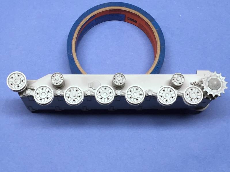
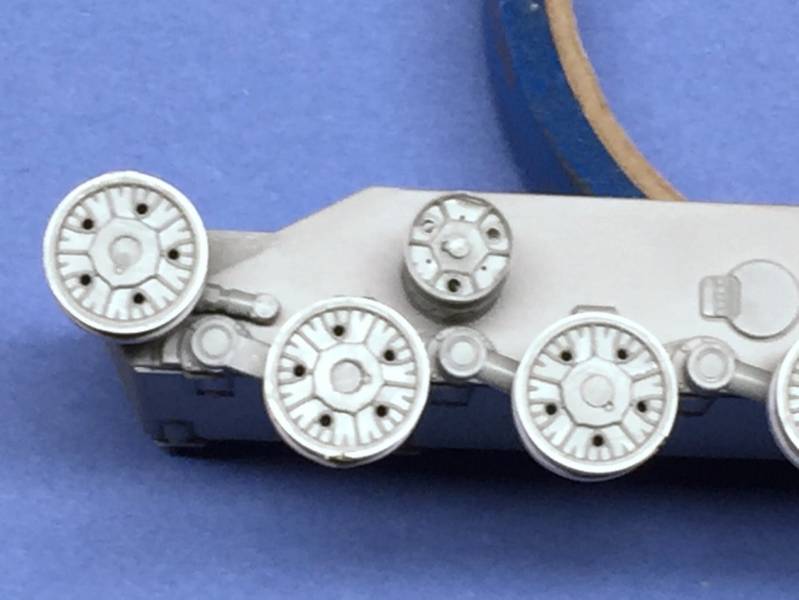
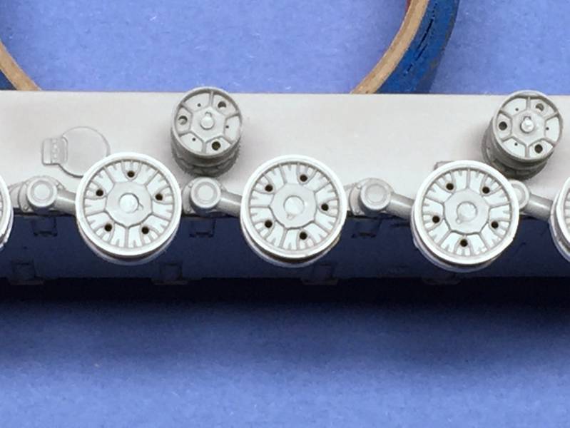
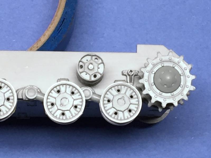
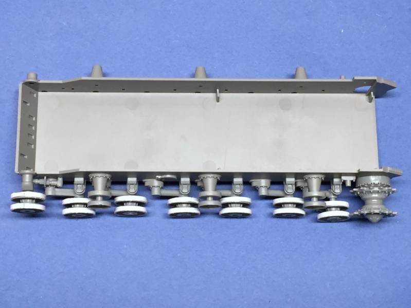
First half of Step 2 in the directions is now complete, although the wheels and drive sprocket will not be glued in place until the very end of the build:
I would caution anyone building this kit that the small parts called out have the typical "Dragon arrows" pointing them out; that is you have four or five parts being called out (in the case of the front-most road wheel) and all the arrows point in the same direction. For the second road wheel (the first along the bottom of the hull) the suspension arm (B31) is FLAT, not rounded like the other five arms (B6). Some of the smaller parts had a large amount of flash around the mounting pins and almost every road wheel needed a round file passed through it to fit the suspension arm. In no means a deal breaker, but for those of you who've build an older Dragon "Imperial Series" it's about that same quality. Most of the sprue runners actually have the old "Shangai Dragon" logo before it became DML.
More photos of the progress...keep in mind the wheels with the added strip still need some cleanup, and I'll be filling in a couple of spots that won't be hidden when the wheel comes in contact with the track. Also, each of the road wheels and return rollers have center caps, but they are paper thin and have sprue connection points at an angle on the visible side. So they'll need to be taken off with extreme care.
Next up is the other side of the suspension then onto adding the 1.5mm strips to the lower hull to get the height right.
As always, thanks for looking and any comments are most welcome!
Jacques
Minnesota, United States
Joined: March 04, 2003
KitMaker: 4,630 posts
Armorama: 4,498 posts
Joined: March 04, 2003
KitMaker: 4,630 posts
Armorama: 4,498 posts
Posted: Friday, December 19, 2014 - 03:15 AM UTC
BigSmitty? Really? Nice work so far man.
BigSmitty
Minnesota, United States
Joined: October 01, 2008
KitMaker: 597 posts
Armorama: 439 posts
Joined: October 01, 2008
KitMaker: 597 posts
Armorama: 439 posts
Posted: Friday, December 19, 2014 - 04:27 AM UTC
Quoted Text
BigSmitty? Really? Nice work so far man.
Yes, it is true, good sir. I have gone to the 4BO side. Kyle would be so proud.
uarkram
Pennsylvania, United States
Joined: July 19, 2014
KitMaker: 22 posts
Armorama: 19 posts
Joined: July 19, 2014
KitMaker: 22 posts
Armorama: 19 posts
Posted: Friday, December 19, 2014 - 05:29 AM UTC
Hey Big Smitty,
Got a question for you. How is it that squids are treadheads? Shouldn't we be building battleships or something?
Just wondering.
IT2(SW)
1993-2003
'Armor' Mark Rau
(The nickname came from the guys in my club)
Got a question for you. How is it that squids are treadheads? Shouldn't we be building battleships or something?
Just wondering.
IT2(SW)
1993-2003
'Armor' Mark Rau
(The nickname came from the guys in my club)
BigSmitty
Minnesota, United States
Joined: October 01, 2008
KitMaker: 597 posts
Armorama: 439 posts
Joined: October 01, 2008
KitMaker: 597 posts
Armorama: 439 posts
Posted: Friday, December 19, 2014 - 08:32 AM UTC
Mark
I spent enough time bobbing around on those tin cans that if I ever got a kit of anything I served on I would go bonkers trying to fix the inaccuracies. So I model armor and claim ignorance. It really annoys the true tread heads in my club, including a certain forum moderator here.
uarkram
Pennsylvania, United States
Joined: July 19, 2014
KitMaker: 22 posts
Armorama: 19 posts
Joined: July 19, 2014
KitMaker: 22 posts
Armorama: 19 posts
Posted: Friday, December 19, 2014 - 08:49 AM UTC
I was on carriers, so I know what you mean.
Am following your build with great intrest 'cause i don't know that much about russian armor. Am going to take what you have shown here, and apply it to my old DML 122/152.
BigSmitty
Minnesota, United States
Joined: October 01, 2008
KitMaker: 597 posts
Armorama: 439 posts
Joined: October 01, 2008
KitMaker: 597 posts
Armorama: 439 posts
Posted: Friday, December 19, 2014 - 08:50 PM UTC
Mark
What is the kit # of your 122/152? Some of the DML kits have a retooled lower hull that fixed the height issue. Unfortunately, none of the JS-1/JS-2 family (including SU/ISU 122-152s) every had the wheel issue fixed.
C_JACQUEMONT
Loire-Atlantique, France
Joined: October 09, 2004
KitMaker: 2,433 posts
Armorama: 2,325 posts
Joined: October 09, 2004
KitMaker: 2,433 posts
Armorama: 2,325 posts
Posted: Saturday, December 20, 2014 - 05:05 AM UTC
Quoted Text
Mark
What is the kit # of your 122/152? Some of the DML kits have a retooled lower hull that fixed the height issue.
AFAIK the ones that were corrected in this area were the one written about in this thread plus the JSU-152 "3 in 1" Orange Box from CyberHobby (ref 9112) and the JS2-JS1 "2 in 1"Orange Box from CyberHobby (ref 9108).
Cheers,
Christophe
BigSmitty
Minnesota, United States
Joined: October 01, 2008
KitMaker: 597 posts
Armorama: 439 posts
Joined: October 01, 2008
KitMaker: 597 posts
Armorama: 439 posts
Posted: Saturday, December 20, 2014 - 06:29 AM UTC
Quoted Text
Quoted TextMark
What is the kit # of your 122/152? Some of the DML kits have a retooled lower hull that fixed the height issue.
AFAIK the ones that were corrected in this area were the one written about in this thread plus the JSU-152 "3 in 1" Orange Box from CyberHobby (ref 9112) and the JS2-JS1 "2 in 1"Orange Box from CyberHobby (ref 9108).
Cheers,
Christophe
Christophe
Thanks for the CH ref 9108 as having the correct hull also; I looked through several resources and only found 9112 as having the correct lower hull. Cheers!
BigSmitty
Minnesota, United States
Joined: October 01, 2008
KitMaker: 597 posts
Armorama: 439 posts
Joined: October 01, 2008
KitMaker: 597 posts
Armorama: 439 posts
Posted: Wednesday, December 24, 2014 - 12:08 AM UTC
An update for 12/24:
Finished up Step 2 of the instructions, which is the suspension and lower hull. Of note is the six rectangular slots that need to be opened up on the front of the lower hull, as these are for the spare track link brackets which were fitted to the prototype unit. Also, if you are planning on dry fitting the drive sprockets for the tracks (to take off the entire assembly after curing for painting/weathering/etc) then I would recommend leaving off part B29 on both sides, as it would be a tough fit to get the drive sprockets back on with it in place. The road wheels are in two parts, and have some flash in the center where the suspension arm runs through. I took a small round file and cleared them out to allow me to fit them to the arms with little trouble.
The road wheel and return roller caps were molded with very thick sprue attachment points, so take care when removing them. I cut close to the sprue tree itself, which allowed me to angle in with my cutter to get a closer final cut. The caps are paper thin, you can see right through them when you hold them up to a light, so take care when doing your cleanup.
Some photos of the running gear in place (dry fit for now).
Step 3 involves cleaning up and making two sets of 88 Magic Tracks. The instructions give a good indication of how they are to be oriented, and you will be using two parts (one with guide horns, one without) in an alternating fashion. The upper run has a bit of natural sag, and this is why I'm planning on keeping the drive sprocket and front road wheel dry fit so I can pull the entire assembly off.
Step 4 deals exclusively with the upper hull, engine deck, and other "topside" parts. A word of caution here - parts D7 and D8 are reversed in the directions. I found out the hard way, but have altered them to match the photos I've seen of the 152-2. The fuel cans on each side are shaped correctly but each end cap is slightly undersized, which will need some attention. The two hatches on top are split, which allows them to be shown open, but with a completely barren interior, I felt it best to close them up. To fit properly, you'll need to spend a few minutes cleaning up the flash, and trimming down the hinges on each piece of the hatch (Parts D4 and D5 respectively).
That is currently where the build stands. My upper hull is warped (as shown below) so I'll have to figure out how to straighten that out as well. I will say that some of the pieces in Step 4 are much better molded than others. Next up is getting the hull height corrected and filling in the sponsons, which are wide open.
As always, thanks for looking and comments are always welcome.
Jacques
Minnesota, United States
Joined: March 04, 2003
KitMaker: 4,630 posts
Armorama: 4,498 posts
Joined: March 04, 2003
KitMaker: 4,630 posts
Armorama: 4,498 posts
Posted: Wednesday, December 24, 2014 - 03:46 AM UTC
Matt, you are NOT annoying to this treadhead at all. I suppose my extensive knowledge of floating targets can be annoying to you squids though...
looks like a good build. Keep at it. Do you think you will need counterweight in the rear to keep it from nose diving?
BigSmitty
Minnesota, United States
Joined: October 01, 2008
KitMaker: 597 posts
Armorama: 439 posts
Joined: October 01, 2008
KitMaker: 597 posts
Armorama: 439 posts
Posted: Wednesday, December 24, 2014 - 06:35 AM UTC
Quoted Text
Matt, you are NOT annoying to this treadhead at all. I suppose my extensive knowledge of floating targets can be annoying to you squids though...
looks like a good build. Keep at it. Do you think you will need counterweight in the rear to keep it from nose diving?
Ha ha! I don't think I'll need to add anything to the rear as the barrel isn't metal, it's a two piece plastic job that doesn't weigh a heck of a lot. I'll be testing that theory later though, as I see how much it tilts when not attached to the lower hull...
Oh and Jacques... you should see some of the stuff on my "next up" pile... Trumpeter's BTR-50, Meng's Tiger (the Russian HMWWV knock off) and a Hobby Boss T-28... The horror!
BigSmitty
Minnesota, United States
Joined: October 01, 2008
KitMaker: 597 posts
Armorama: 439 posts
Joined: October 01, 2008
KitMaker: 597 posts
Armorama: 439 posts
Posted: Saturday, December 27, 2014 - 07:43 AM UTC
Progress so far:
Steps 4 and 5 completed - These two steps encompass the bulk of the kit parts with the entire upper hull being completed. Leave off part A3 as it is the ISU-152 gun travel lock which was not fitted to either of the 152-1 or 152-2 prototypes based on references.
Another odd thing was the lower hull itself. I was preparing to add in the 1.5mm to get the correct height (20mm) when I decided to measure myself as it looked when dry fit that the sponsons were high enough. This lower hull (Part X) is the correct lower hull. You can tell if the lower hull has a large gap when fit together (similar to the Tamiya Sherman sponsons, if anyone knows what I'm talking about). I measured it out... 20.12mm, which in 1:1 scale is just over 700mm from lower hull to the bottom of the sponson. So no surgery needed on this kit, very similar to the JSU-152 "3 in 1" Orange Box release 9112, which has the same corrected hull.
Step 6 involves removing a small portion of the front of the barrel to replicate the shorter barrel of the BL-10 main gun. The instructions are 1:1 scale for this step, so it's an easy and quick step.
Step 7 is the main gun assembly. Use Part E1 for the ISU-152-2, and Parts E5, E6, E7 and E8 as well; the directions are flipped for E1 or C2.
Step 8 is attaching the main gun to the casemate. Do not use part A9 (front brace) for the ISU-152-2 as it was not used.
The final step is attaching the upper hull to the lower hull and adding in the spare tracks. As I have seen photos with and without them (ISU-152-1 and ISU-152-2 from the lower front, without distinguishing between them) I took the artistic license to NOT add them in.
Here are my latest photos of the build:
gastec
Auckland, New Zealand
Joined: February 03, 2014
KitMaker: 1,042 posts
Armorama: 871 posts
Joined: February 03, 2014
KitMaker: 1,042 posts
Armorama: 871 posts
Posted: Saturday, December 27, 2014 - 08:00 AM UTC
Man, that is a huge gun Wouldn't want to be on the receiving end
Bet the tank was a real b*tch to steer though with all that weight up front!
Gary
Bet the tank was a real b*tch to steer though with all that weight up front!
Gary
Jacques
Minnesota, United States
Joined: March 04, 2003
KitMaker: 4,630 posts
Armorama: 4,498 posts
Joined: March 04, 2003
KitMaker: 4,630 posts
Armorama: 4,498 posts
Posted: Sunday, December 28, 2014 - 12:26 AM UTC
Just to be clear, Part A3, the gun travel lock, was NEVER used on any of the SU or ISU vehicles...unless they had the super secret, never photographed, rubber barrel.
Looks like a good beastie.
BigSmitty
Minnesota, United States
Joined: October 01, 2008
KitMaker: 597 posts
Armorama: 439 posts
Joined: October 01, 2008
KitMaker: 597 posts
Armorama: 439 posts
Posted: Sunday, December 28, 2014 - 07:03 PM UTC
I should have mentioned that the A3 travel lock was left over from using a JS-1/JS-2 hull, as Jacques pointed out. At any rate, we've now got some 4BO and the road wheels attached at this point, and one set of tracks (88 links per side).
On target for a finish prior to 1/1/15...
BigSmitty
Minnesota, United States
Joined: October 01, 2008
KitMaker: 597 posts
Armorama: 439 posts
Joined: October 01, 2008
KitMaker: 597 posts
Armorama: 439 posts
Posted: Tuesday, December 30, 2014 - 08:52 AM UTC
The build as it stands is finished. Tracks are on, some dusting with the airbrush (it WAS only a prototype) and a flat coat. I hit some of the upper areas with a little Russian Green to lighten up the 4BO primary color. Hard to see even with the white balance corrected for my camera.
If I were to go for any aftermarket parts for this I would probably spring for any Fruils that might fit the hull (IS-1/IS-2 or ISU-152 series) as the kit Magic Tracks were a beast to keep together for some reason. First set I've ever had that fought me literally every single of the 88 links per side. Other than that and the age of the molds (lots of flash to clean up) the kit was quite enjoyable.