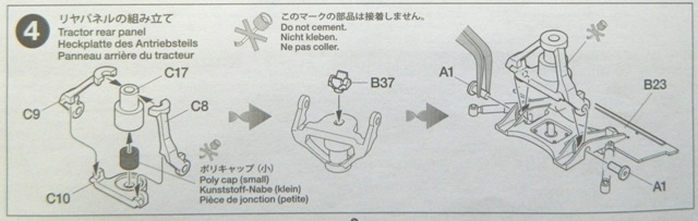
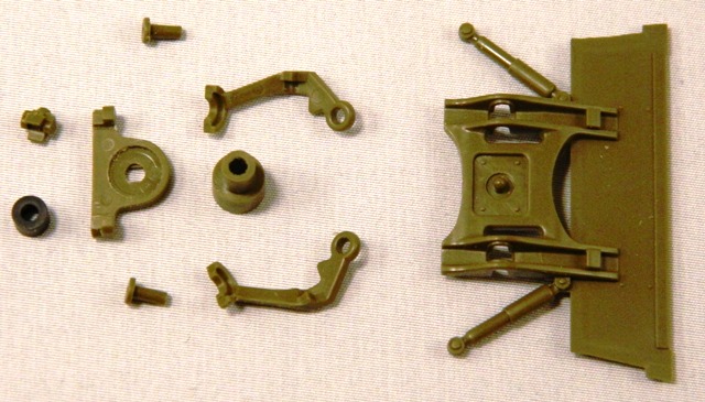
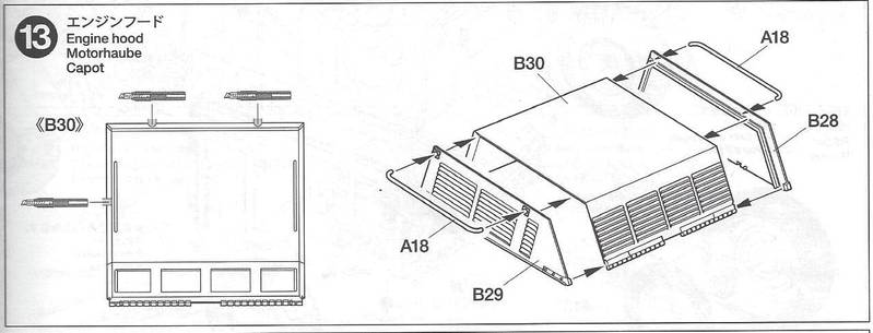
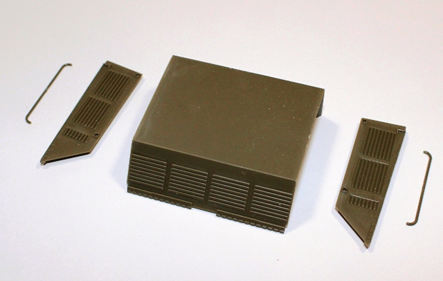
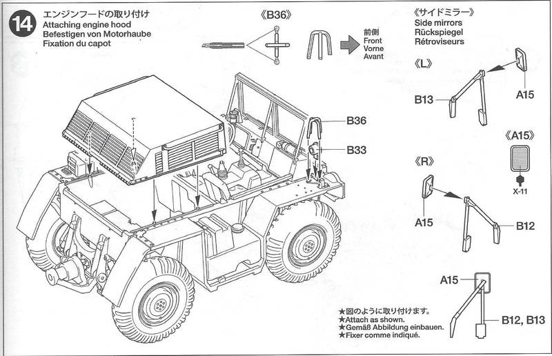
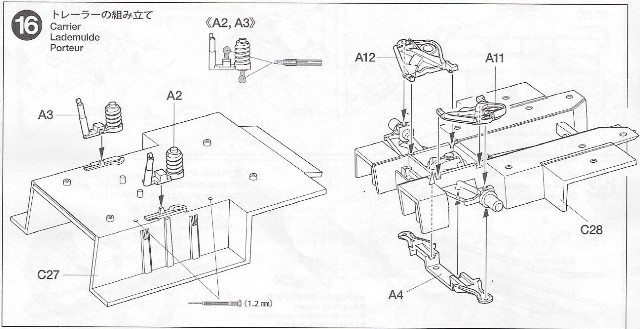
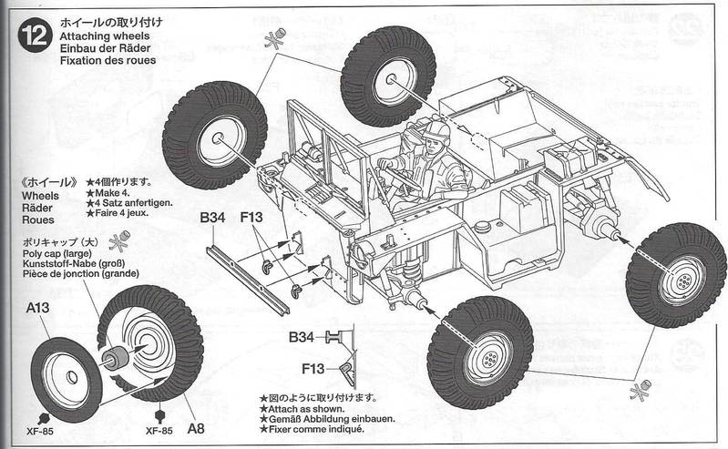
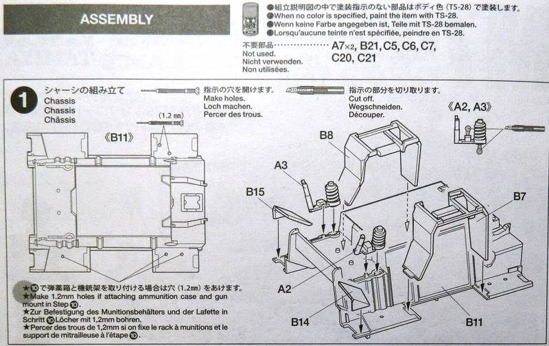
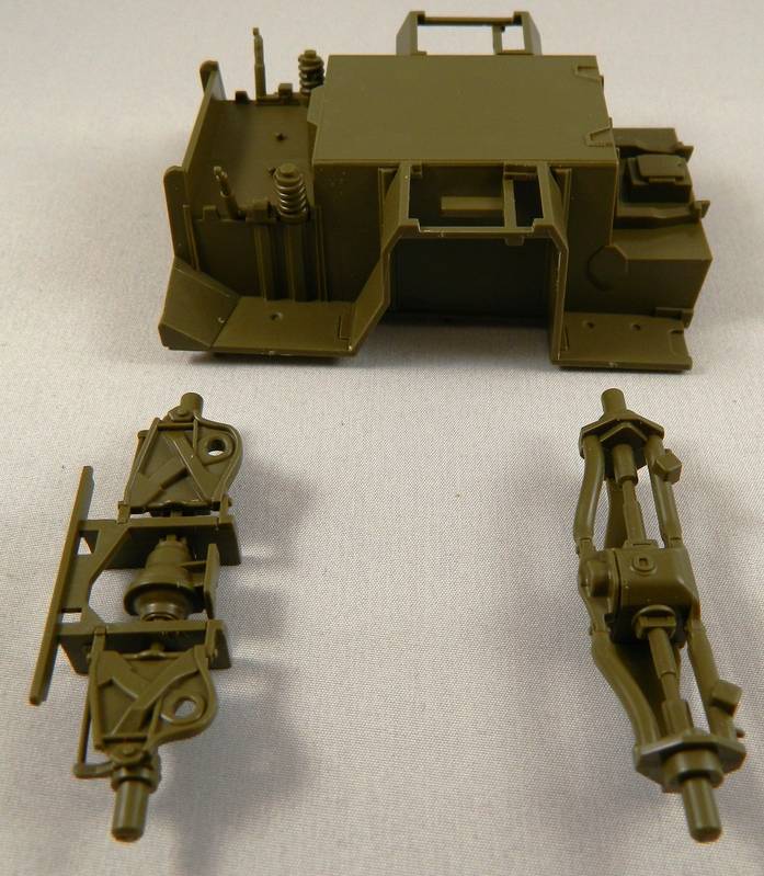
Step 12
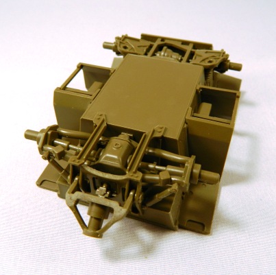
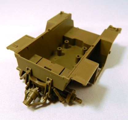
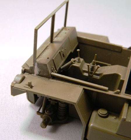
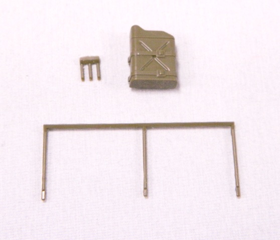
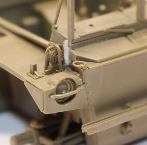
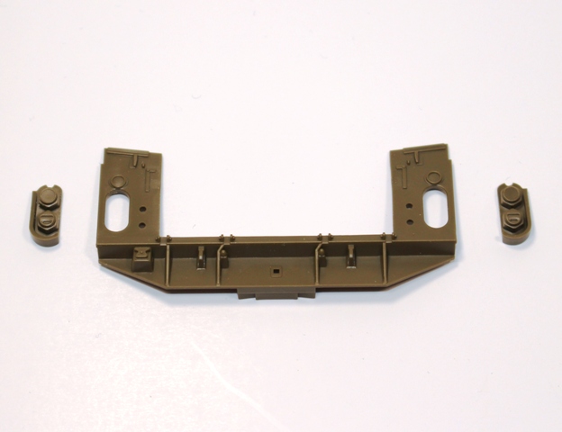
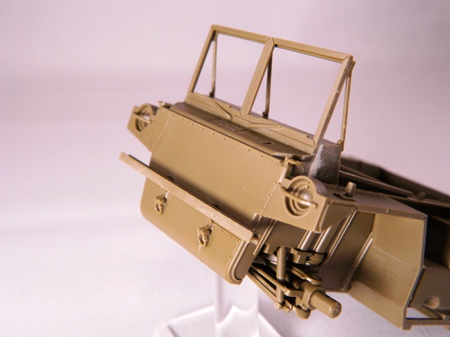
In this step we are assembling the wheels (A8,A13,polycap), installing the front tie-downs (F13) and the front bumper (B34).
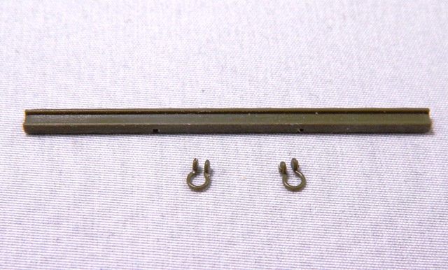
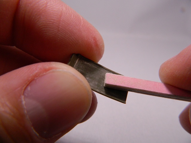
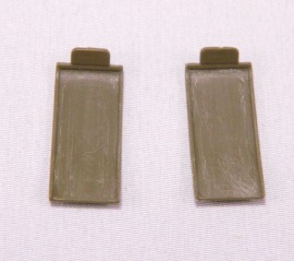
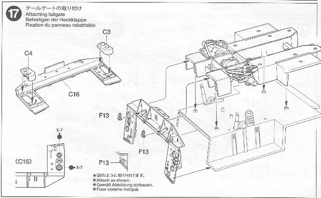
Parts F13 are extremely fragile. There are four in the kit (2 ea for the front, 2 ea for the rear). I completely broke two of the parts trying to clean them up. I have sent an email to Tamiya USA asking to buy a sprue F to replace my two broken parts.
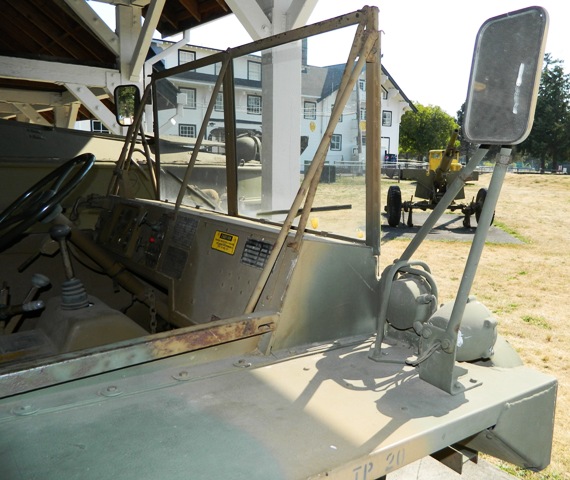
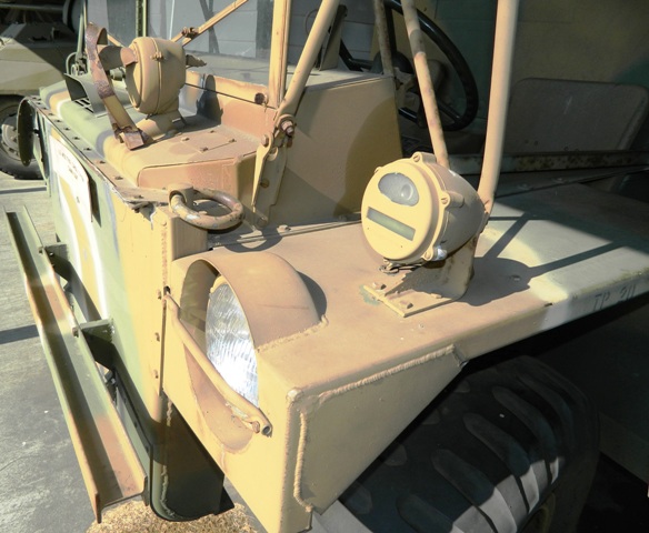
The instructions put emphasis on installing parts F13 at an angle up against the vehicle body. I questioned this as the tie-down eyes usually hang in a vertical position. After reviewing several pictures of operational Gama Goats, I did not see a single vehicle where parts F13 where not angled back against the vehicle body.
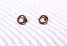
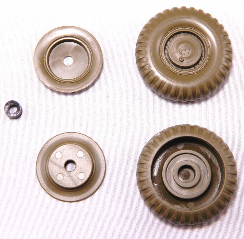
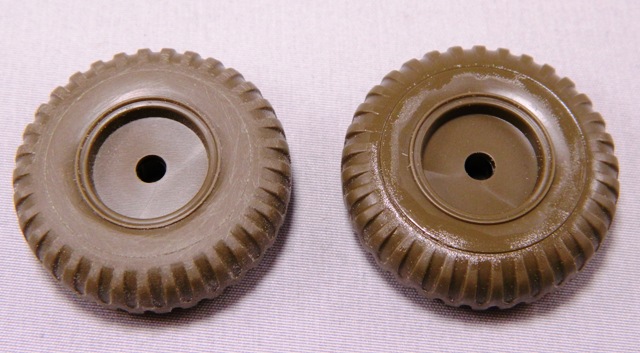
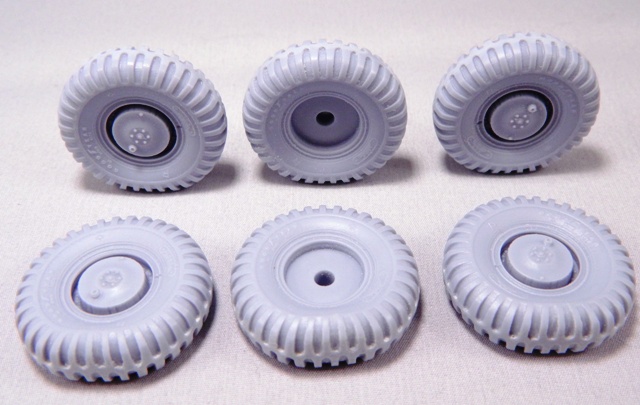
The rest of the step is devoted to the vehicle wheels. Here is a brief look at the wheels provided in the kit. Since I'm not using the kit wheels, I only assembled two of them for display purposes here on this blog.
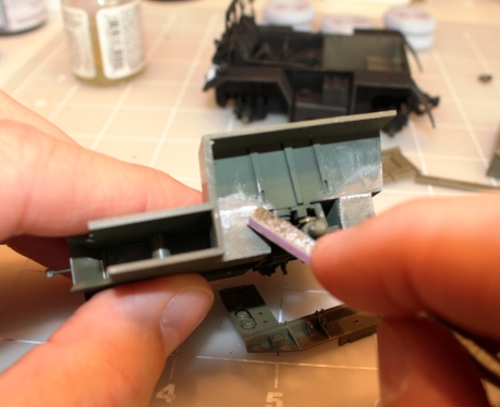
In this photo you see the seam on the back side of the wheel from assembling the parts. The wheel on the right has had liquid glue applied only. The wheel on the left has been glued and sanded to remove the seam.
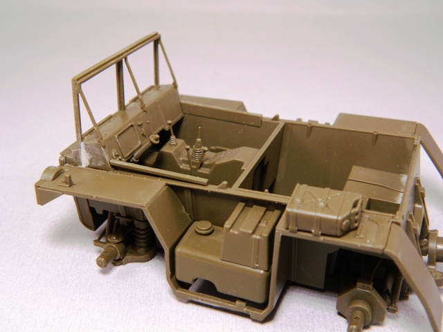
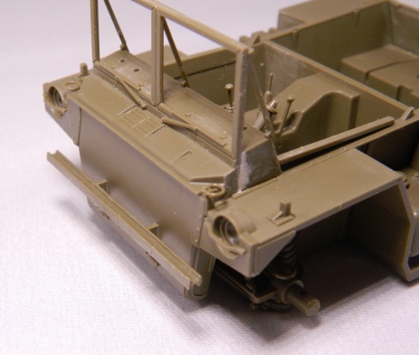
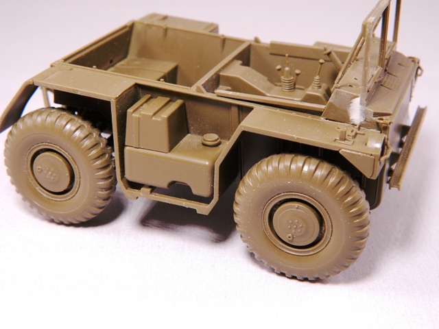
Here is how the tractor looks with the kit wheels installed.
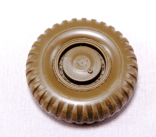
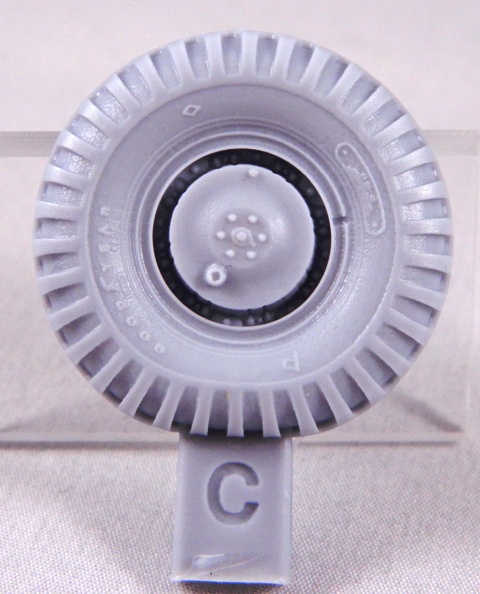
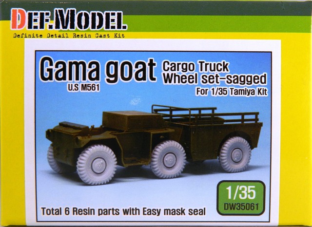
I am using a set of Def Model Gama Goat resin replacement wheels.
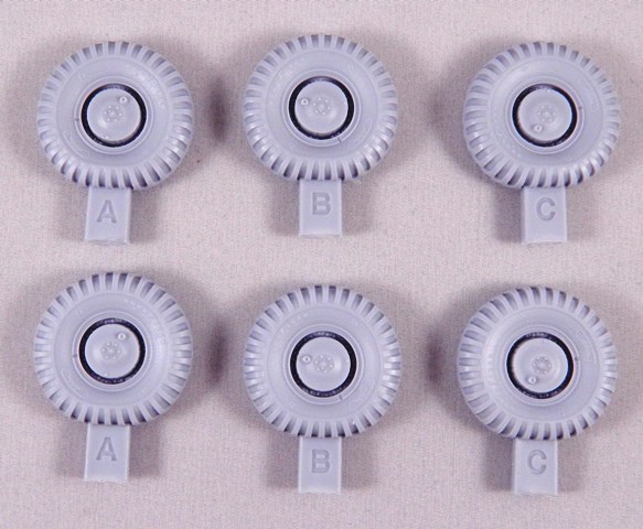
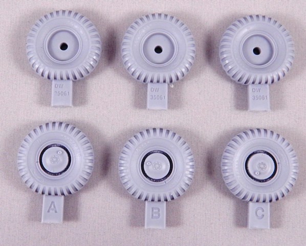
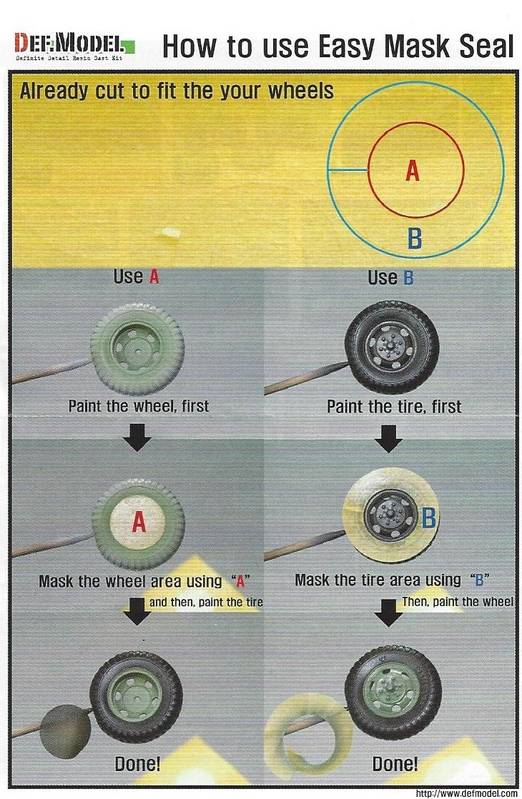
The wheels are cast in light resin and come with a set of wheel masks and mask instructions. The resin pour plugs are attached to flat part of these "weighted" tires.

The wheel mask instructions are a generic set of instructions.
Front of resin wheel. Note the tire face details/lettering..this is not on the kit tires.
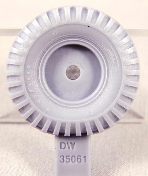
Rear of resin wheel. Note again the tire face detail/lettering that is not present on the kit tires.
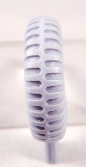
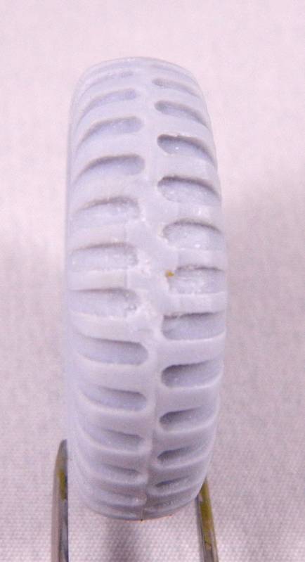
Tire tread detail..
Here is the wheel after cutting off the pour plug.
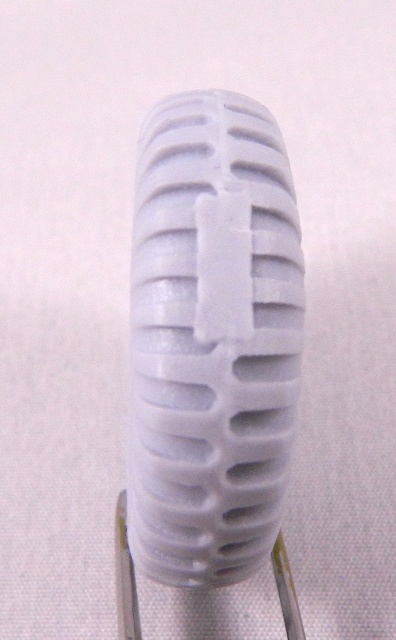
In this photo, I have sanded down the remainder of the pour plug and used a dremel tool to reestablish tire tread where the pour plug was attached.
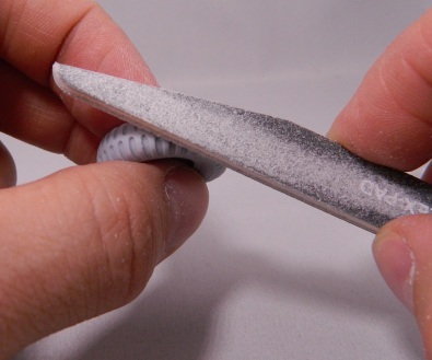
The resin tires had a faint mold seam that ran around the tire. I sanded this mold seam off with a sanding stick.
Here is the final dressed up tires with pour plugs removed and tire treads recreated in the flat "weighted" area of each tire.
Here is a tire tread comparison.
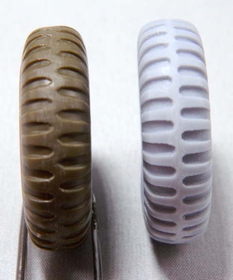
Overall tire comparison images.
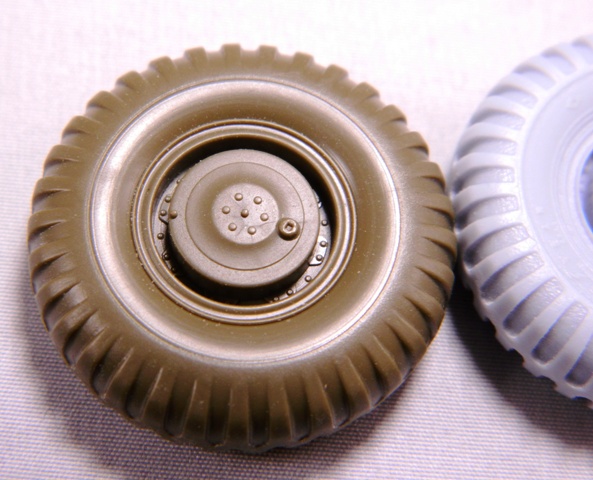
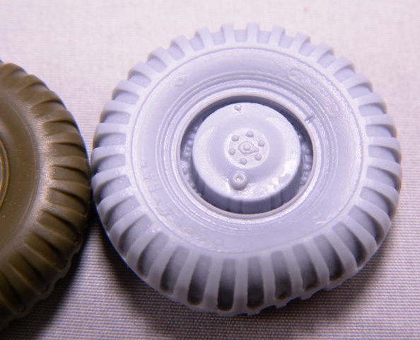
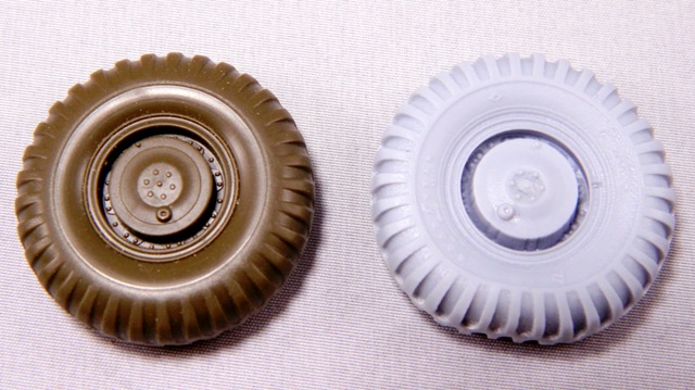
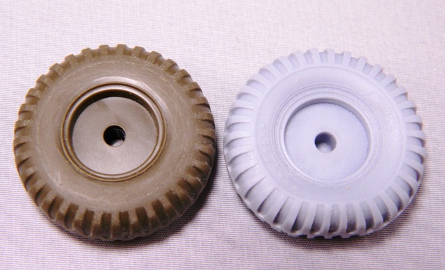
Image showing the tractor with one of each tire on for appearance comparison
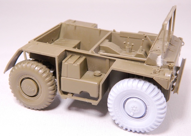
Image showing the tractor with all resin tires on for appearance comparison.
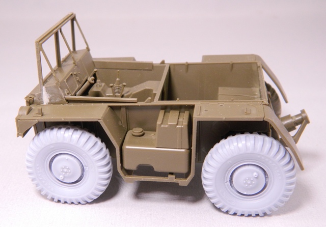
Image showing the tractor with kit wheels again.


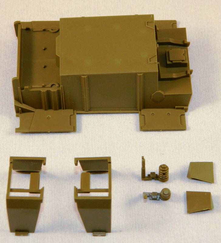
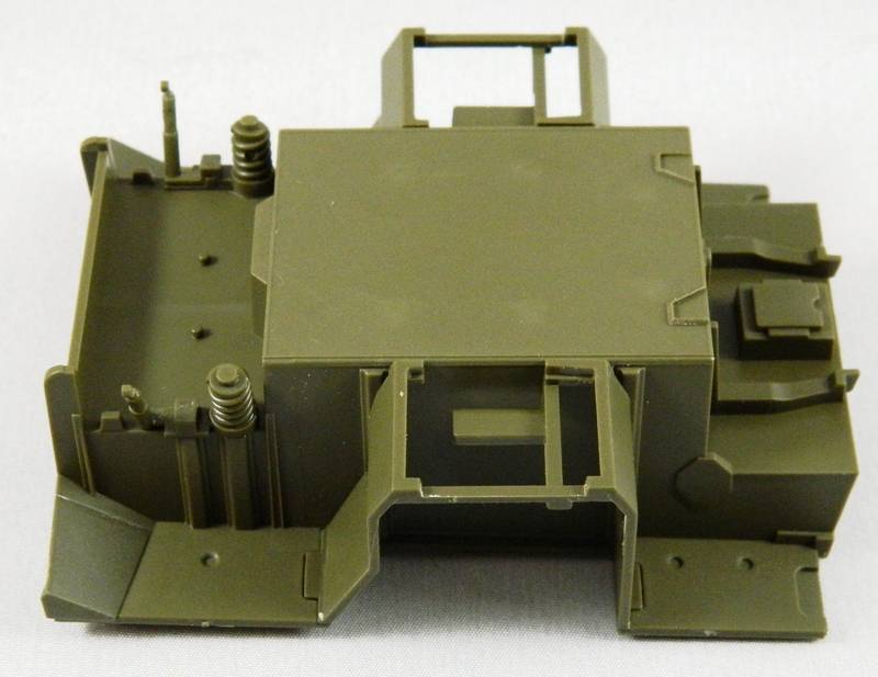


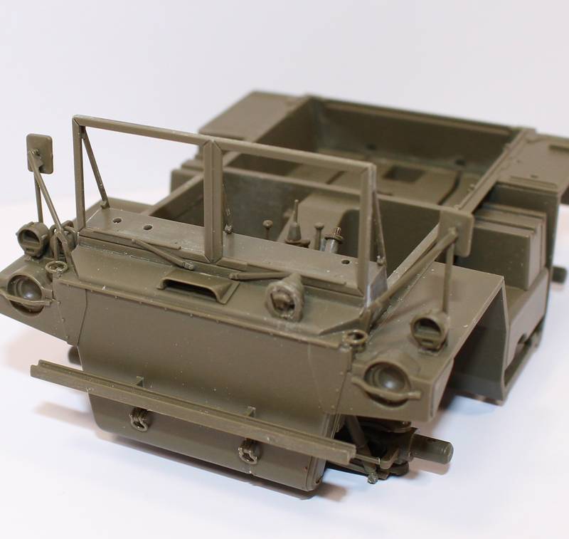
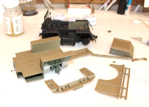
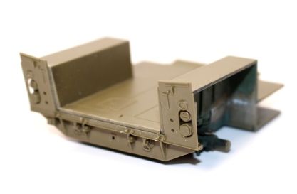
 Look at those nice fine parts! Working on my Panda and I forgot how beautiful the Tamiya kits are.