Tim,
when the engine was parked outside (as was mostly common in Russia as most sheds were destroyed) (it was called "Kalt stehen - standing cold") the chimney would be covered, the ash pan was closed, the cabin doors closed and all valves to the cylinders shut. The engine could then rest for a prolongued perior under hot steam without freezing. The water in the tank was heated by steam, no electricity involved, this would reduce the time it could rest, though.
Steam would push into the tank and heat it. Water was sucked into the injectors to feed the boiler by steam also with the help of underinflation/negative pressure due to the steam flow through a valve.
In short the advanced frost protection included: double cabin walls, chimney covers, heated cabin floor, glass wool or similar material for insulation of the water tank, cylinders, steam and water pipes, especially the feed water pipes running along the left-hand side of the engine), the Knorr Pump's top section and general insulation of pipes. Also, you will notice that around the Knorr pump, on many engines there were pipes outside and around it. They were all/most placed below the boiler cover for frost protection. Later engines had them hidden in general.
Hosted by Darren Baker
BR 52 Kriegsdampflokomotive 1/35 Scratched

Blaubar

Joined: December 15, 2016
KitMaker: 261 posts
Armorama: 246 posts

Posted: Tuesday, January 17, 2017 - 03:23 PM UTC
Dioramartin

Joined: May 04, 2016
KitMaker: 1,476 posts
Armorama: 1,463 posts

Posted: Tuesday, January 17, 2017 - 03:57 PM UTC
Aha! My late Dad was a Professor of mechanical engineering (gas turbines), you'd think more would have rubbed off! OK so it all basically extended how long it could stand still in sub-zero. I was thinking there might have been some battery or diesel powered engine/generator to speed up a completely cold start. Thanks for the lesson mate, on with the show.


Blaubar

Joined: December 15, 2016
KitMaker: 261 posts
Armorama: 246 posts

Posted: Tuesday, January 17, 2017 - 08:44 PM UTC
Tim,
Jain - a German "yesno". This would have been too costly and too prone to breakdown. The 52 was a design to minimize input and maximize efficiency. Also materials for batteries were needed elsewhere. Stuff was scarce. Diesel was also way too scarce. It took about 8 hrs to heat the engine and get it running from a cold start if I remember it correctly. It took much longer with the mediocre Ukrainian and Russian coal, which had to be sprinkled with Diesel according to literature.
To the left of the Knorr pump there is a "spring steel" pipe sticking out. This is a steam pipe from within the boiler to feed the compressor and the pump. It is covered with some extra copper sheeting in my model as it was back then covered with some thin metal plating. You can see it run along an edge angle to the steam dome cover.
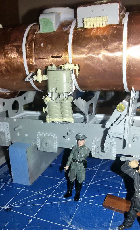
and
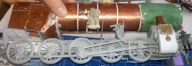
This was not only to keep it warm when standing still but also when running. The immense cold led to 70%+ breakdowns of engines during the Transportkrise (transportation crisis) and in 1941/42.
Russian pipes and grease pumps used thicker diameters and thus did not clog as fast as minimalized german ones! Also did the wheels and running gear overheat and bend due to no greasing and render them useless...
cheers,
/Stefan
Jain - a German "yesno". This would have been too costly and too prone to breakdown. The 52 was a design to minimize input and maximize efficiency. Also materials for batteries were needed elsewhere. Stuff was scarce. Diesel was also way too scarce. It took about 8 hrs to heat the engine and get it running from a cold start if I remember it correctly. It took much longer with the mediocre Ukrainian and Russian coal, which had to be sprinkled with Diesel according to literature.
To the left of the Knorr pump there is a "spring steel" pipe sticking out. This is a steam pipe from within the boiler to feed the compressor and the pump. It is covered with some extra copper sheeting in my model as it was back then covered with some thin metal plating. You can see it run along an edge angle to the steam dome cover.

and

This was not only to keep it warm when standing still but also when running. The immense cold led to 70%+ breakdowns of engines during the Transportkrise (transportation crisis) and in 1941/42.
Russian pipes and grease pumps used thicker diameters and thus did not clog as fast as minimalized german ones! Also did the wheels and running gear overheat and bend due to no greasing and render them useless...
cheers,
/Stefan
Posted: Tuesday, January 17, 2017 - 09:21 PM UTC
Quoted Text
... minimalized German ones!
...
I have heard a saying, attributed to a German marine engineer - If it did not break - it was overbuilt


Blaubar

Joined: December 15, 2016
KitMaker: 261 posts
Armorama: 246 posts

Posted: Tuesday, January 17, 2017 - 11:28 PM UTC
Quoted Text
Quoted Text... minimalized German ones!
...
I have heard a saying, attributed to a German marine engineer - If it did not break - it was overbuilt
Porsche, if I remember correctly, said that if a race car does not break down behind the finish line, resources were ewasted.^^
In some senses it is true, but then again they designed the Maus^^

Blaubar

Joined: December 15, 2016
KitMaker: 261 posts
Armorama: 246 posts

Posted: Thursday, March 02, 2017 - 05:53 PM UTC
Good day,
Does anyone have an idea where I could get custom markings/decals printed? It would be nice to have someone with a decent suggestion. As Archer are doing some nice ones, do they have such a service?
Thanks for your help.
/Stefan
Does anyone have an idea where I could get custom markings/decals printed? It would be nice to have someone with a decent suggestion. As Archer are doing some nice ones, do they have such a service?
Thanks for your help.
/Stefan

Blaubar

Joined: December 15, 2016
KitMaker: 261 posts
Armorama: 246 posts

Posted: Sunday, March 05, 2017 - 09:40 PM UTC
Good evening together,
While I am still interested in custom decals, I redesigned the whole boiler support frame and drafted it on paper. I will use the top of the top part which I left intact and add the rest below.
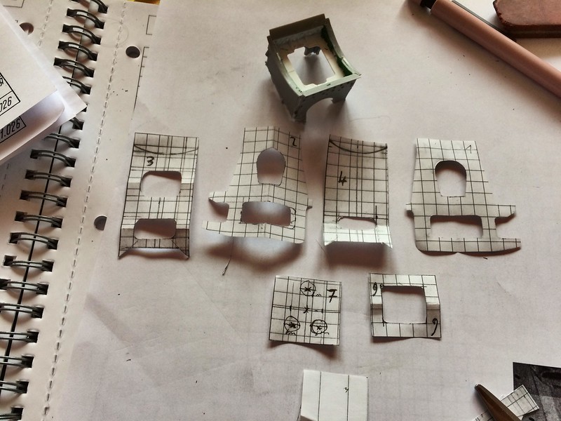
The frame is now separated in two parts. Too many things are off and I will rebuild most of the whole front from scratch and with quite major modifications.
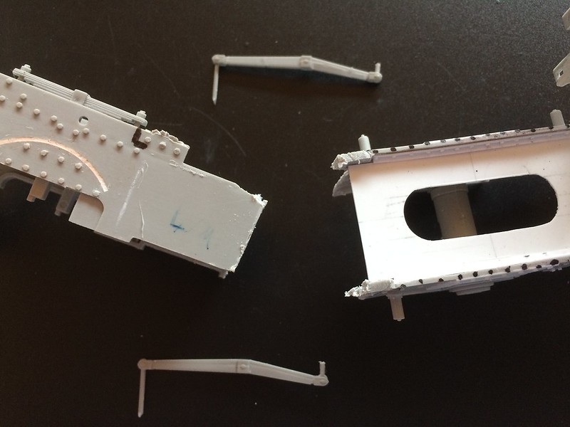
I am drawing and cutting the whole interior front parts as of now and within the next few days before the NC World Cup finale here, I might be able to get an update out. There will be quite a lot of moving and turning parts, as the spring system, which allows the frontal axle to move left/right, is quite crazy.
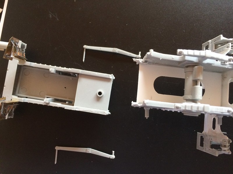
Cheers from snowy Germany,
/Stefan
While I am still interested in custom decals, I redesigned the whole boiler support frame and drafted it on paper. I will use the top of the top part which I left intact and add the rest below.

The frame is now separated in two parts. Too many things are off and I will rebuild most of the whole front from scratch and with quite major modifications.

I am drawing and cutting the whole interior front parts as of now and within the next few days before the NC World Cup finale here, I might be able to get an update out. There will be quite a lot of moving and turning parts, as the spring system, which allows the frontal axle to move left/right, is quite crazy.

Cheers from snowy Germany,
/Stefan

Blaubar

Joined: December 15, 2016
KitMaker: 261 posts
Armorama: 246 posts

Posted: Sunday, March 12, 2017 - 03:03 PM UTC
Good day, fellow plastic modellers,
after last weeks' adjustments the new parts look like this:
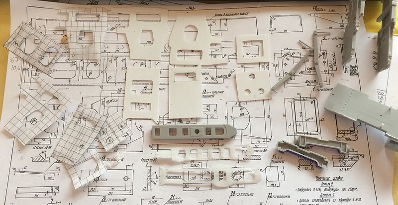
The basic steering rack to the right (need to cut that one again, as I used too thin plastic and it looks awful - compare the shape and the location of the sparrings of Trumpeter^^). Still lots to do, according to the manual some 90 pieces are still needed for the steering rack.
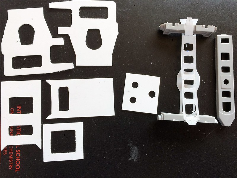
It will kind of look like this in the end- mind however that the whole top and more intermediate layers need to be added:
Now that the frame is cut, I started with the front design. I drew and cut out two .4mm sheets of styrene and then glued them on top of .4mm again. I roughly need about a .75mm thickness for the frame. (as stability will be an issue, I made it marginally thicker). These new parts are 8.5cm long and will fit 2.6cm in front of the centre of the first drive wheel axle. Why these measures? Because at 2.6cm in front the axle, the cylinder support frame will cover the cut in the frame and it is easier to hide the slashed stuff
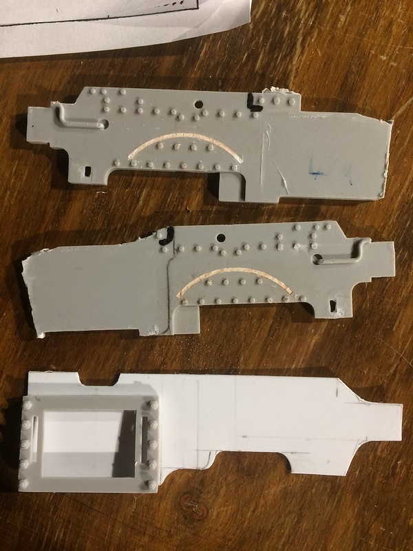
These are the 4 new basic frame parts. You will notice that the cylinder access holes are different in the boiler support and the frame. This is to save steel with the boiler support I assume and as such the hole is bigger here. The height is identical, it is just quite a bit wider.
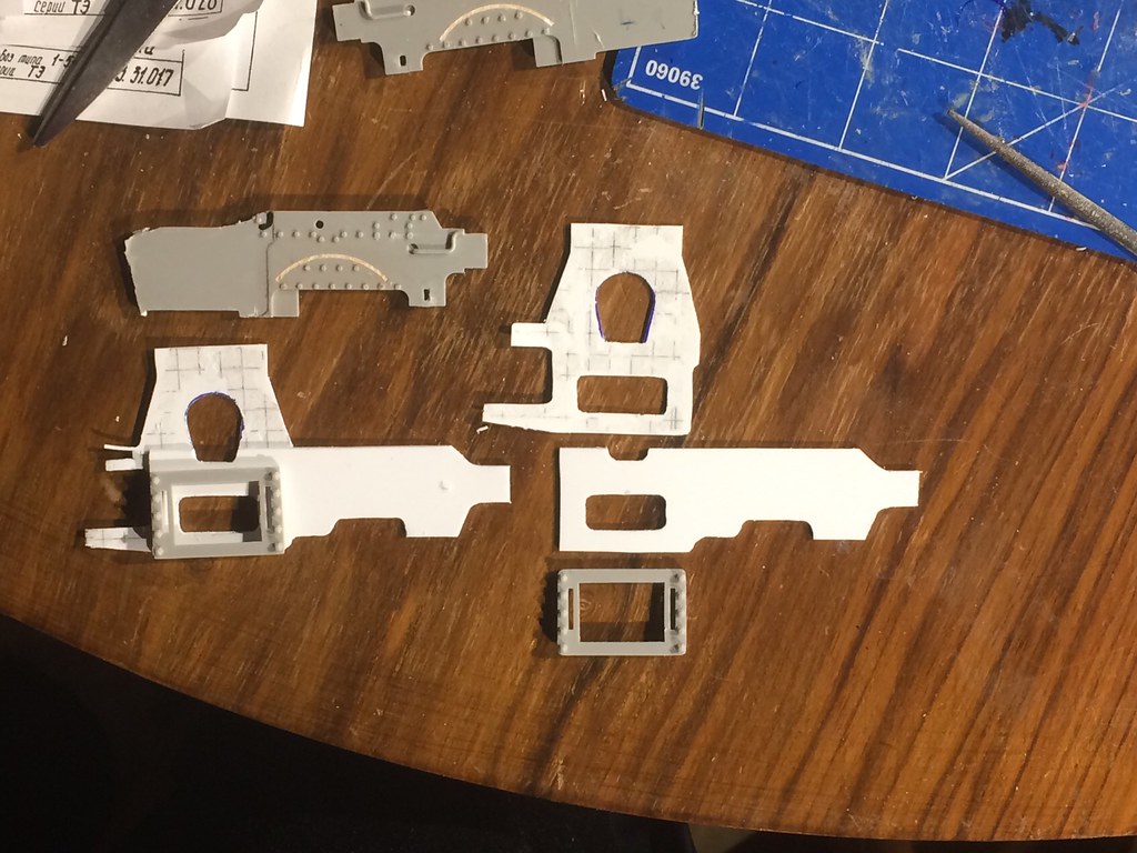
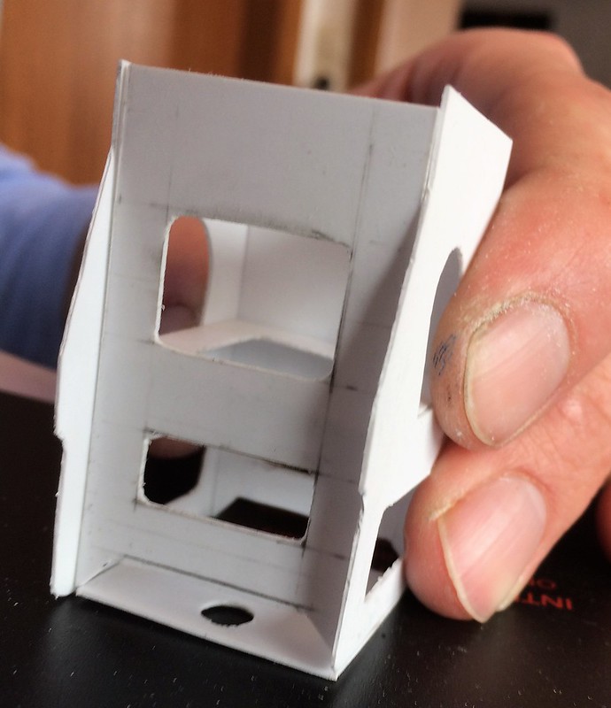
Holding the parts in place to have a look at the new design. I am fairly happy with the result. I need to prepare the frame to glue all these parts to it, however I need to fix the steering stuff first.
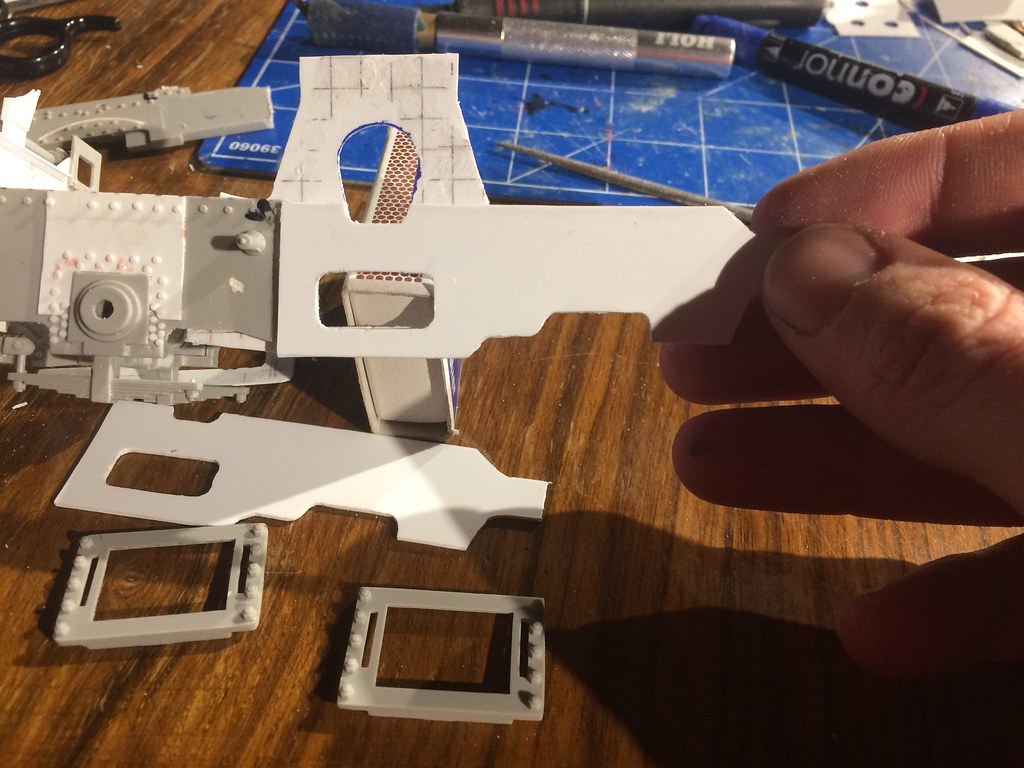
I have then begun a minor assembly of the parts. They are glued with just a bit, so I can still rearrange it if needed, but all angles and alignments seem just right.
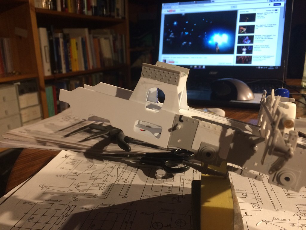
The superheated steam will run through pipes here down into the cylinders and after usage, it will exit the cylinders through the lower gap in the frame into the smoke box...
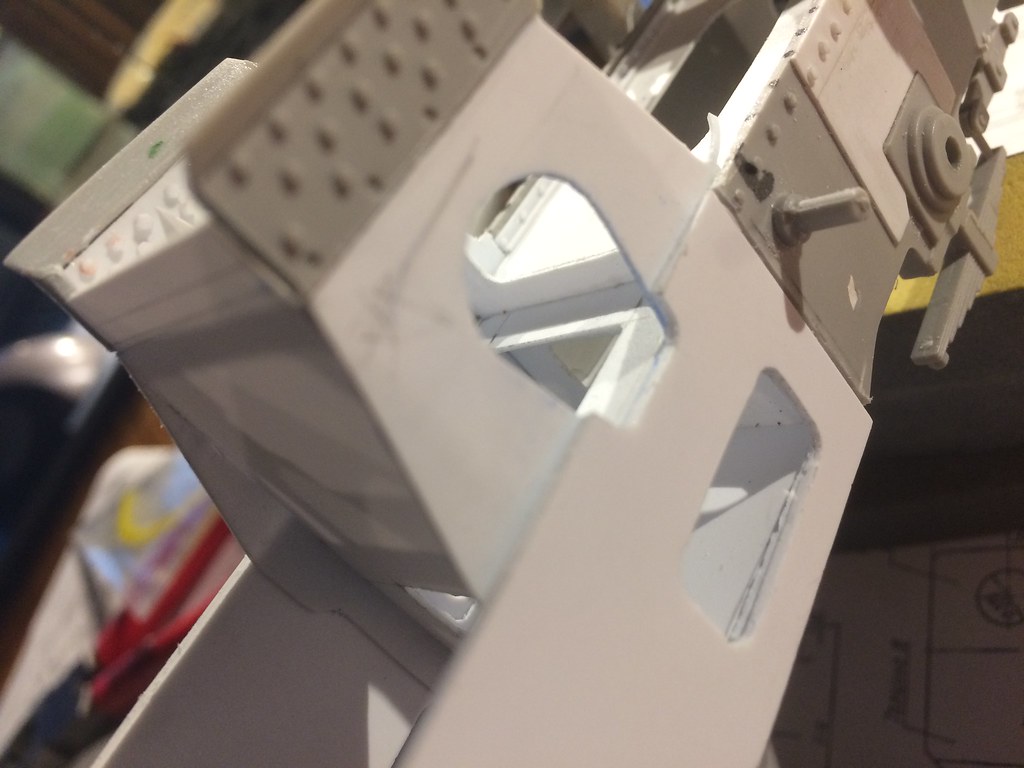
The view from the rear to the front. angles and rivets will get rid of the small gap between the frame and the boiler support (if any of it is left once I glue it in place in a few weeks or months)
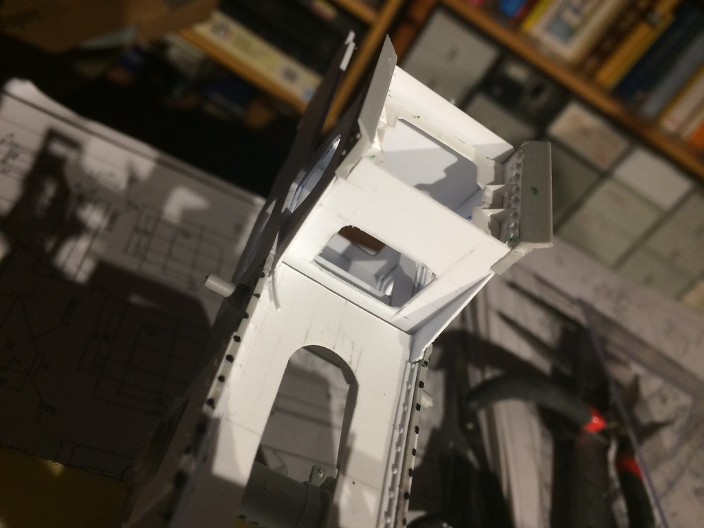
And this is what it will look like with the boiler... I need to trim the intermediate boiler support beams, as their shape is not adjusted to the boiler yet.
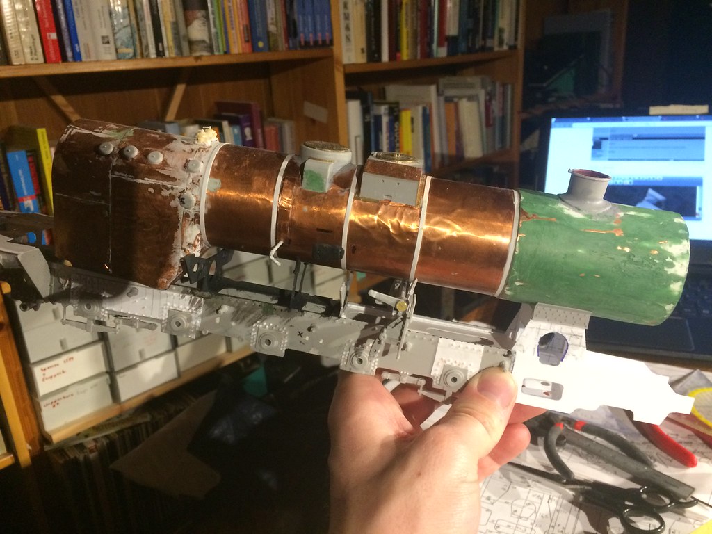
After all, not sure what you think of the project and the build, but I tend to be fairly happy with its progress. I need to buy more and better tools for the next loco build for sure, my current ones are too bad.
Prost,
/Stefan
after last weeks' adjustments the new parts look like this:

The basic steering rack to the right (need to cut that one again, as I used too thin plastic and it looks awful - compare the shape and the location of the sparrings of Trumpeter^^). Still lots to do, according to the manual some 90 pieces are still needed for the steering rack.

It will kind of look like this in the end- mind however that the whole top and more intermediate layers need to be added:

Now that the frame is cut, I started with the front design. I drew and cut out two .4mm sheets of styrene and then glued them on top of .4mm again. I roughly need about a .75mm thickness for the frame. (as stability will be an issue, I made it marginally thicker). These new parts are 8.5cm long and will fit 2.6cm in front of the centre of the first drive wheel axle. Why these measures? Because at 2.6cm in front the axle, the cylinder support frame will cover the cut in the frame and it is easier to hide the slashed stuff


These are the 4 new basic frame parts. You will notice that the cylinder access holes are different in the boiler support and the frame. This is to save steel with the boiler support I assume and as such the hole is bigger here. The height is identical, it is just quite a bit wider.

Holding the parts in place to have a look at the new design. I am fairly happy with the result. I need to prepare the frame to glue all these parts to it, however I need to fix the steering stuff first.

I have then begun a minor assembly of the parts. They are glued with just a bit, so I can still rearrange it if needed, but all angles and alignments seem just right.

The superheated steam will run through pipes here down into the cylinders and after usage, it will exit the cylinders through the lower gap in the frame into the smoke box...

The view from the rear to the front. angles and rivets will get rid of the small gap between the frame and the boiler support (if any of it is left once I glue it in place in a few weeks or months)

And this is what it will look like with the boiler... I need to trim the intermediate boiler support beams, as their shape is not adjusted to the boiler yet.

After all, not sure what you think of the project and the build, but I tend to be fairly happy with its progress. I need to buy more and better tools for the next loco build for sure, my current ones are too bad.
Prost,
/Stefan

HansBouwmeester

Joined: March 30, 2015
KitMaker: 346 posts
Armorama: 343 posts

Posted: Sunday, March 12, 2017 - 03:06 PM UTC
Amazing craftmanship. Tools might help but it's always the human hands that do the work and, in yur case, these are very skilled tools!!
Dioramartin

Joined: May 04, 2016
KitMaker: 1,476 posts
Armorama: 1,463 posts

Posted: Sunday, March 12, 2017 - 03:40 PM UTC
I agree 100%, excellent photos too. I’m completely absorbed by this build and appreciate it must be very hard work, although hopefully still enjoyable for you - I’d be ecstatic at this stage if I was attempting it! And I’d still be interested in offering detail comparison shots of my oob build to highlight your corrections/improvements if you’re interested.
Cheers, Tim


Cheers, Tim


Blaubar

Joined: December 15, 2016
KitMaker: 261 posts
Armorama: 246 posts

Posted: Sunday, March 12, 2017 - 09:53 PM UTC
Well thanks guys, over time I moved a few times and lost tools and equipment and was too lazy to get new ones😂. I need a resin saw or a micro saw as I do not own one... any suggestions?
Thanks a lot,
/Stefan
Thanks a lot,
/Stefan
ianalderman

Joined: January 01, 2017
KitMaker: 23 posts
Armorama: 18 posts
Posted: Sunday, March 12, 2017 - 10:16 PM UTC
Stefan,
Peddinghaus may be able to help with custom decals. They did a sheet for me at very reasonable prices.
Ian
Peddinghaus may be able to help with custom decals. They did a sheet for me at very reasonable prices.
Ian

Blaubar

Joined: December 15, 2016
KitMaker: 261 posts
Armorama: 246 posts

Posted: Monday, March 13, 2017 - 02:28 AM UTC
Thanks Ian,
will message them and ask.
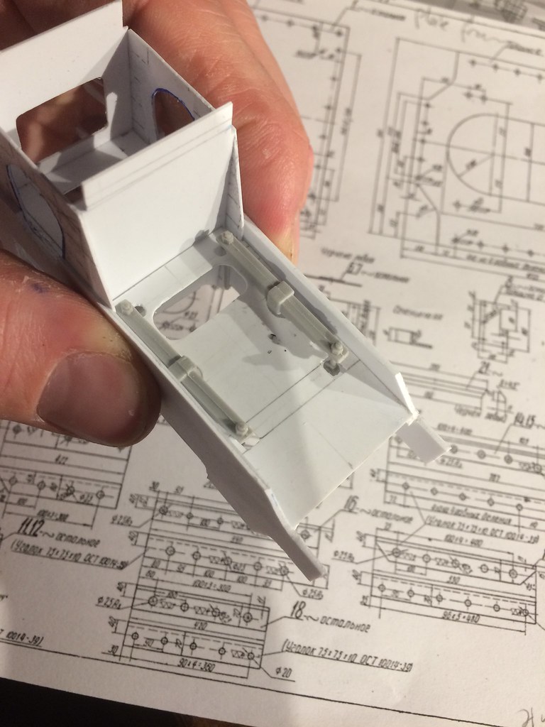
The front is coming together step by step. Managed to cut the frontal upper support structure. A comparison to the kit part shows some major differences and additions. The should look nice in the end and actually be noticeable.
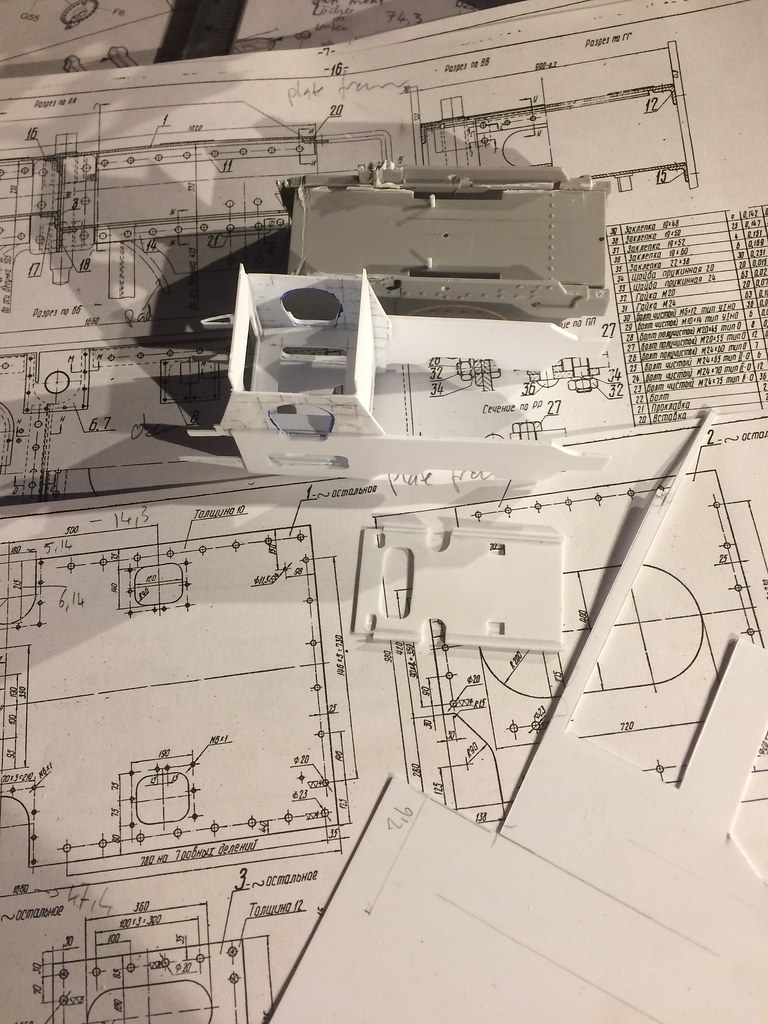
And the spring parts fit just perfectly, however they will be adjusted nonetheless.
Have a good one, C&Cs welcome, cheers
/Stefan
will message them and ask.
The front is coming together step by step. Managed to cut the frontal upper support structure. A comparison to the kit part shows some major differences and additions. The should look nice in the end and actually be noticeable.

And the spring parts fit just perfectly, however they will be adjusted nonetheless.

Have a good one, C&Cs welcome, cheers
/Stefan
Posted: Monday, March 13, 2017 - 05:42 AM UTC
Very fine work Stefan ! The latest parts look perfect against the drawings. please do carry on 

27-1025

Joined: September 16, 2004
KitMaker: 1,281 posts
Armorama: 1,222 posts

Posted: Monday, March 13, 2017 - 06:58 AM UTC
Amazing work. Looking forward to seeing your progress.

Blaubar

Joined: December 15, 2016
KitMaker: 261 posts
Armorama: 246 posts

Posted: Tuesday, March 14, 2017 - 11:54 AM UTC
Thanks you two, as this is my second scratch project, along with the Waffentraeger ardelt, I guess I am learning lots along the way. Never thought of these changes when I started the project and as sich I hope it will be all right in the end, despite the flaws and lack of experience.
Prost,
/Stefan
Prost,
/Stefan

Blaubar

Joined: December 15, 2016
KitMaker: 261 posts
Armorama: 246 posts

Posted: Sunday, March 26, 2017 - 08:32 PM UTC
Good evening together,
I have done just a bit of the frame interior of the lower front.
Some sparrings for the leaf spring system and access holes for various parts had to be cut. The lower level horizontal support is at two different levels, the front part (longer one with the long hole) is slightly lower than the aft part (behind the vertical separator)
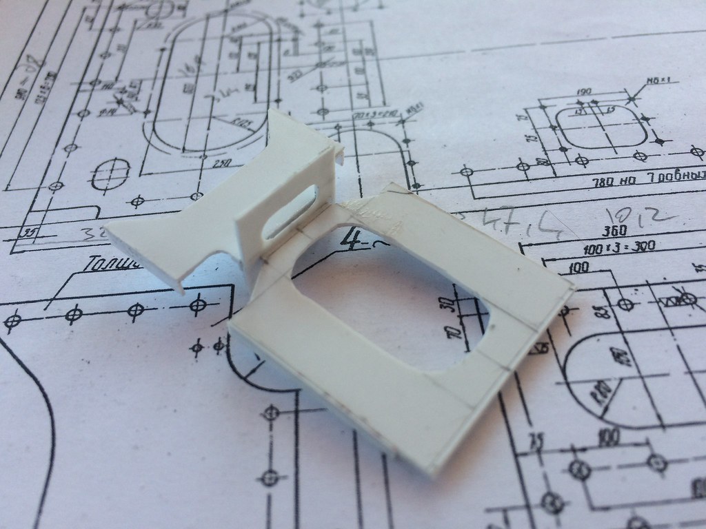
Here the lower basic frame parts in front of the frame.
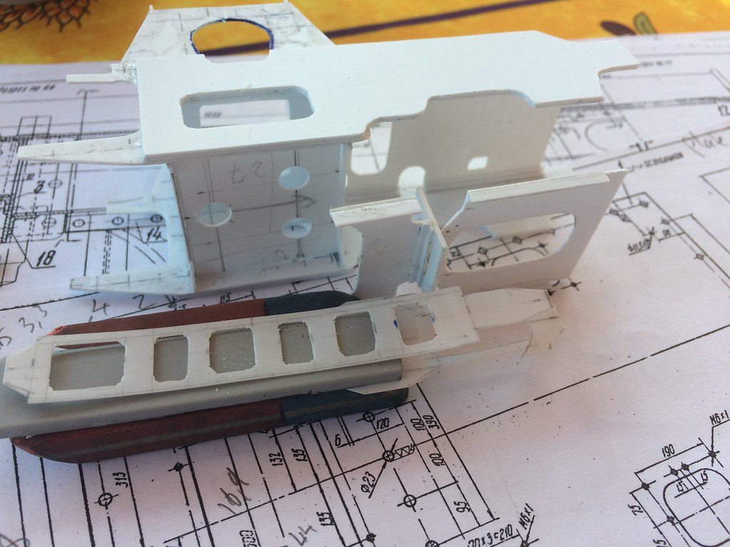
The view from the front:
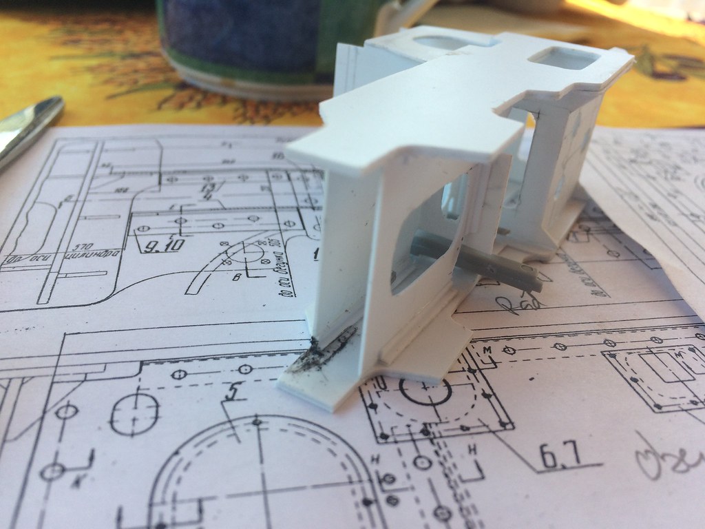
Vie from below:
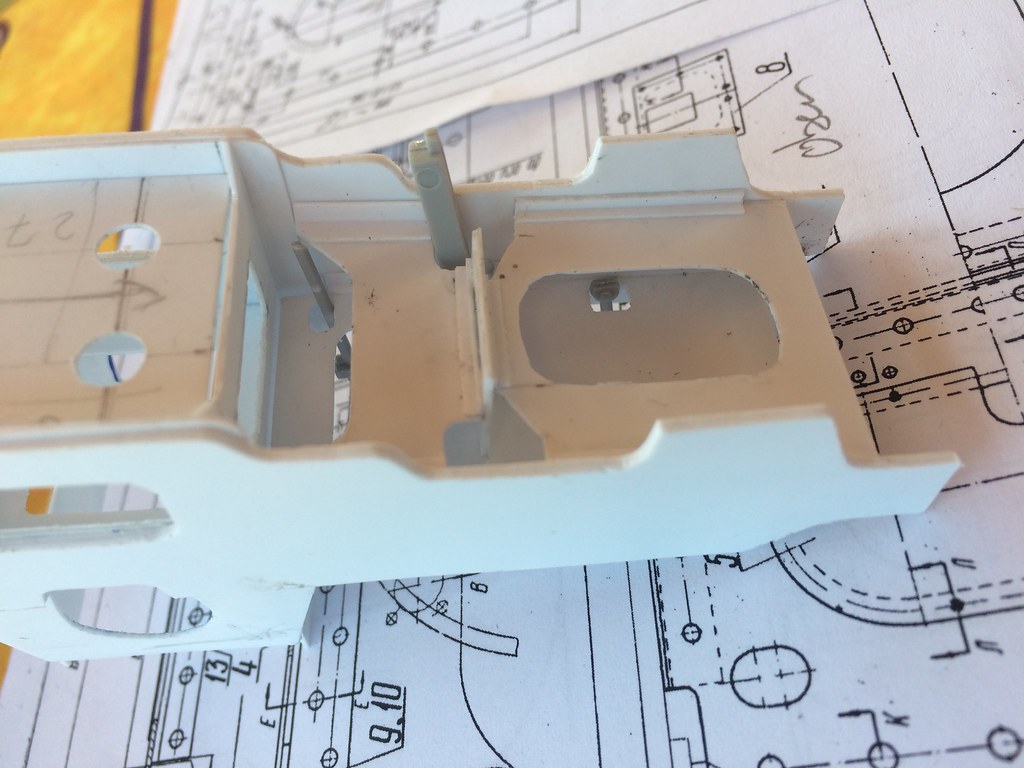
It is not part of the kit, the lower frame supports are not represented, only the crude to of the frame is included in the Trumpy sprues.
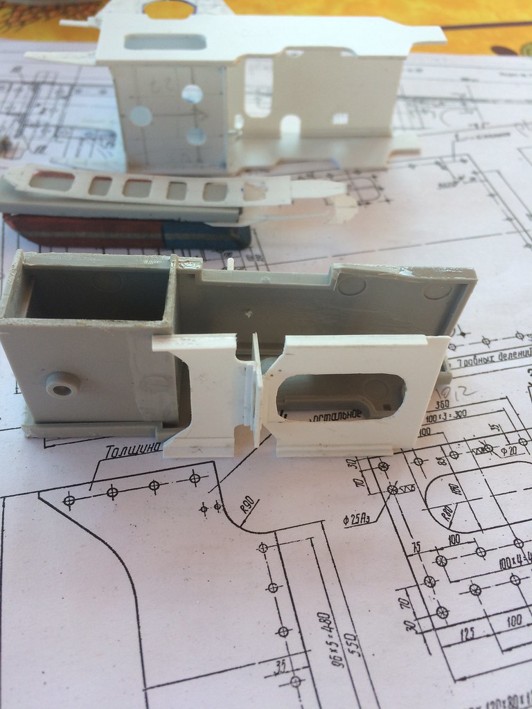
Haae e good week all,
/STefan
I have done just a bit of the frame interior of the lower front.
Some sparrings for the leaf spring system and access holes for various parts had to be cut. The lower level horizontal support is at two different levels, the front part (longer one with the long hole) is slightly lower than the aft part (behind the vertical separator)

Here the lower basic frame parts in front of the frame.

The view from the front:

Vie from below:

It is not part of the kit, the lower frame supports are not represented, only the crude to of the frame is included in the Trumpy sprues.

Haae e good week all,
/STefan
celt15

Joined: September 16, 2016
KitMaker: 95 posts
Armorama: 91 posts

Posted: Sunday, March 26, 2017 - 10:36 PM UTC
Just read this thread,its truly amazing work,words fail me.Outstanding.

Blaubar

Joined: December 15, 2016
KitMaker: 261 posts
Armorama: 246 posts

Posted: Thursday, March 30, 2017 - 03:34 AM UTC
Cheers to you Mr Cymru,
Trying hard to get something reasonable out of this.
/Stefan
Trying hard to get something reasonable out of this.
/Stefan
jrutman

Joined: April 10, 2011
KitMaker: 7,941 posts
Armorama: 7,934 posts

Posted: Thursday, March 30, 2017 - 06:23 PM UTC
I am still following along and still think this is one of the best builds ever on this website. Scratchbuilding is model building in its' purest form. You are really doing a fantastic job bringing the cold hard 2-D drawings to life.
J
J

Blaubar

Joined: December 15, 2016
KitMaker: 261 posts
Armorama: 246 posts

Posted: Friday, March 31, 2017 - 12:53 AM UTC
Jarry, thanks.
The Ratte blog is my favourite, the guy building the 1:35 Ratte is totally amazing.
I had a few things which I forgot to add. Additionally some new lower frame plating has been cut for the rear of the boiler support. Many more lower frame parts are yet to be added, but I think I need to clean, sand, prepare and paint the interior first.
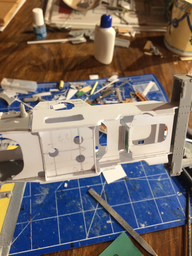
There are so many holes and sparrings, no clue how to paint all this... Maybe I need to start priming and preparing it now before assembly, especially now that the drive shaft springs have been added below:
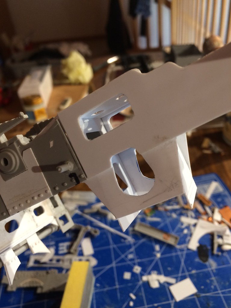
It needs some trimming and sanding and the top got broken so needs to be done anew but it does help with the impression, even though it is not even aligned properly^^. Actually what is on top now, will later be the bottom side of it, the front is to the right. It does differ substantially from the kit now.
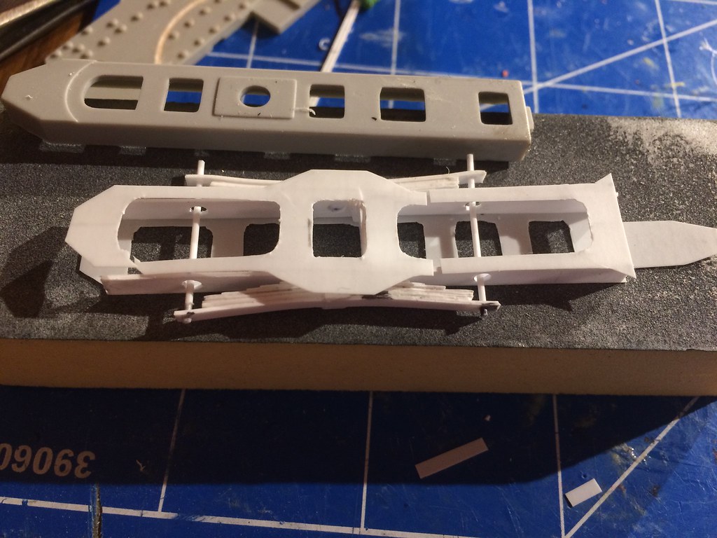
Seen from the top it will be about in this place below the whole frame.
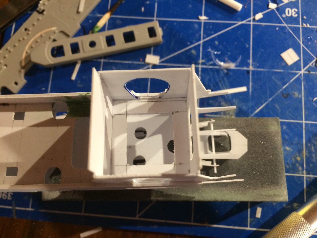
The single hole in the rear of the boiler support will be bolted to the centre of the leaf springs and it will be able to "swing freely" (it was anyways in the real engine). The spring connection rods are not perfectly aligned, they are bent a bit, so I will drill a different hole and align them again and thereafter I will cut the slag off the edges of the rods as they are yet too long.
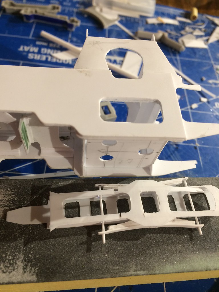
Still so much more to do, but at least some progress. Have a good evening. I enjoy building this thing, the plans and original designs I found are quite nice and I am getting along better with all the styrene by now. As this and the Waffentrager are my first scratch attempts, I feel I am getting used to this and I hope it will pay off in the end.
Cheers all,
Prost,
/Stefan
The Ratte blog is my favourite, the guy building the 1:35 Ratte is totally amazing.
I had a few things which I forgot to add. Additionally some new lower frame plating has been cut for the rear of the boiler support. Many more lower frame parts are yet to be added, but I think I need to clean, sand, prepare and paint the interior first.

There are so many holes and sparrings, no clue how to paint all this... Maybe I need to start priming and preparing it now before assembly, especially now that the drive shaft springs have been added below:

It needs some trimming and sanding and the top got broken so needs to be done anew but it does help with the impression, even though it is not even aligned properly^^. Actually what is on top now, will later be the bottom side of it, the front is to the right. It does differ substantially from the kit now.

Seen from the top it will be about in this place below the whole frame.

The single hole in the rear of the boiler support will be bolted to the centre of the leaf springs and it will be able to "swing freely" (it was anyways in the real engine). The spring connection rods are not perfectly aligned, they are bent a bit, so I will drill a different hole and align them again and thereafter I will cut the slag off the edges of the rods as they are yet too long.

Still so much more to do, but at least some progress. Have a good evening. I enjoy building this thing, the plans and original designs I found are quite nice and I am getting along better with all the styrene by now. As this and the Waffentrager are my first scratch attempts, I feel I am getting used to this and I hope it will pay off in the end.
Cheers all,
Prost,
/Stefan

Blaubar

Joined: December 15, 2016
KitMaker: 261 posts
Armorama: 246 posts

Posted: Monday, April 03, 2017 - 11:39 PM UTC
A lot of sanding is needed and more detailing, but I think I will paint it tonight before continuing. This was before major changes were added and parts reshaped:
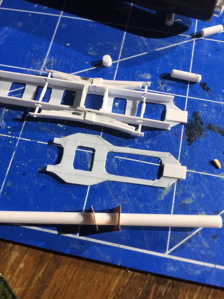
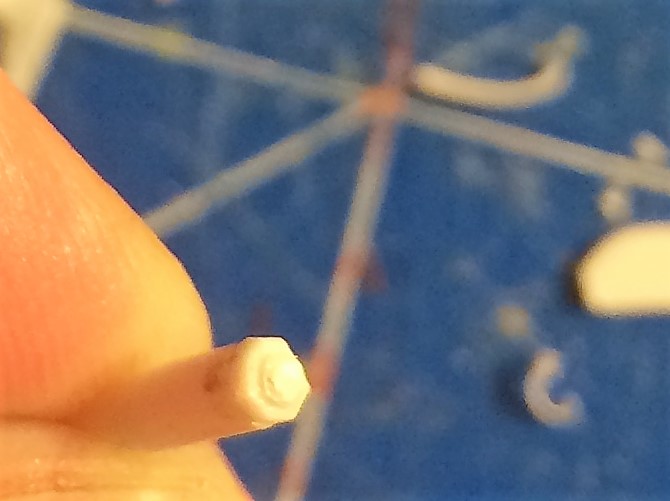
This is the bolt that will connect the leading axle to the first powered axle. It is a 2mm rod, on top of which is a .8mm thick disc (2.5mm diameter) which I cut into a hexagon and on top of it is a tiny disc of 1.5mm in diameter. The side I am holding will be within a boxed casing attached to the first powered axle (from the front).
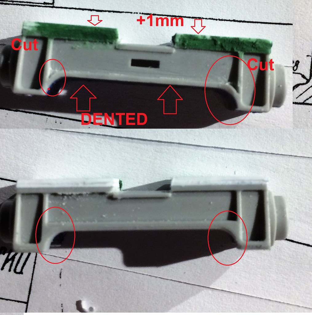
The next step was an annoying part as much plastic had to be cut away at the bottom (second picture) then some plastic card had to be added to the top and then the sides had to be reshaped to come up for the curvature (the centre of the cross section was thinner than the outside - see my nasty drawings on the second picture). Also a few cuts were needed to cut away the recess where the rims of the vertical support join the horizontal support beams. (the four circles show this: on the bottom is the stock kit, on top is the modified version.)
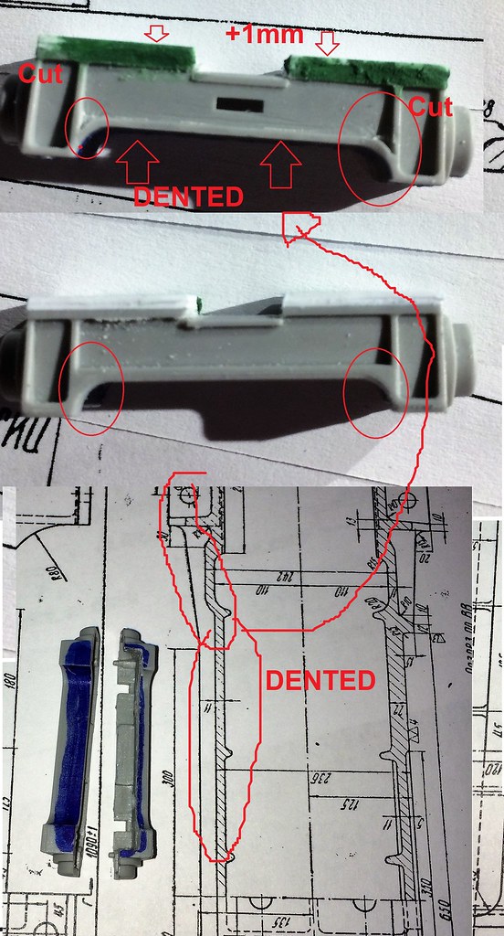
Maybe this drawing helps to show what I am trying to explain... This also shows what had to be cut away at the bottom (blue markings). The kit part has the bottom enclosed, however, it is open with the real engine:
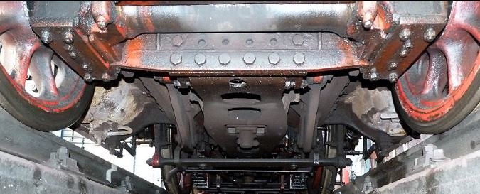
Compare the steering rack and additions:
.jpg)
1)
2)
Notice however that both shown driving racks are of different shapes and both are no original ones and do differ slightly! But they do help depict the general shape and problems.
The advanced and further modified steering rack laying on the boiler support.
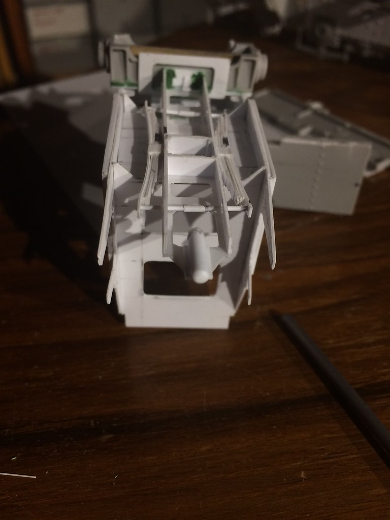
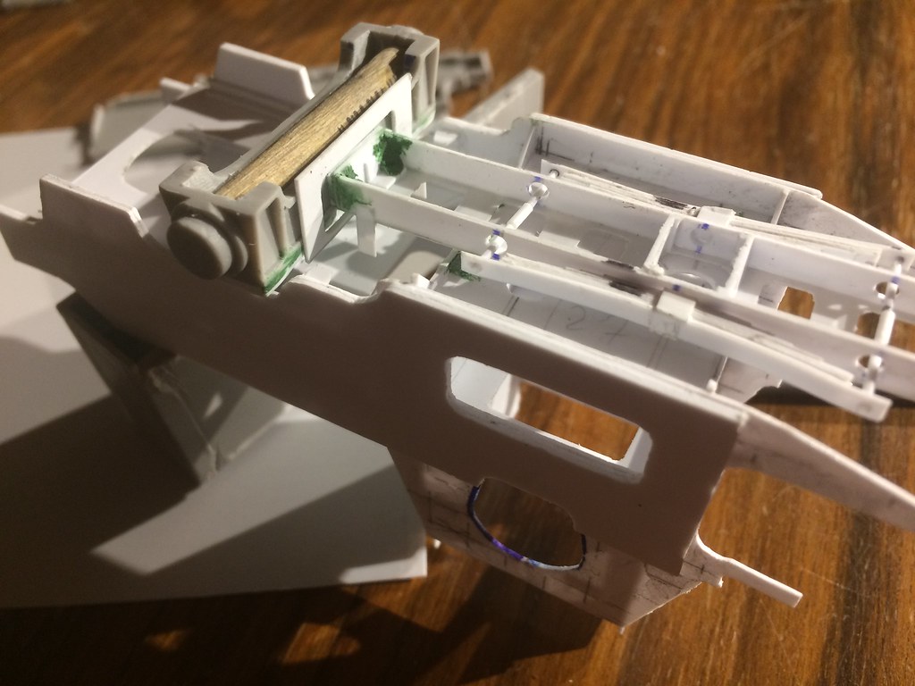
In the meantime, I added the screw mechanism for the leaf spring pre-tension torsion bars.
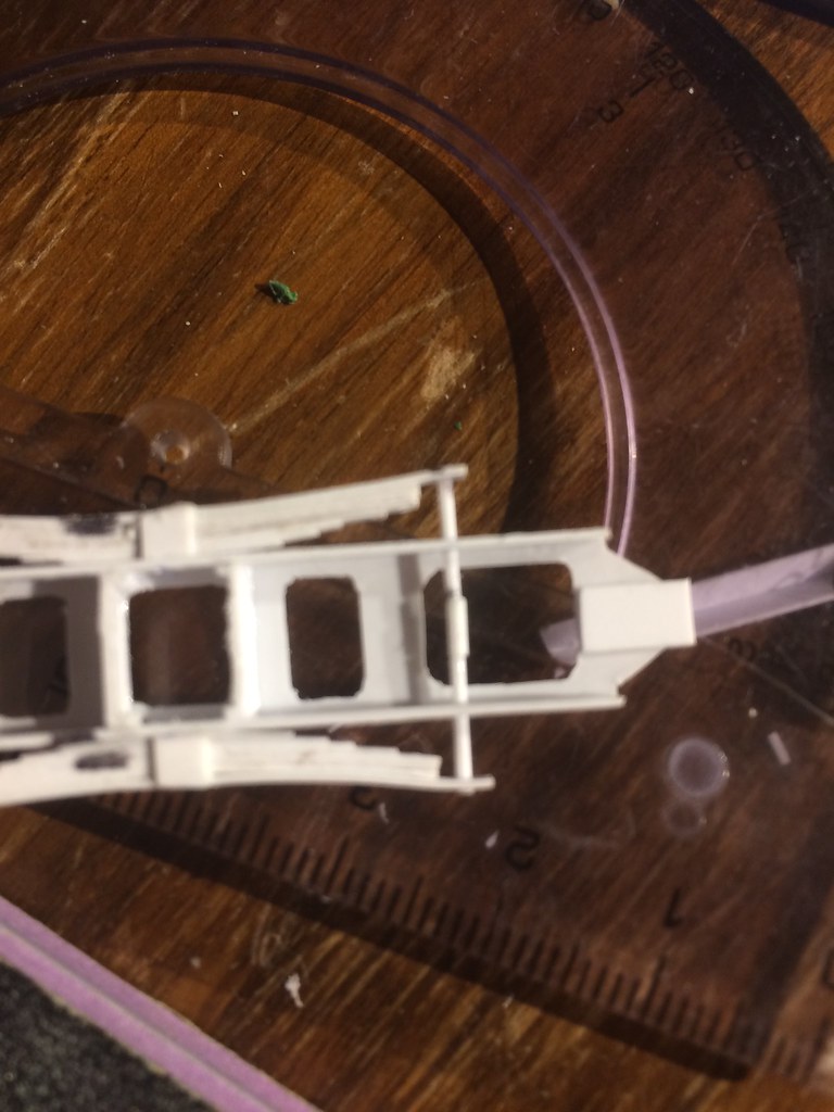
The top has been modified towards the front with the guiding support T-section in the front.
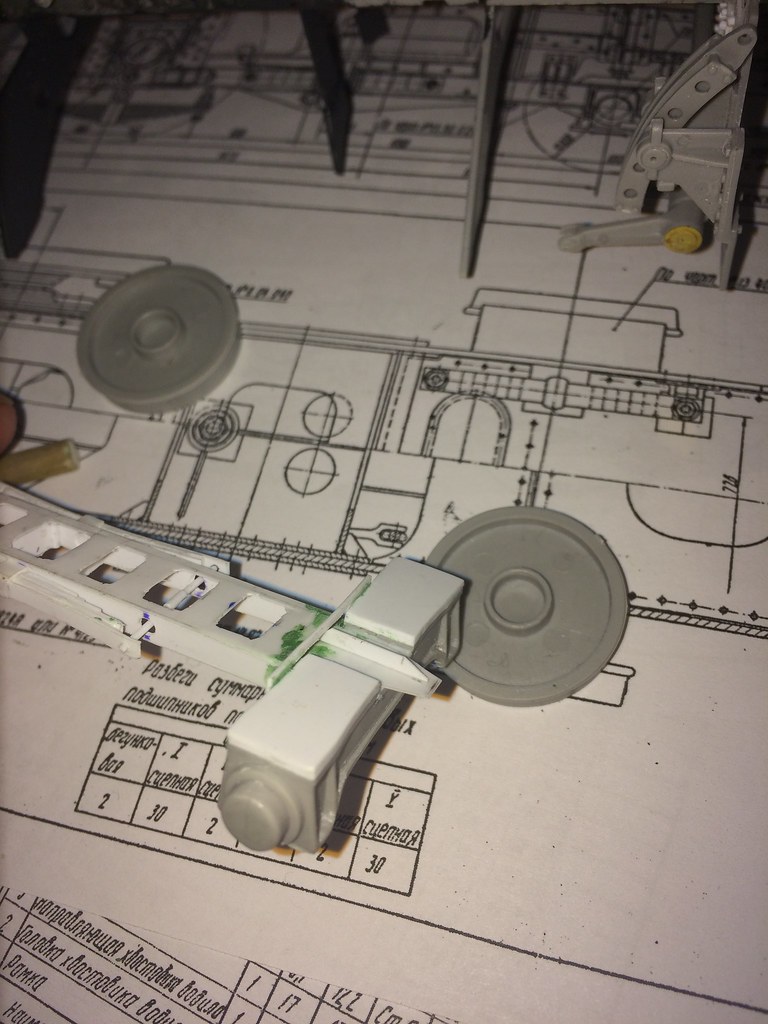
Finally with wheels in place to have an alignment check. The top of the steering rack needs to be just below the second swing within the frame and slightly above the very bottom of the frame. If this is misaligned, the leading wheels will hang loose in the air and as such this is a difficult part as all parts need to be assembled and painted and then put together, and only then will I know if it worked (as all will be moving parts and I will not glue them)
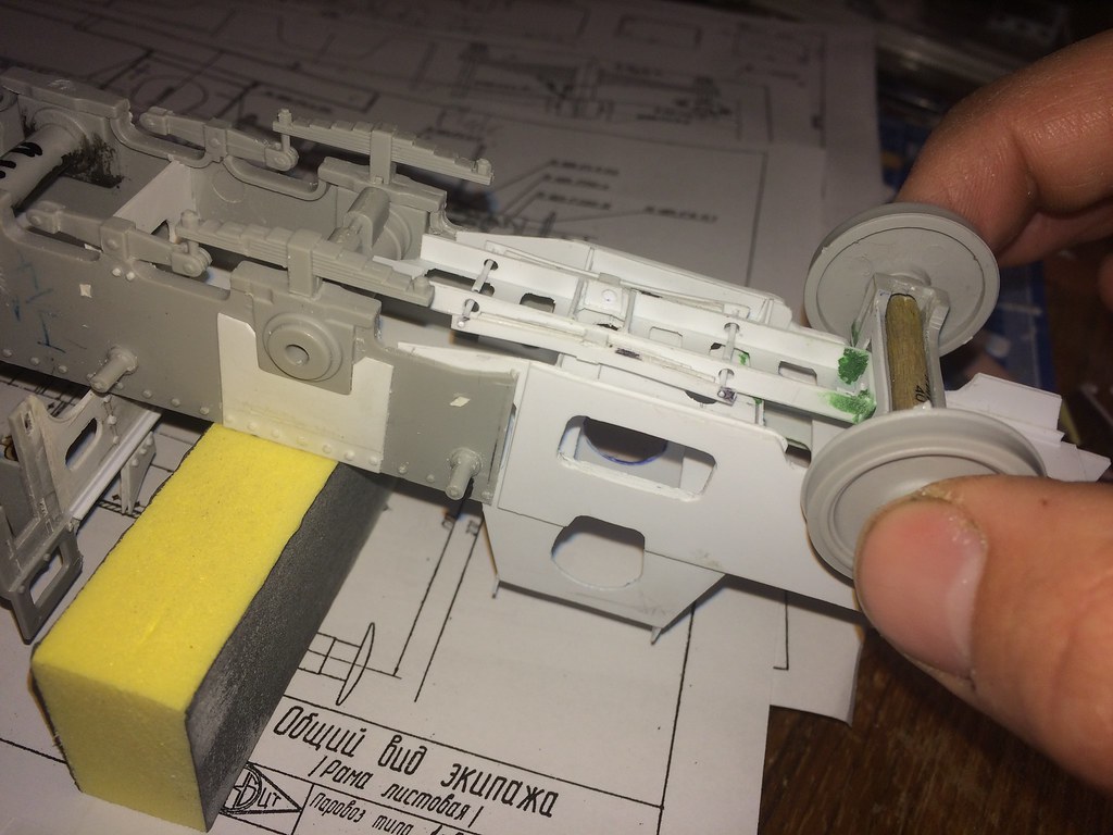
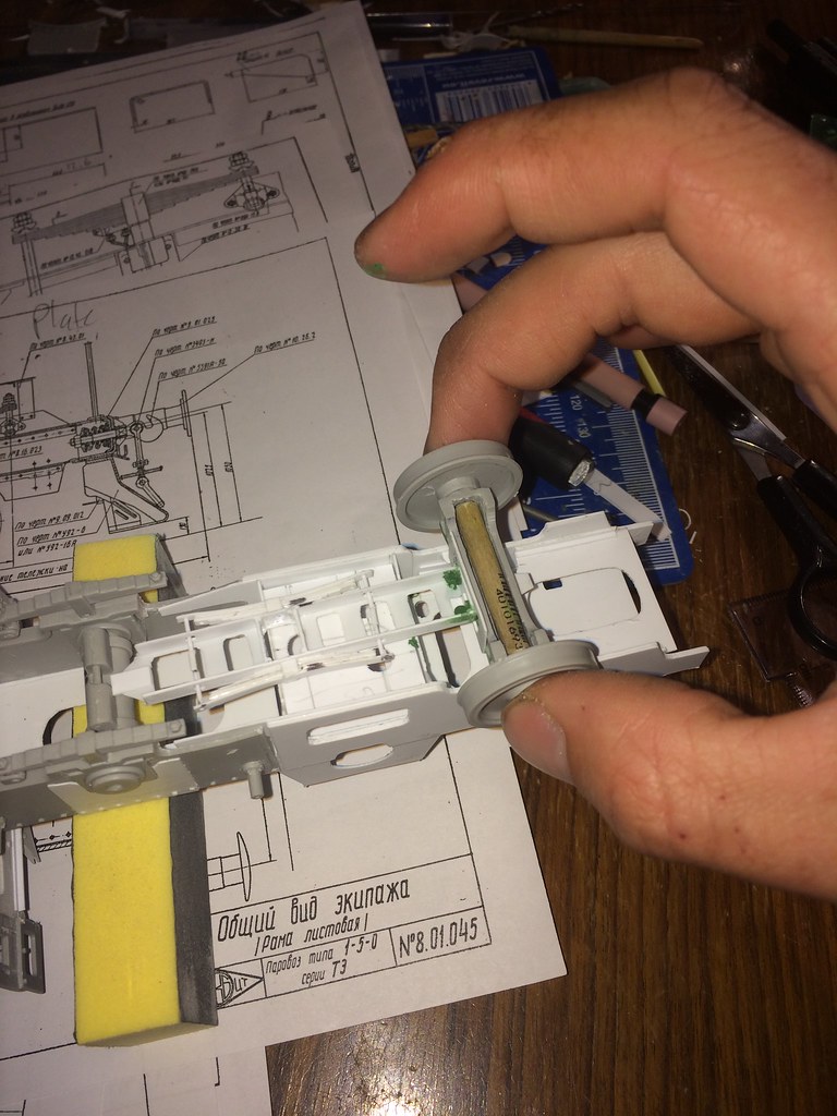
If I screw it up, I will glue it down in the worst case^^
Have a great evening, hope you like it and I am not boring anyone.
/Stefan
sources:
1) http://www.eisenbahnfreunde-zollernbahn.de/
2) https://www.dampflok526106.de/galerie/52-6106-im-jahr-2012/

This is the bolt that will connect the leading axle to the first powered axle. It is a 2mm rod, on top of which is a .8mm thick disc (2.5mm diameter) which I cut into a hexagon and on top of it is a tiny disc of 1.5mm in diameter. The side I am holding will be within a boxed casing attached to the first powered axle (from the front).

The next step was an annoying part as much plastic had to be cut away at the bottom (second picture) then some plastic card had to be added to the top and then the sides had to be reshaped to come up for the curvature (the centre of the cross section was thinner than the outside - see my nasty drawings on the second picture). Also a few cuts were needed to cut away the recess where the rims of the vertical support join the horizontal support beams. (the four circles show this: on the bottom is the stock kit, on top is the modified version.)

Maybe this drawing helps to show what I am trying to explain... This also shows what had to be cut away at the bottom (blue markings). The kit part has the bottom enclosed, however, it is open with the real engine:

Compare the steering rack and additions:
.jpg)
1)

2)
Notice however that both shown driving racks are of different shapes and both are no original ones and do differ slightly! But they do help depict the general shape and problems.
The advanced and further modified steering rack laying on the boiler support.


In the meantime, I added the screw mechanism for the leaf spring pre-tension torsion bars.

The top has been modified towards the front with the guiding support T-section in the front.

Finally with wheels in place to have an alignment check. The top of the steering rack needs to be just below the second swing within the frame and slightly above the very bottom of the frame. If this is misaligned, the leading wheels will hang loose in the air and as such this is a difficult part as all parts need to be assembled and painted and then put together, and only then will I know if it worked (as all will be moving parts and I will not glue them)


If I screw it up, I will glue it down in the worst case^^
Have a great evening, hope you like it and I am not boring anyone.
/Stefan
sources:
1) http://www.eisenbahnfreunde-zollernbahn.de/
2) https://www.dampflok526106.de/galerie/52-6106-im-jahr-2012/
Posted: Tuesday, April 04, 2017 - 02:55 AM UTC
fabular! i love the leaf springs and tension mechanisms 


Blaubar

Joined: December 15, 2016
KitMaker: 261 posts
Armorama: 246 posts

Posted: Tuesday, April 04, 2017 - 03:48 PM UTC
Jonathan,
They are a pain^^. And quite a few more are needed. I need to order more styrene and profiles of all kinds, I ran out of most
They are a pain^^. And quite a few more are needed. I need to order more styrene and profiles of all kinds, I ran out of most
celt15

Joined: September 16, 2016
KitMaker: 95 posts
Armorama: 91 posts

Posted: Tuesday, April 04, 2017 - 05:27 PM UTC
Still enthralled with your work.
 |


