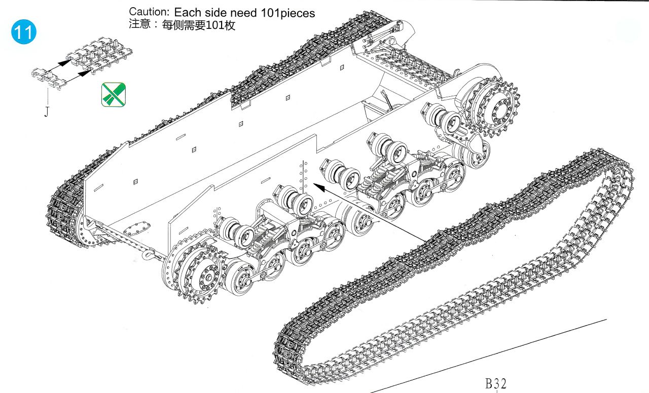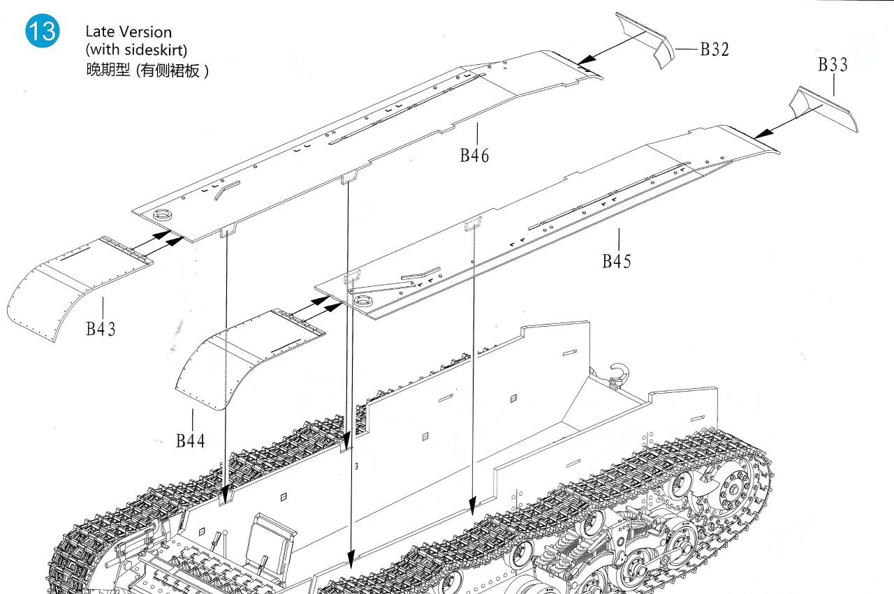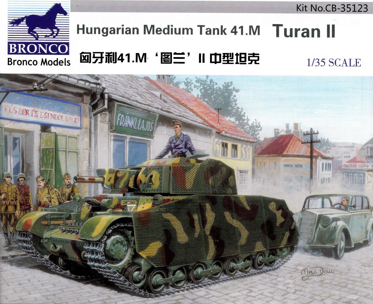
This is a review blog of Bronco's 1/35 scale Hungarian Medium Tank 41.M Turan II, kit no. CB-35123, which was supplied to Armorama as a review sample. This tank is notable for having quite complex suspension, and having built it up twice in small scale already (IBG's 1/72 Turan and Zrinyi kits) I thought I'd give Bronco's big version a go.
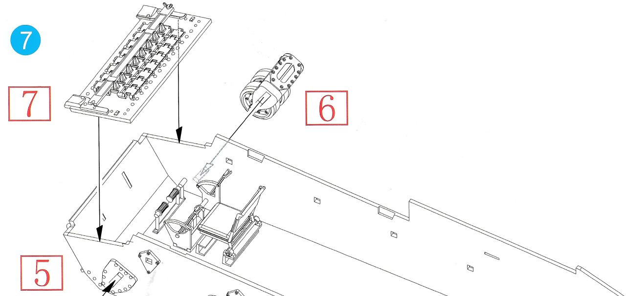
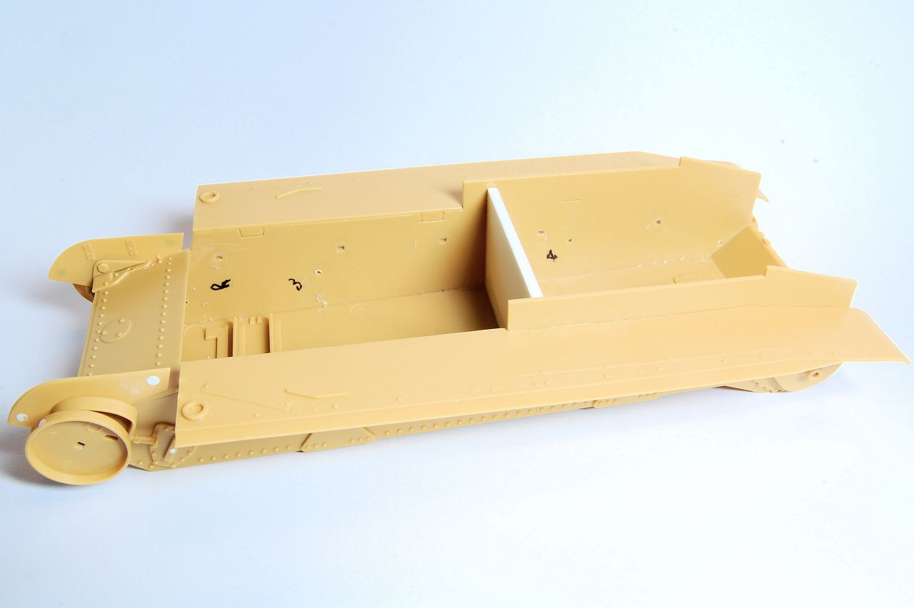
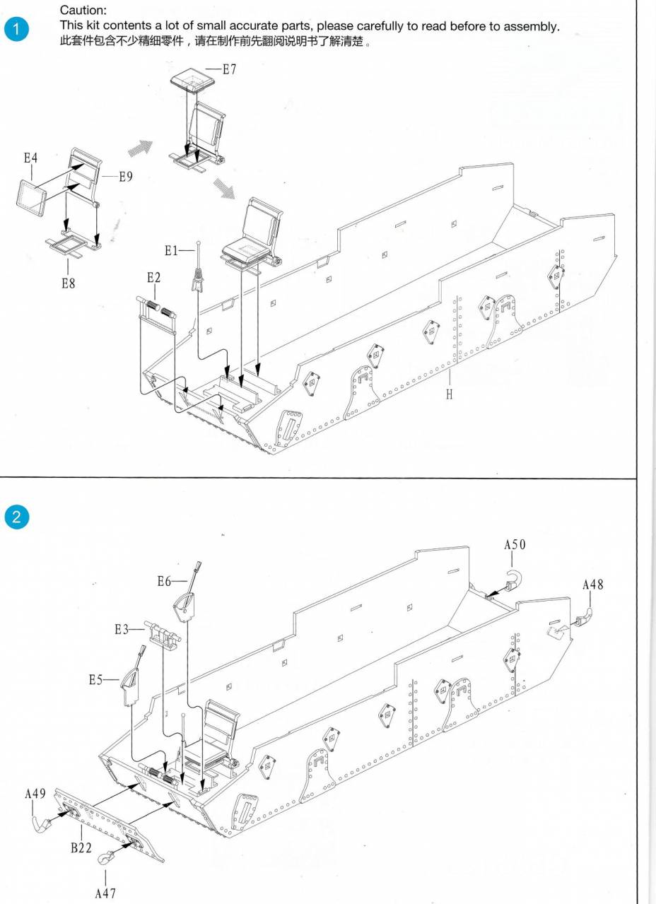
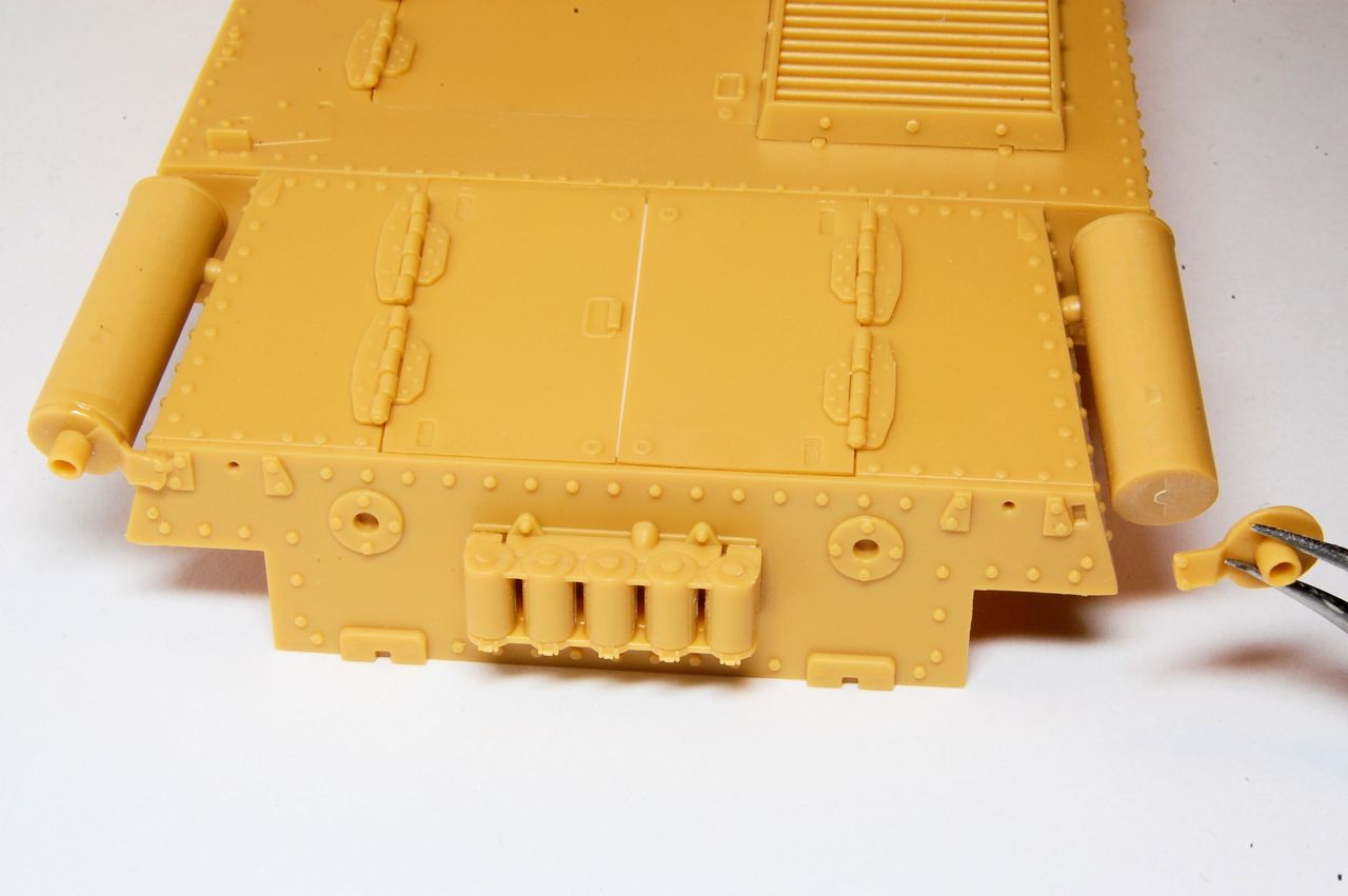
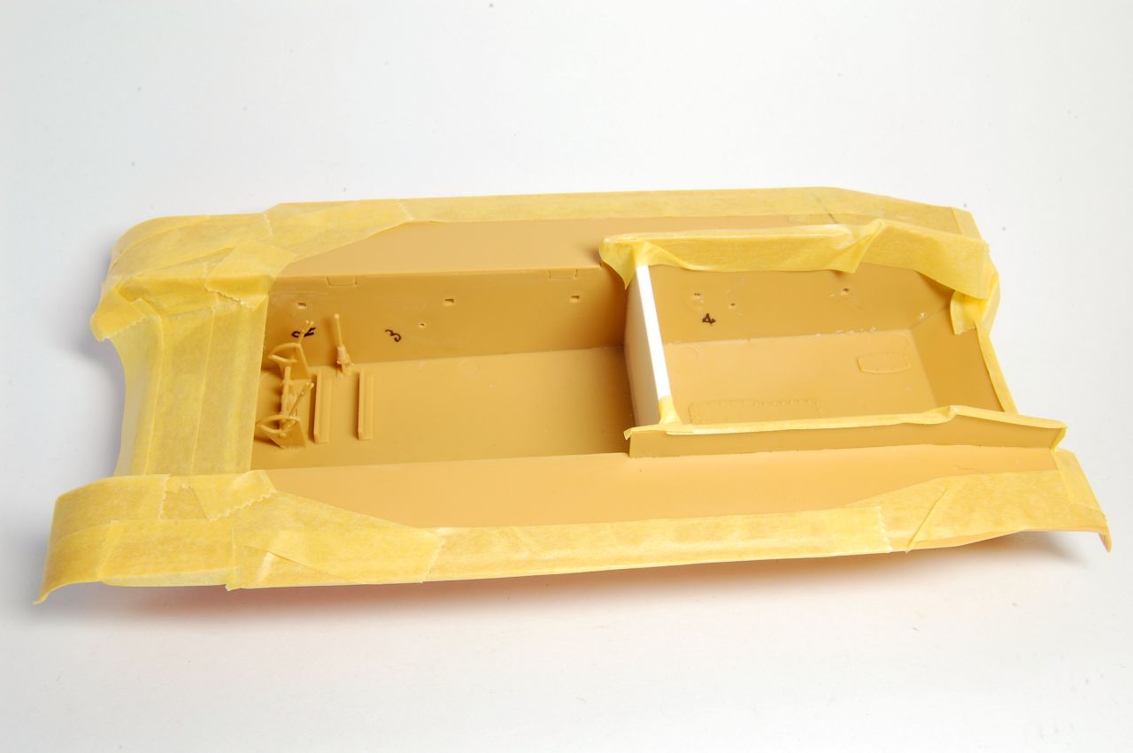
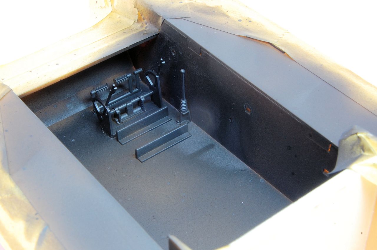
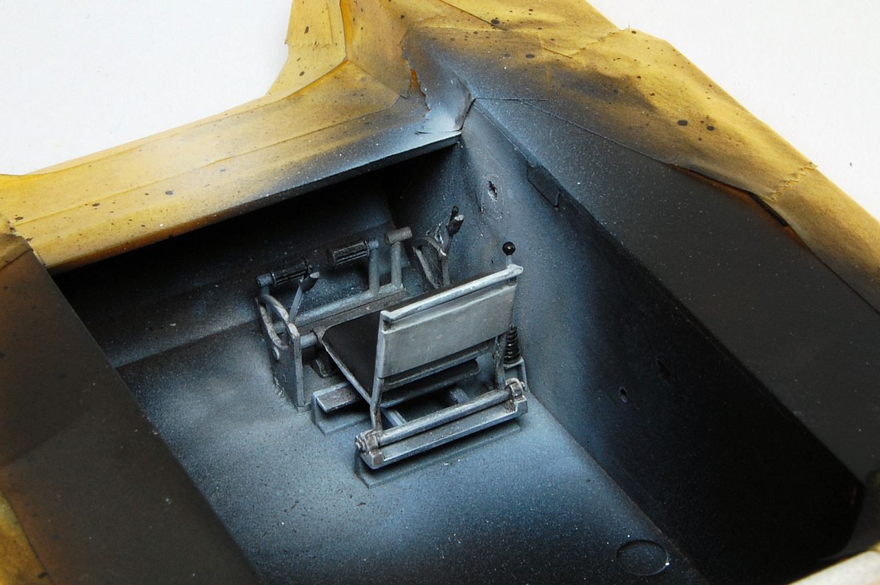
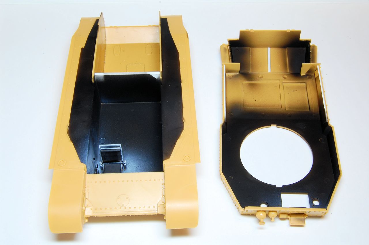
The instructions begin with two steps of installing the driver's seat and controls into the hull, and I suppose if you wanted to proceed with painting that all up before adding the wheels, and the sloping front plate that will partially cover it, then it might make sense. I was just itching to get on with the wheels though, so started at step 3:
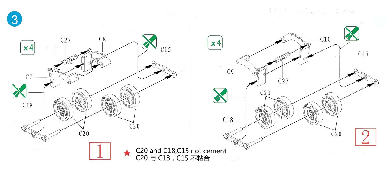
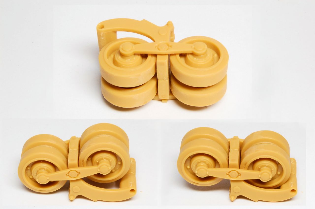
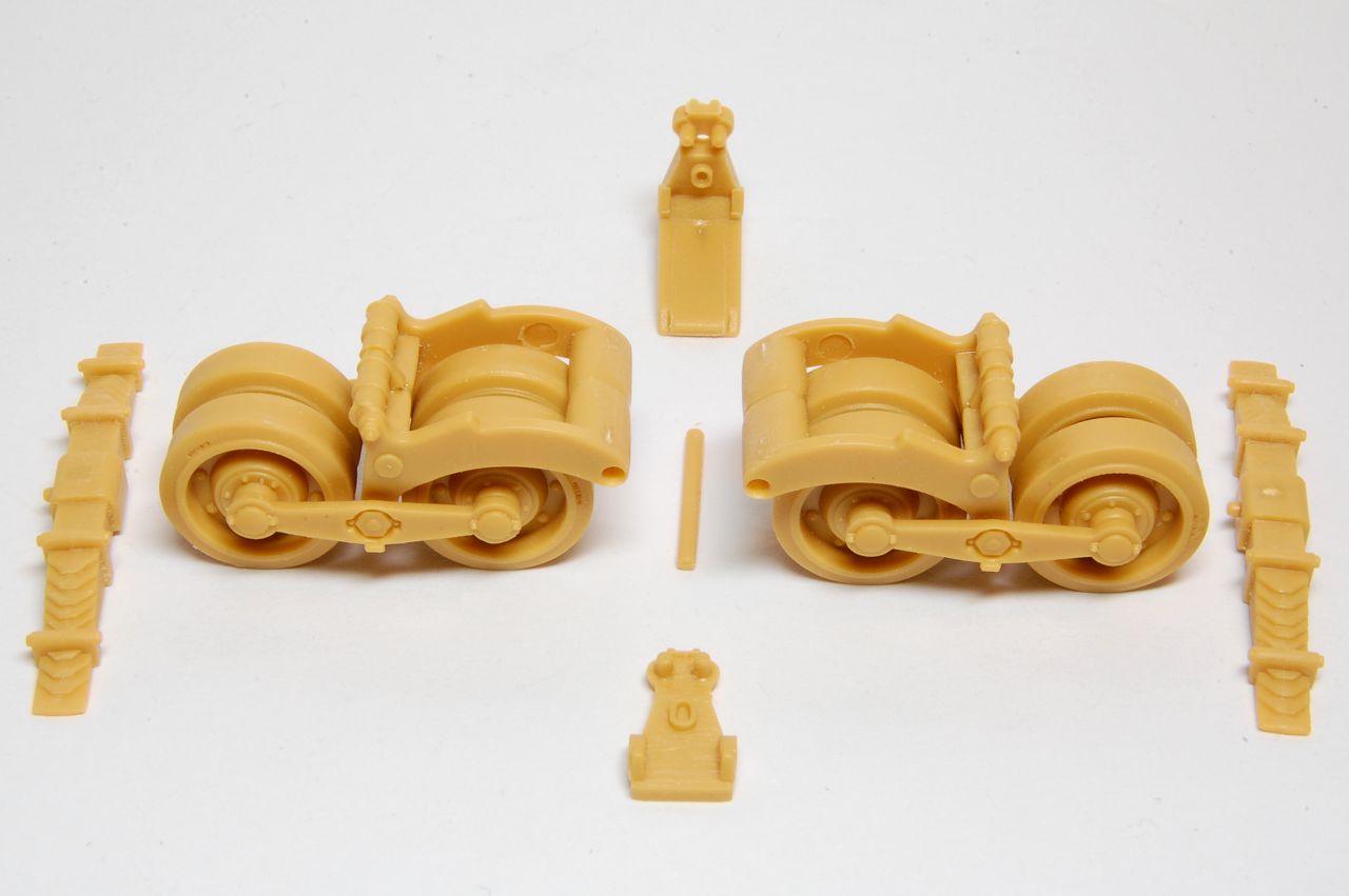
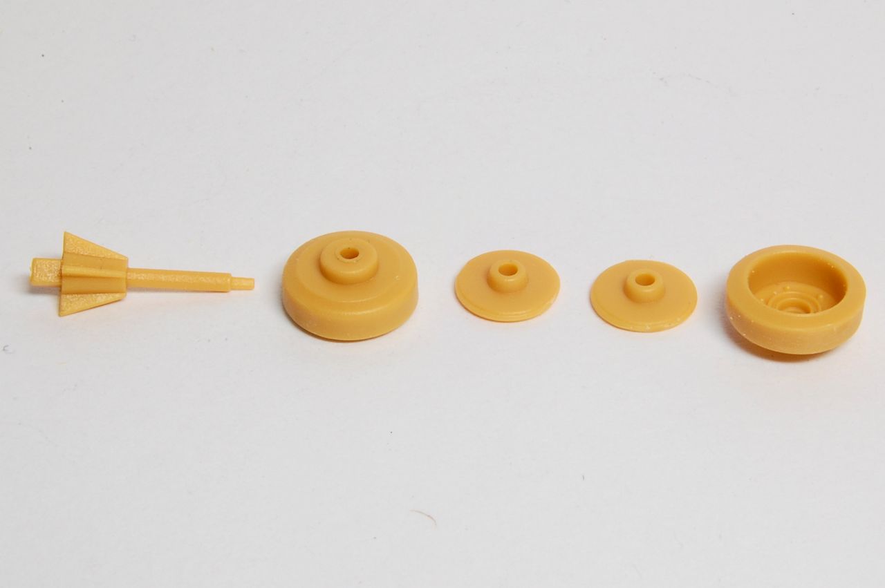
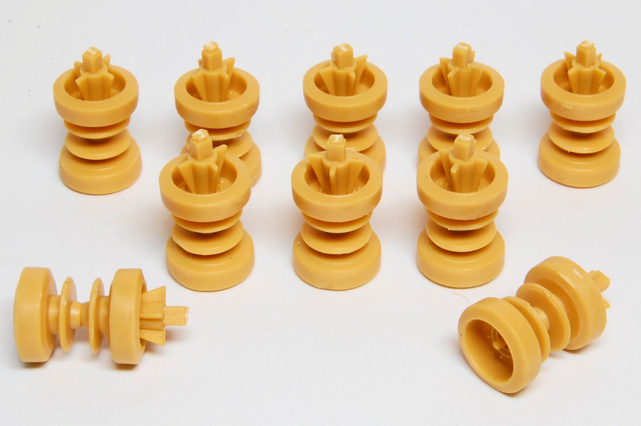
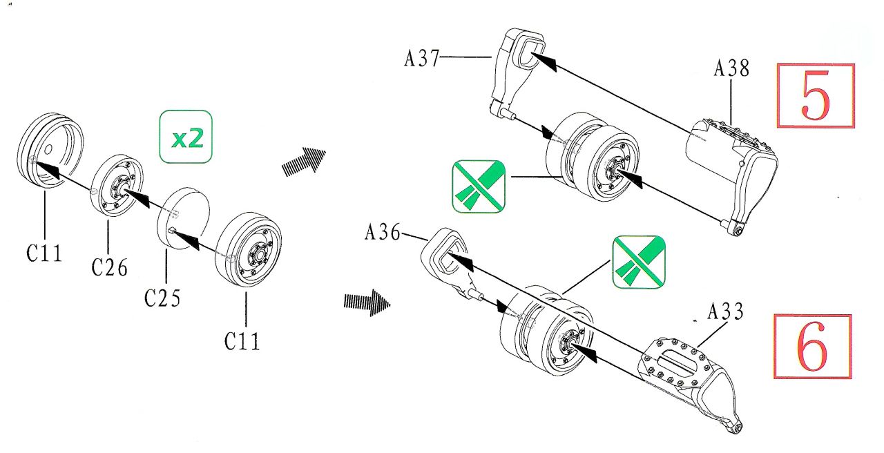
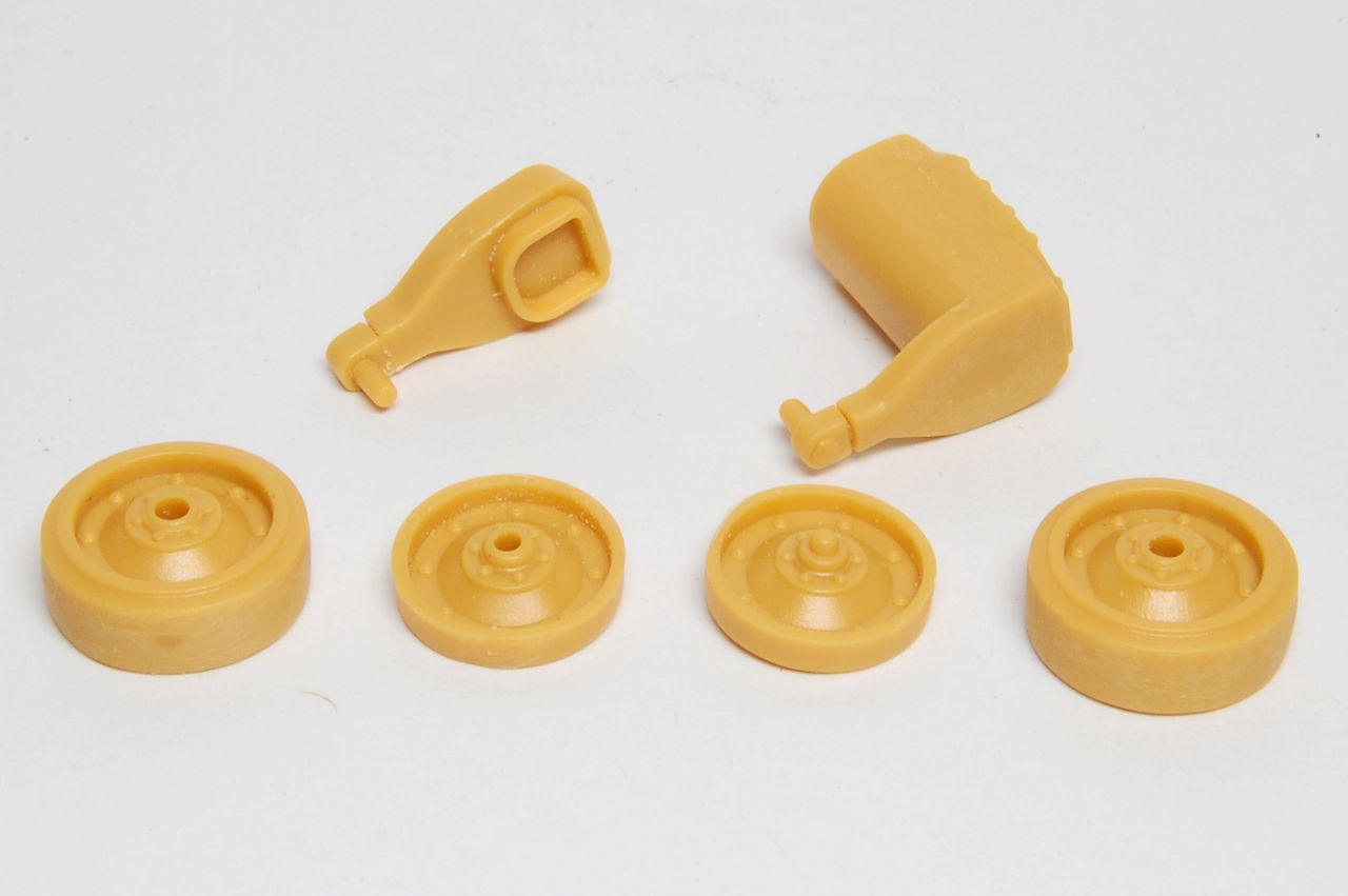
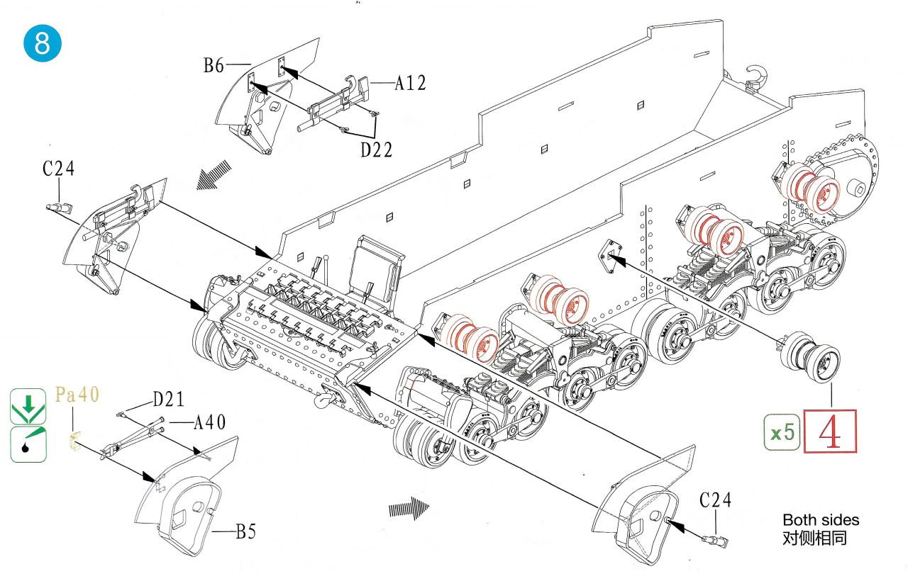
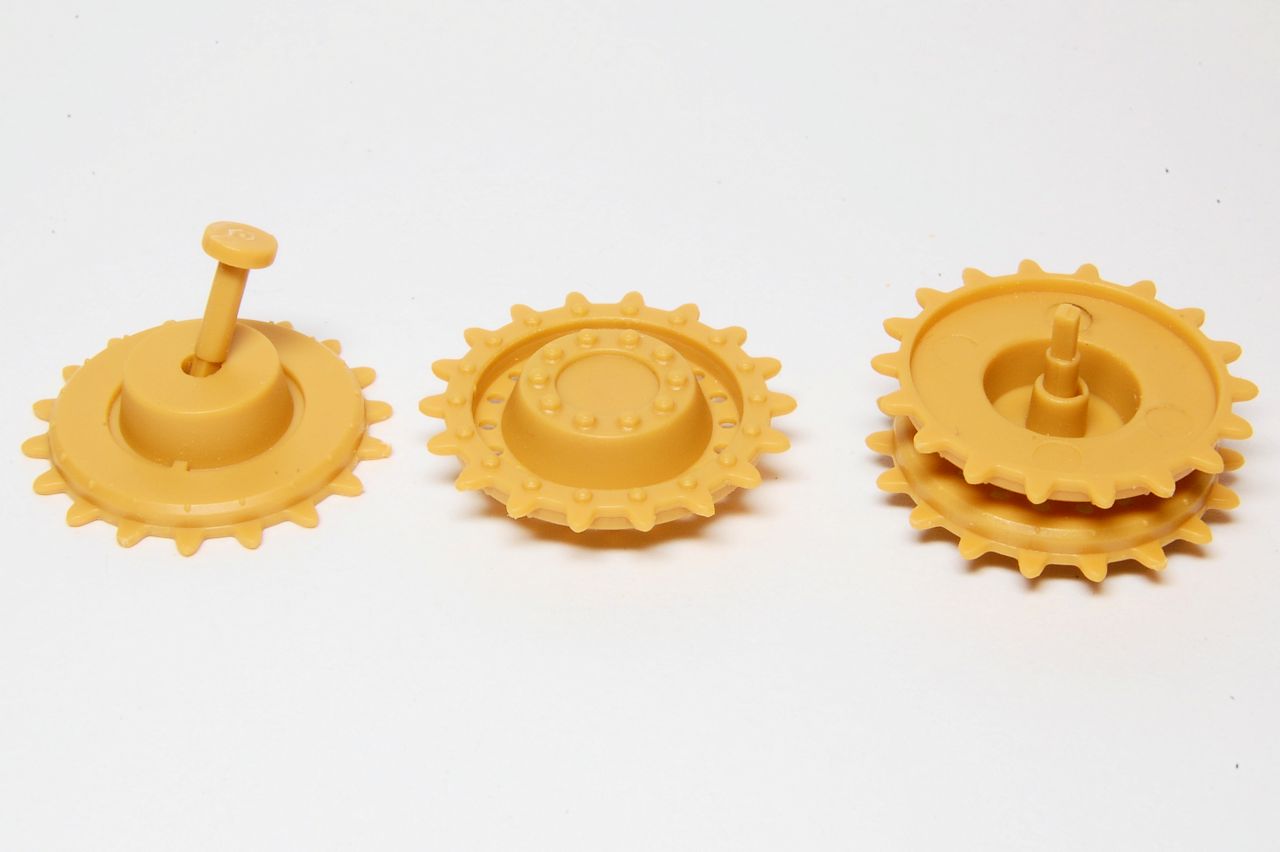
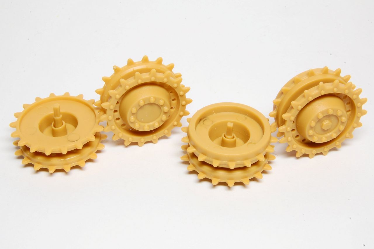
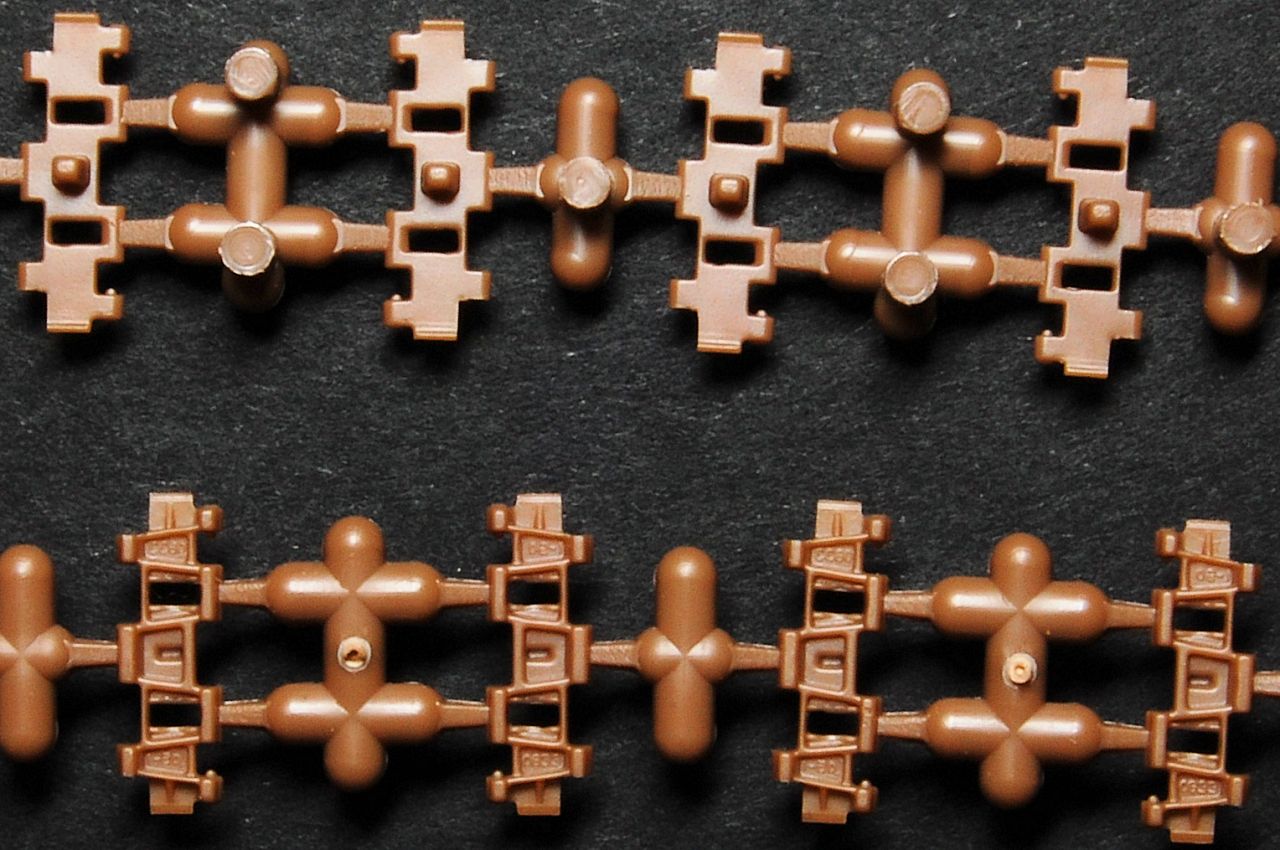
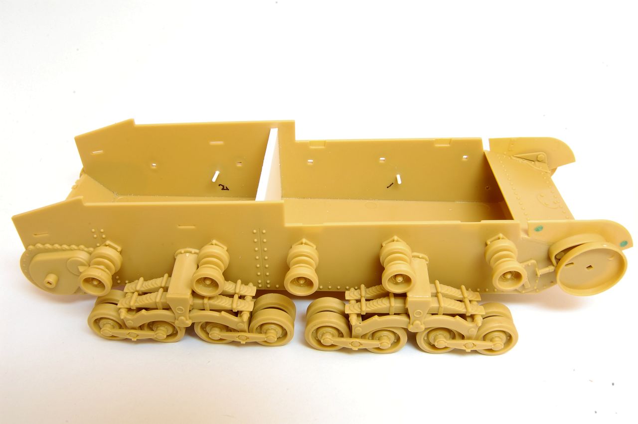
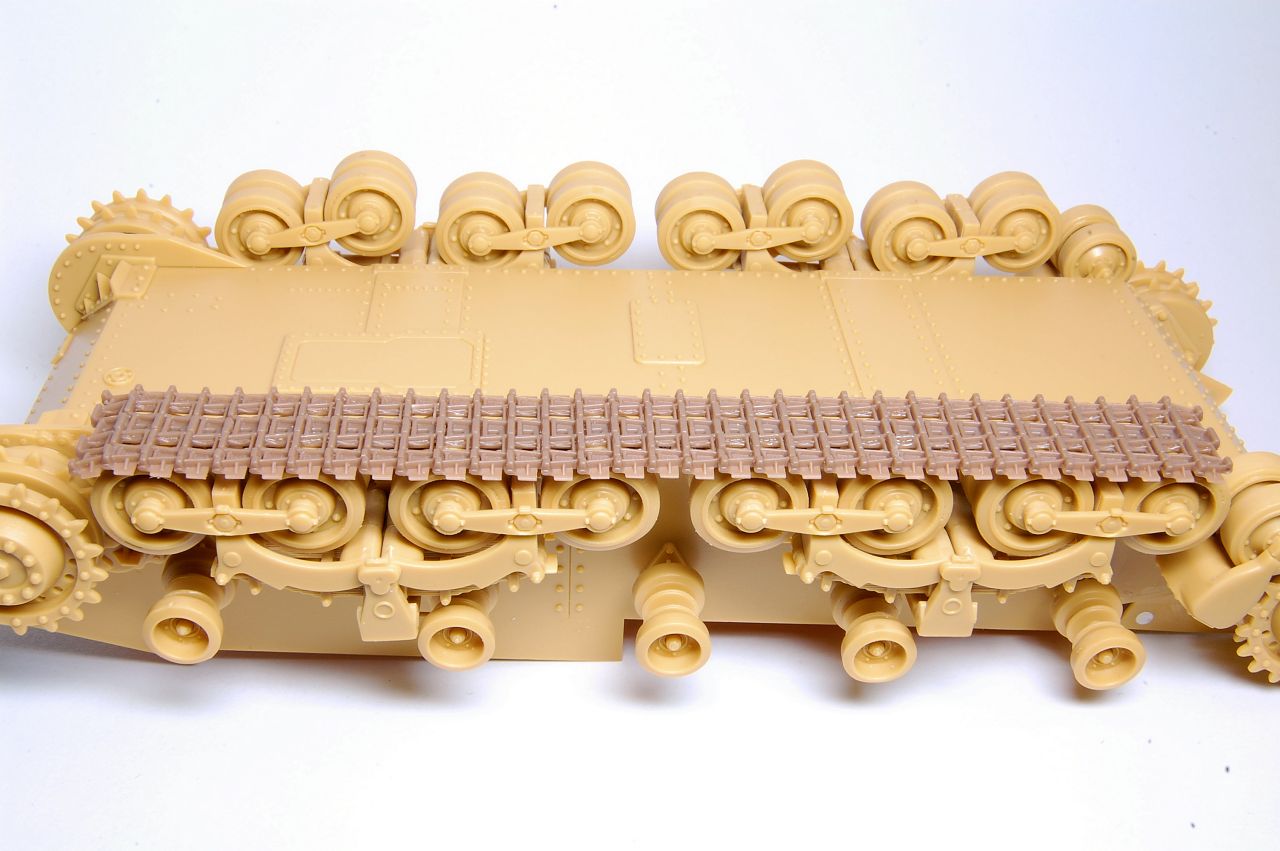
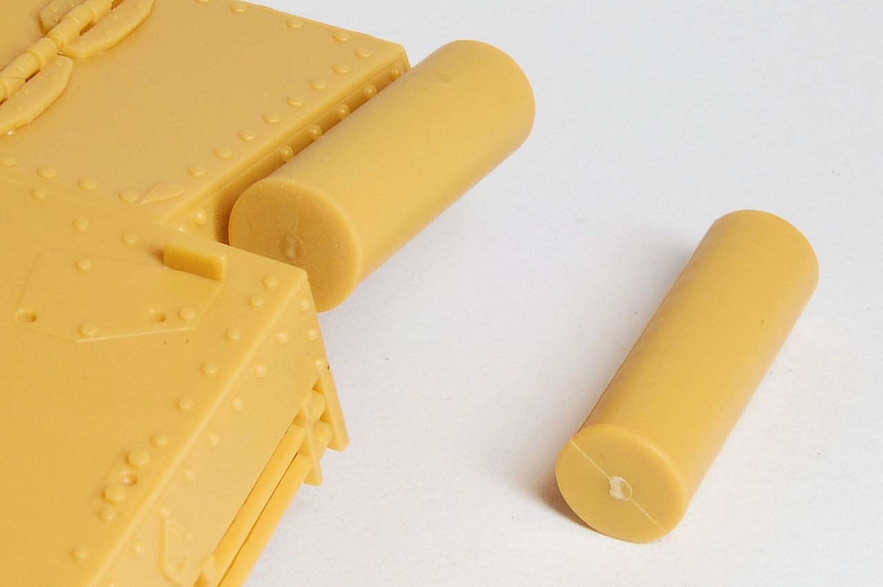
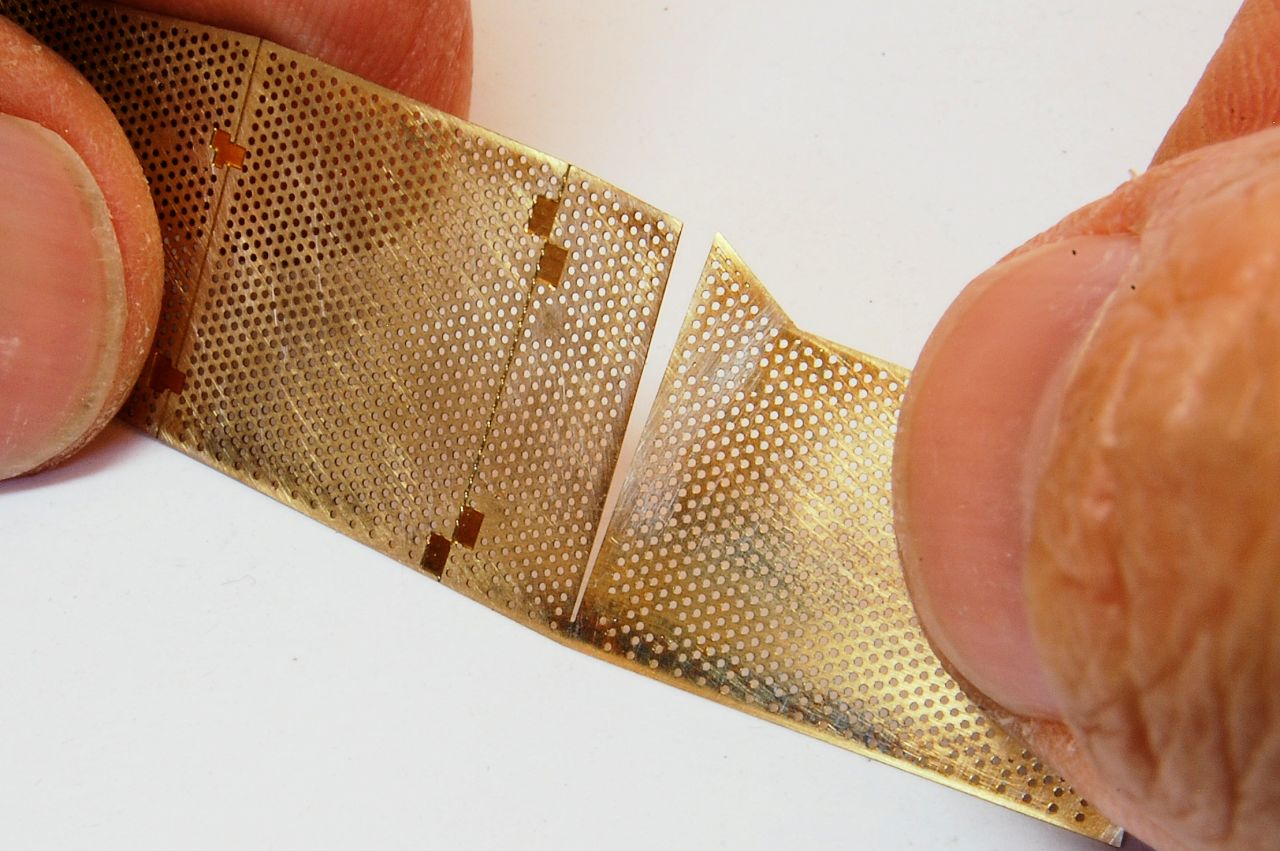
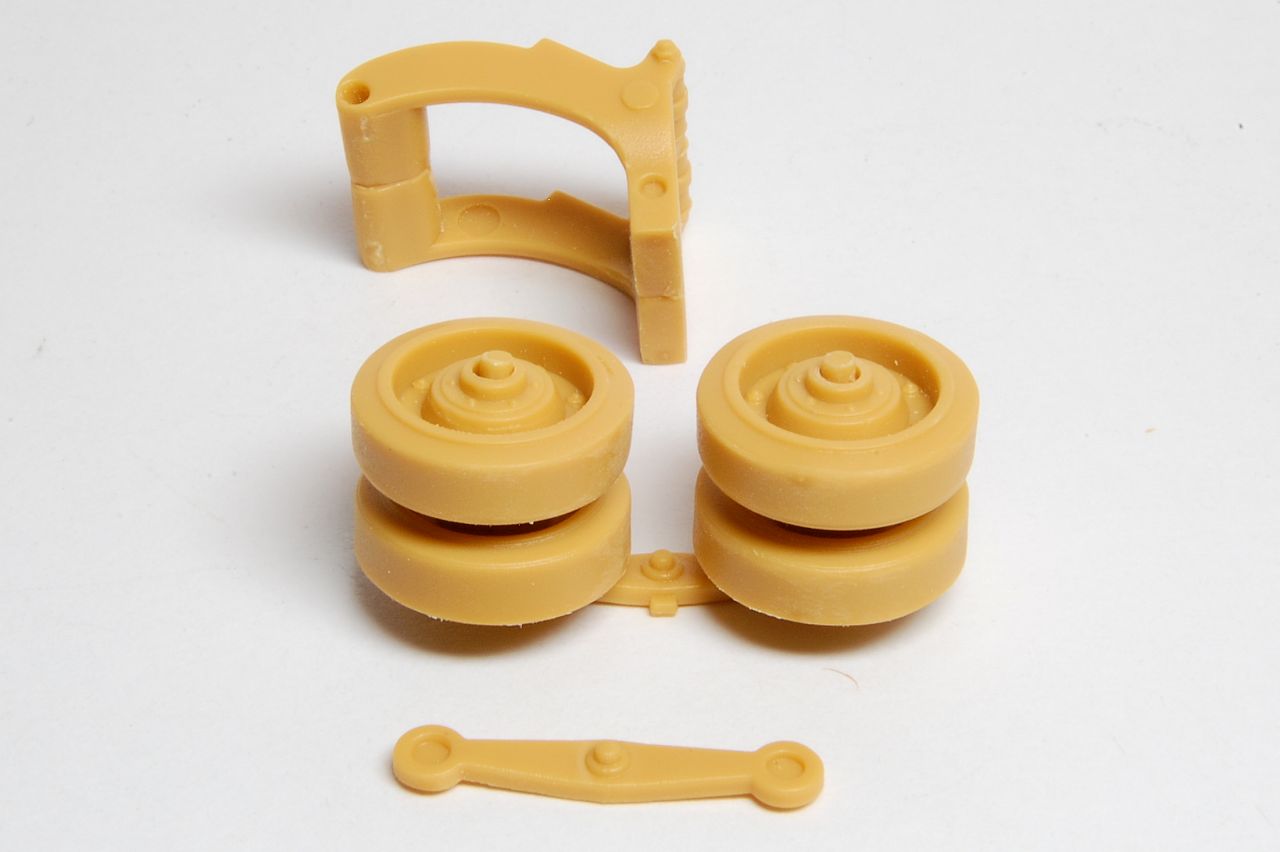
So we're building four of each assembly above, and these are the parts for one of them:
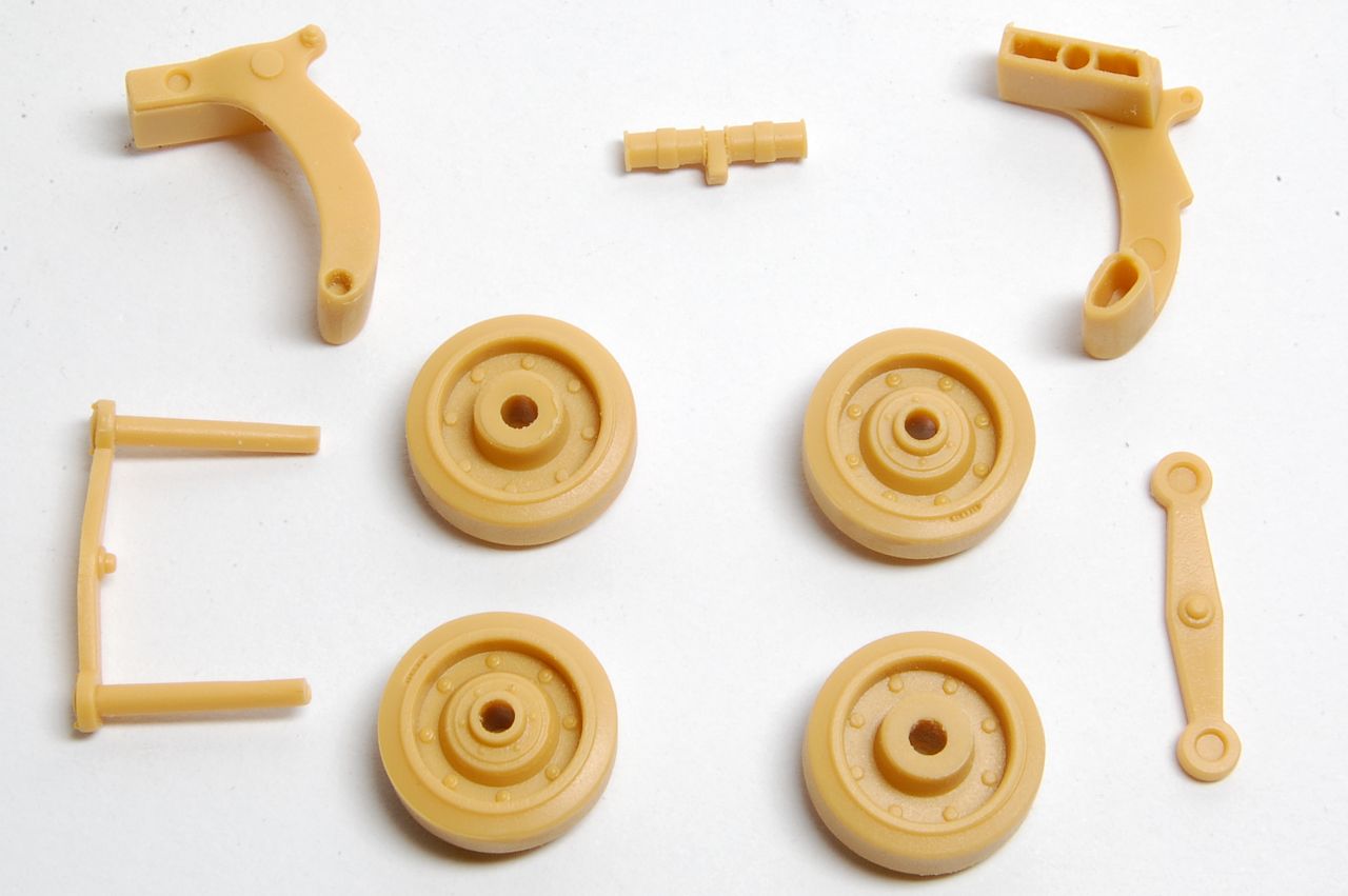
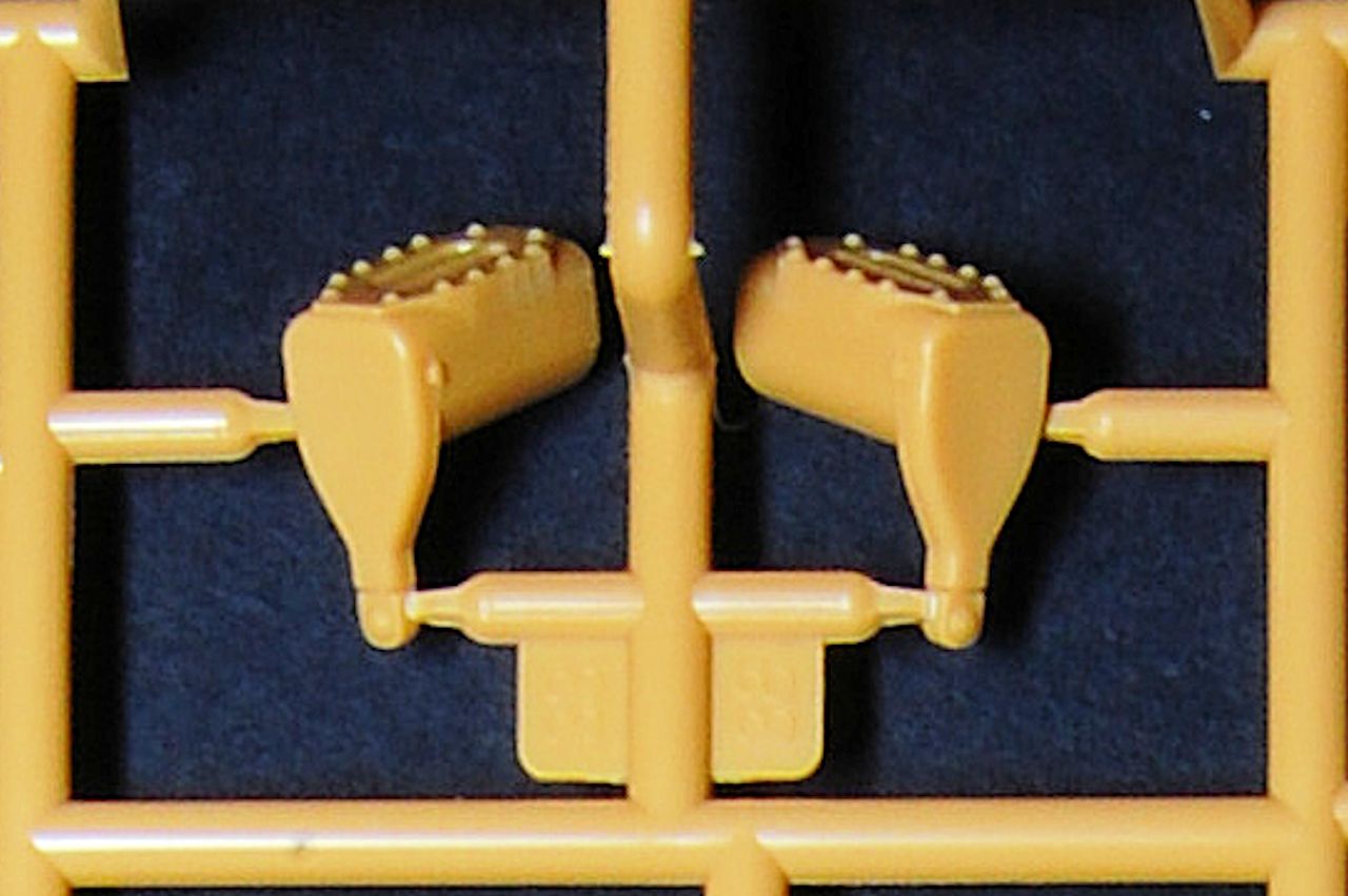
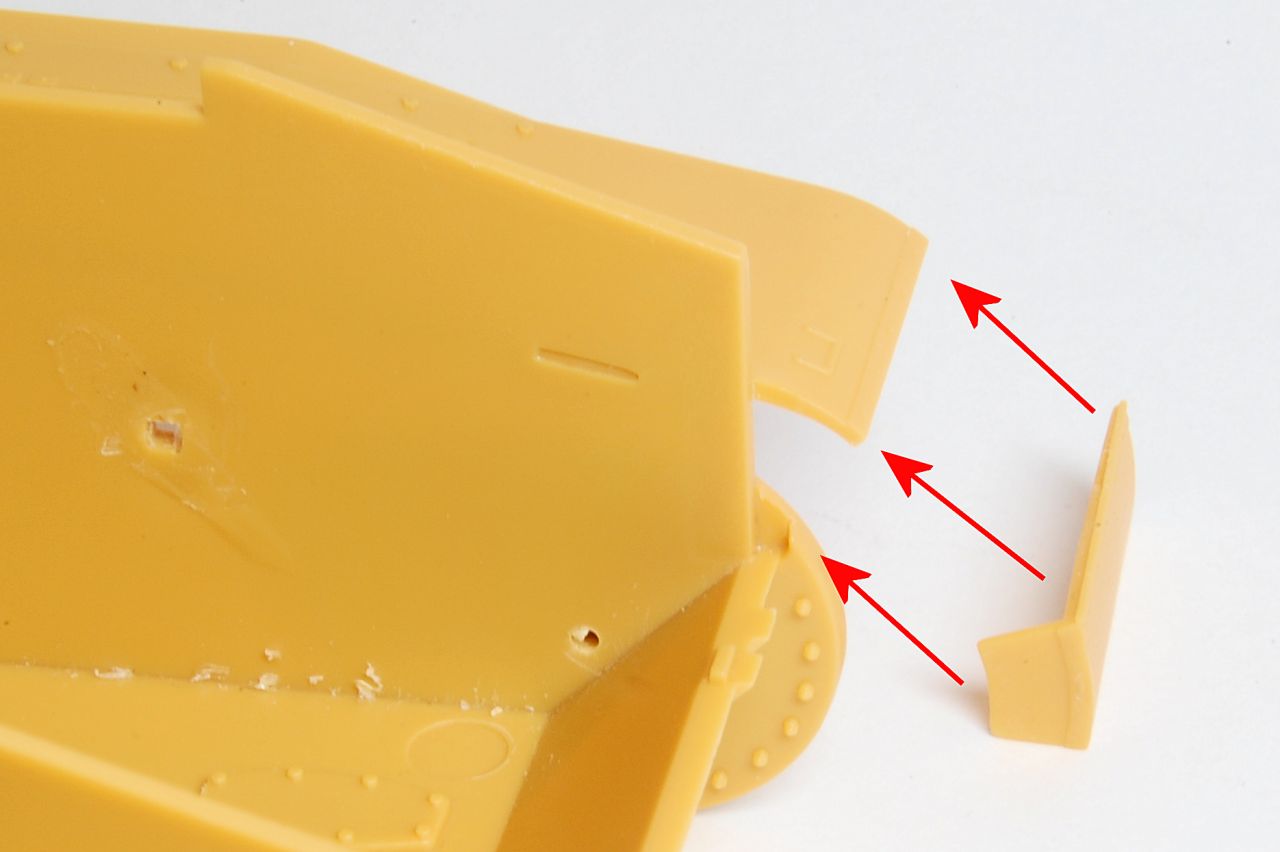
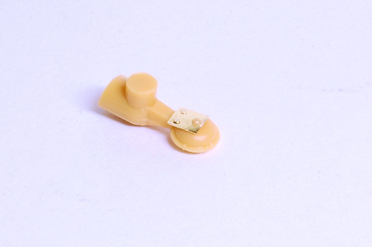
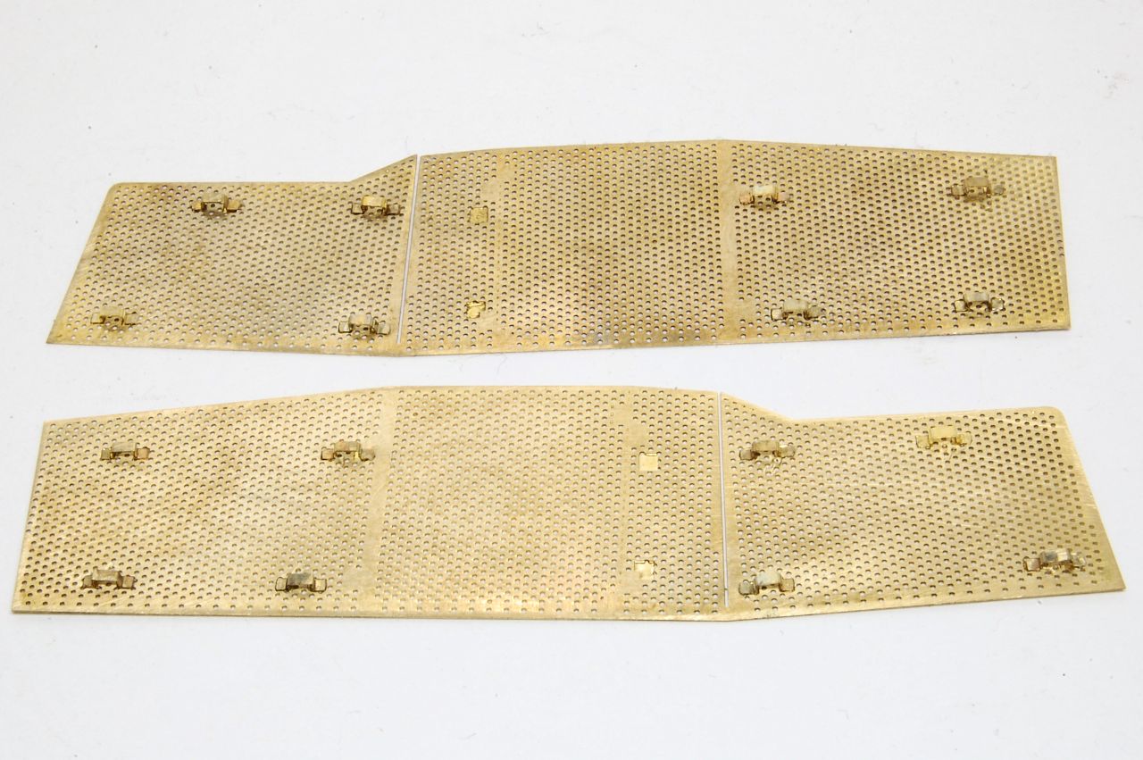
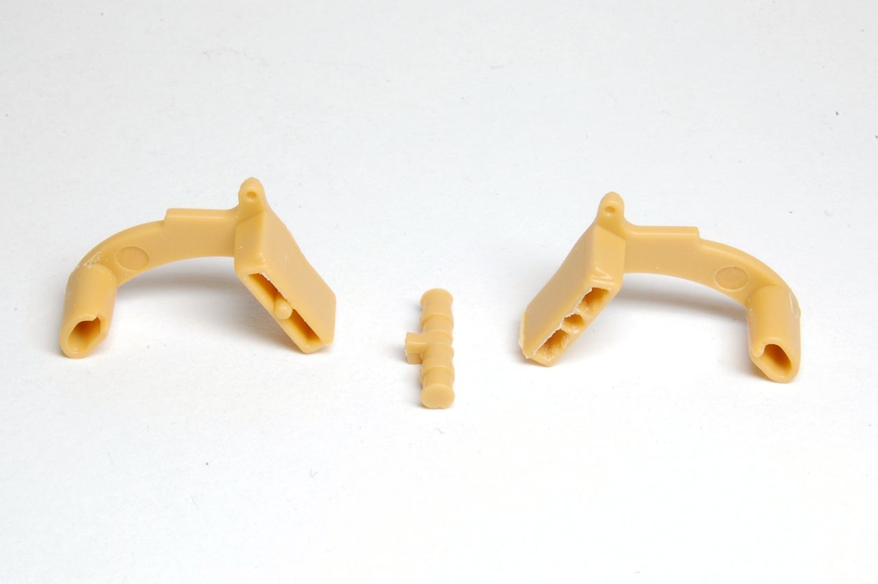
Below, left and right, are the halves of the swinging arms that allow each pair of wheels to articulate. These are pairs of C7 and C8, or C9 and C10; after careful study I concluded there is no difference between C7 and C10 or C8 and C9, so no need to keep track of which is which.
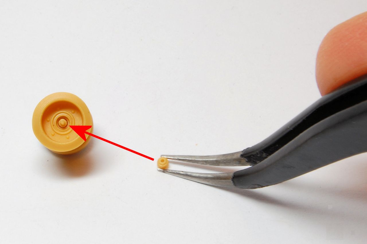
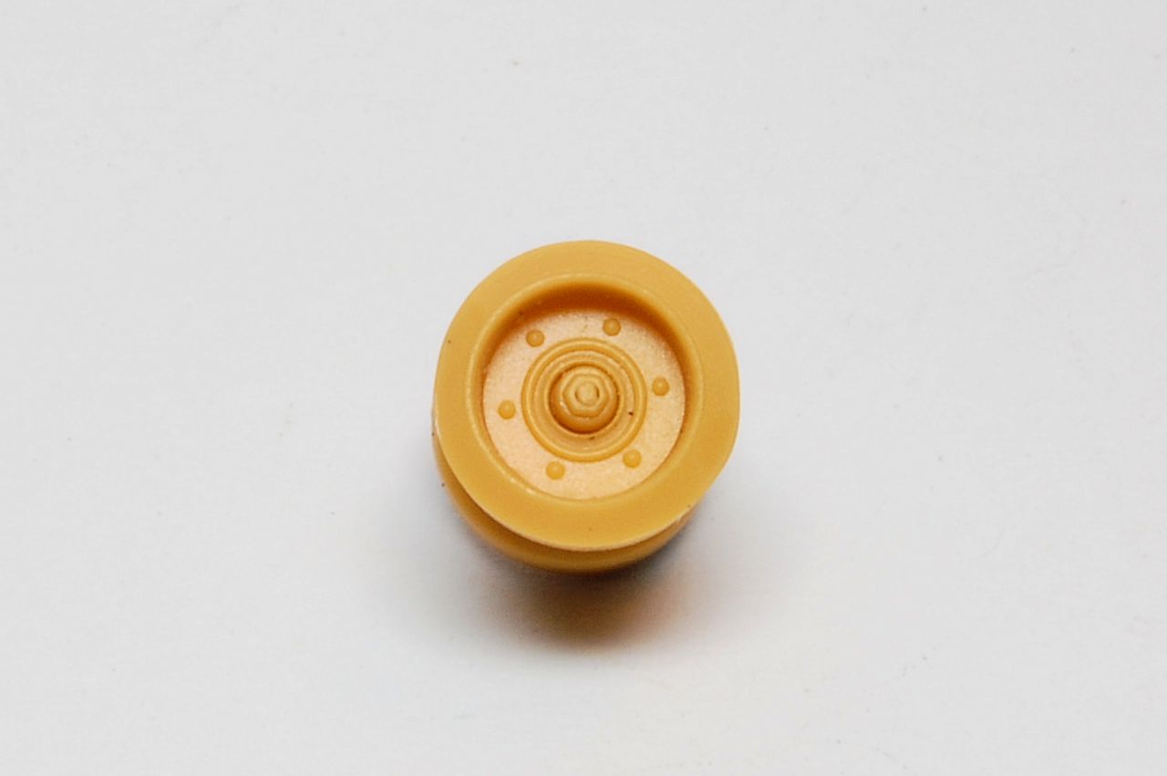
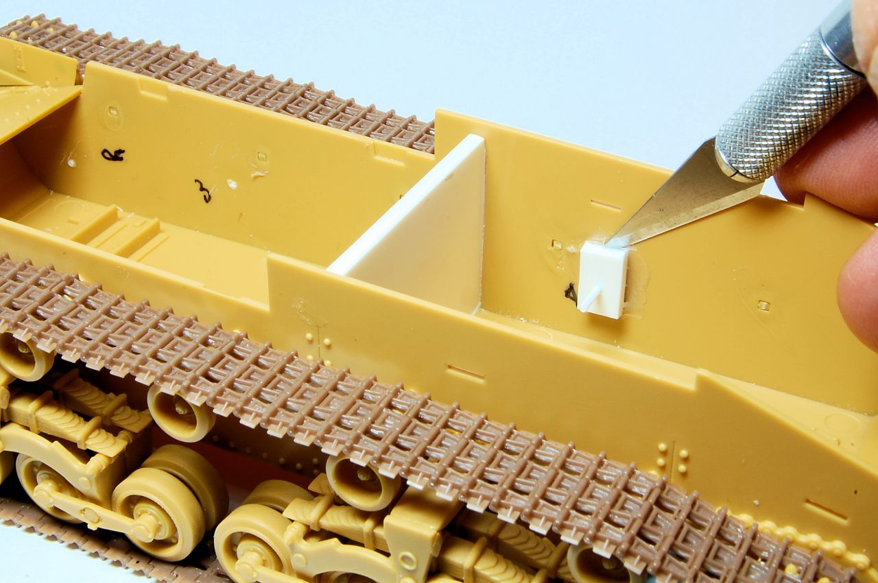
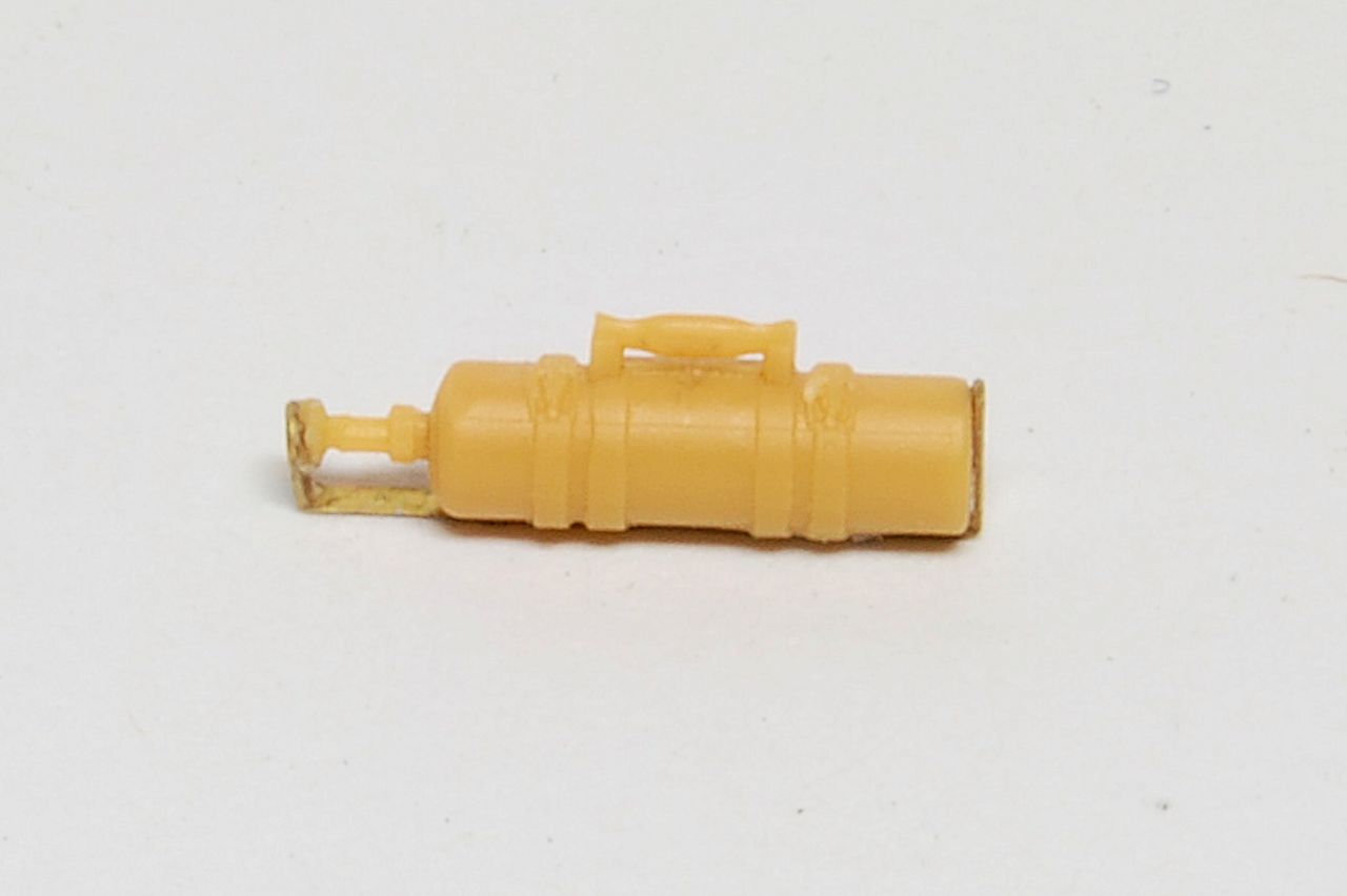
The thing in the middle is a sleeve through which the halves would be bolted at the top outer edge, and notice there are no pips on the ends to fit into the holes which the instructions suggest are there:
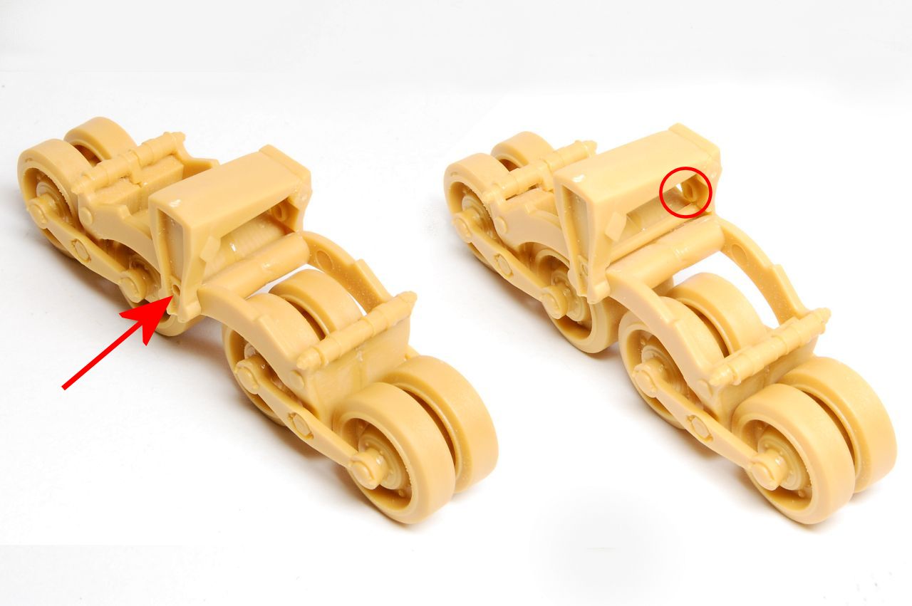
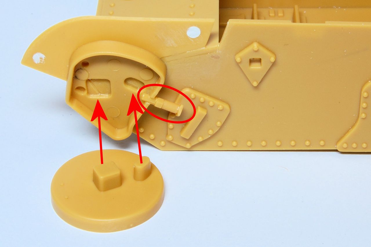
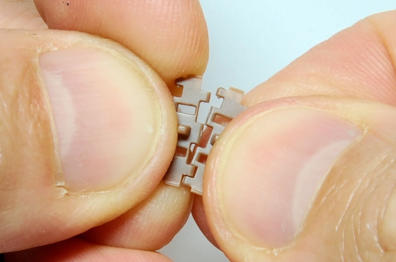
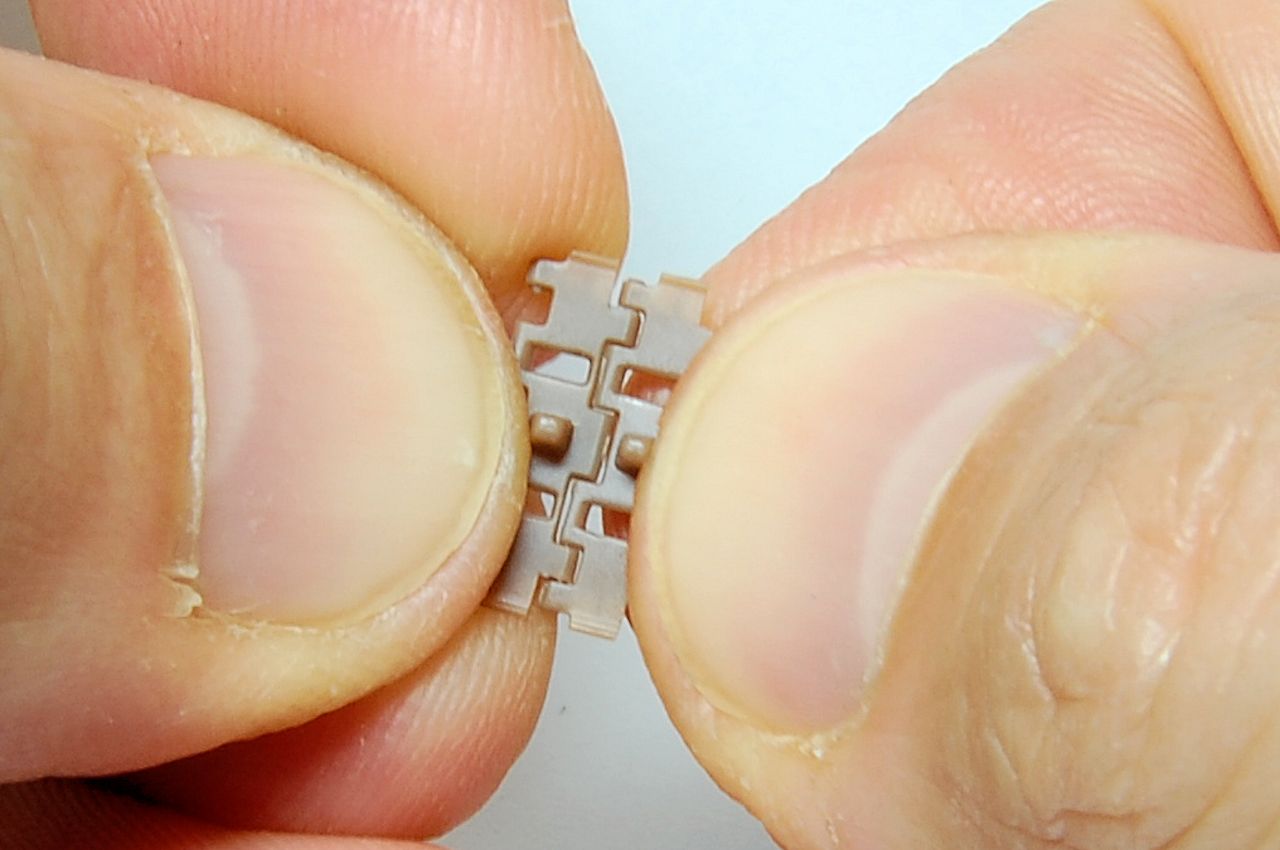
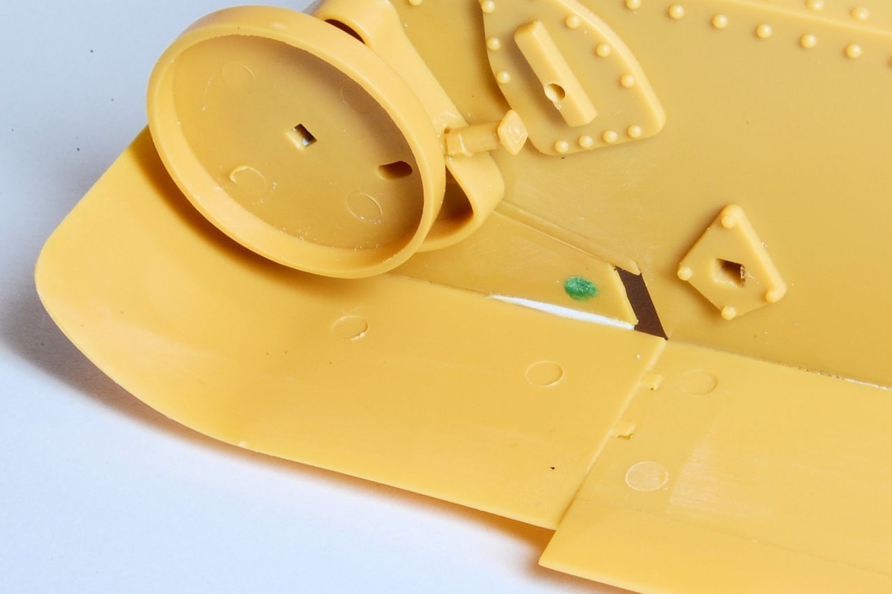
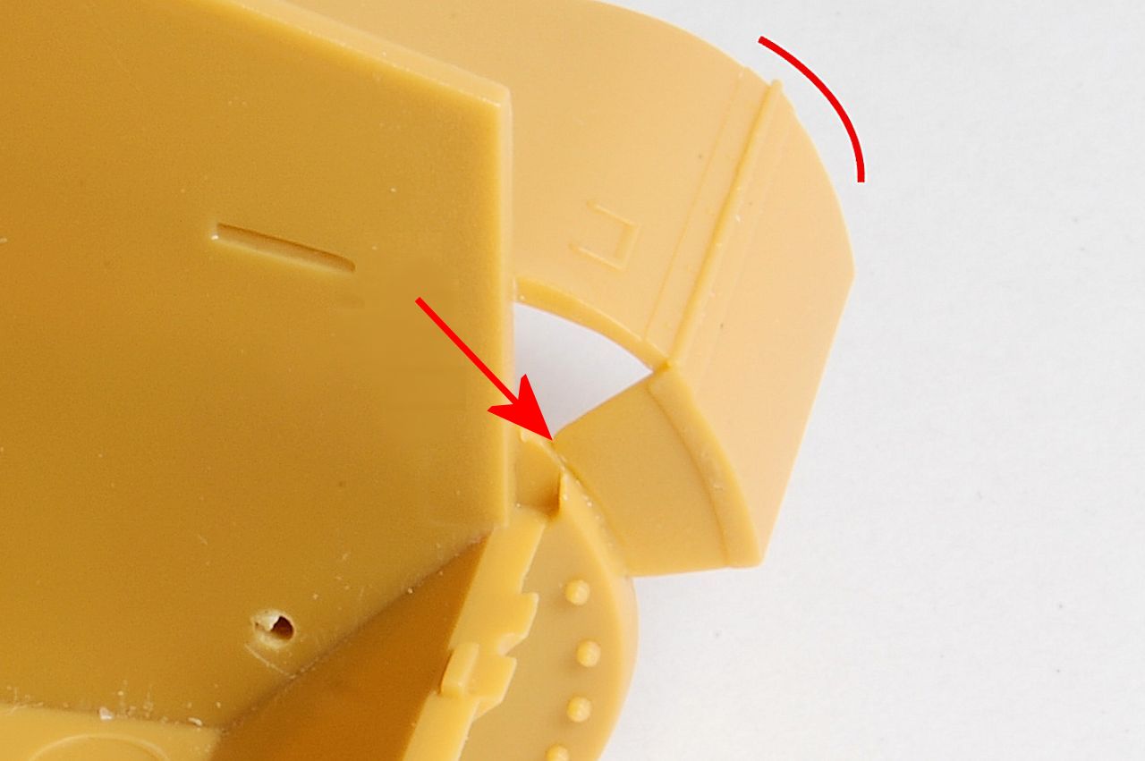
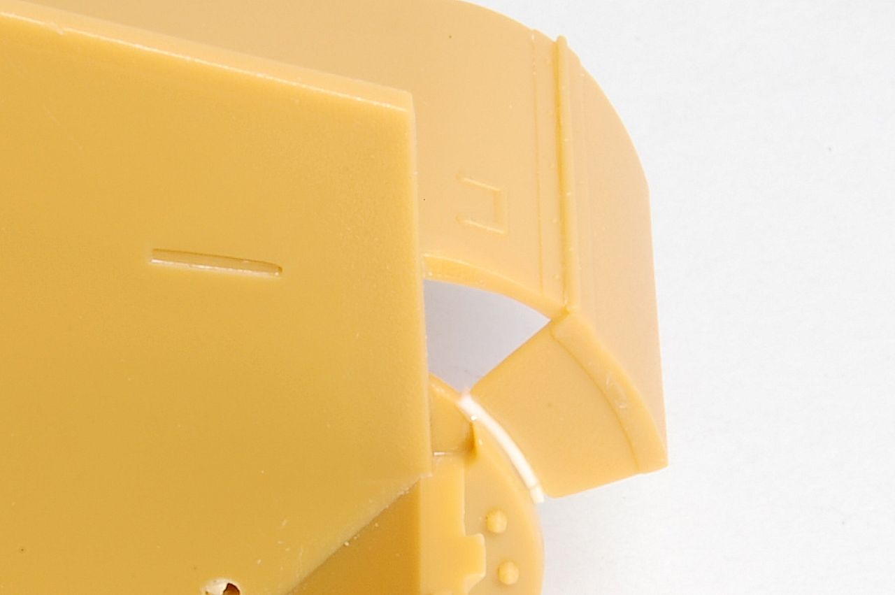
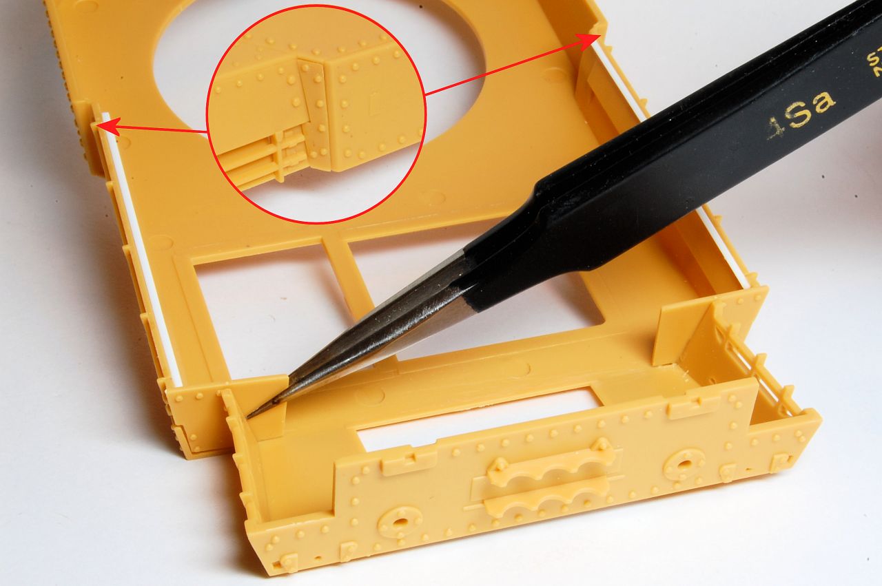
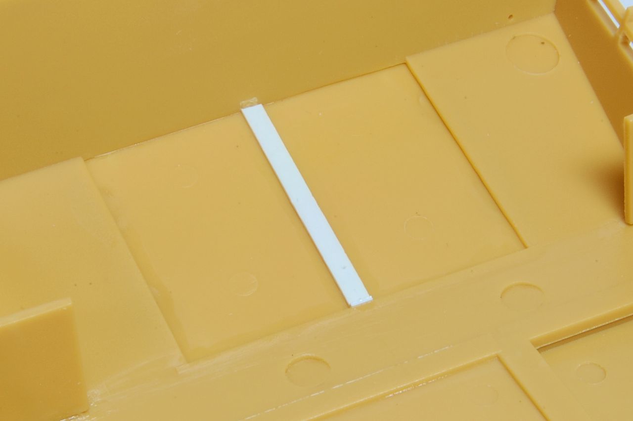
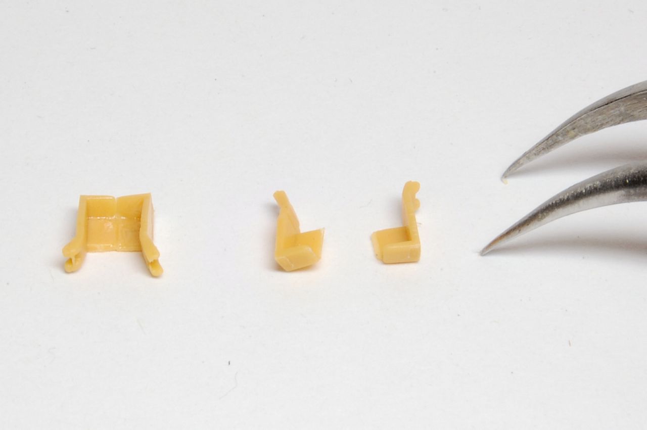
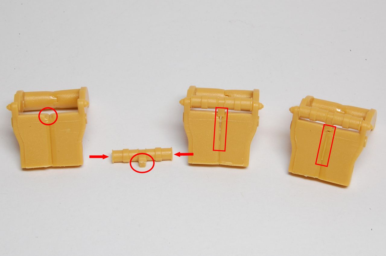
In the photo below we see the swinging arms during assembly. On the left is one joining together perfectly, with a little slot ringed, into which the little peg in the centre of the sleeve, ringed, fits. When that's done, a bit of a gap opens up at the top as the sleeve is slightly wider than the space it fits into. I think the groove down the middle is OK as it represents two castings bolted together, but we don't really want a gap, so on the right it's been filled with a sliver of sprue.
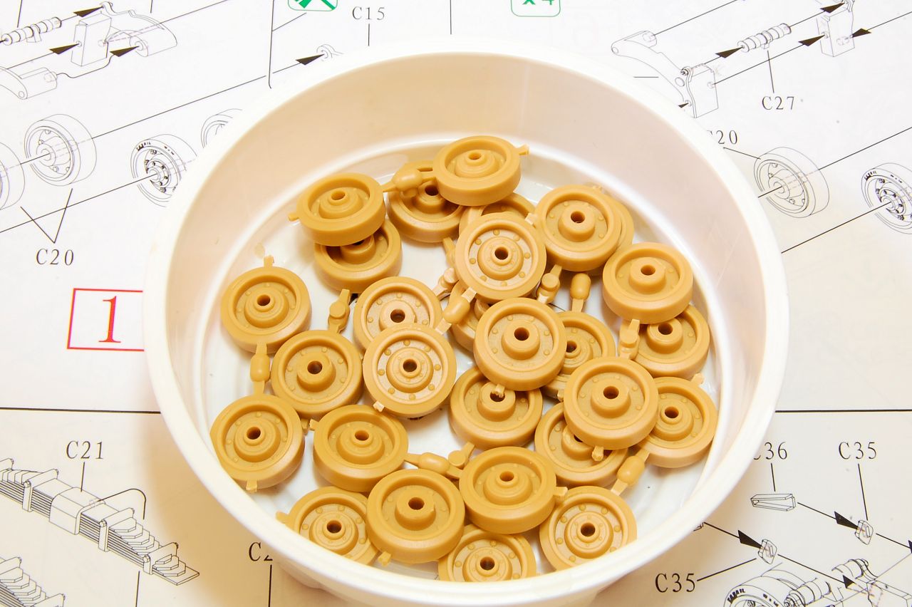
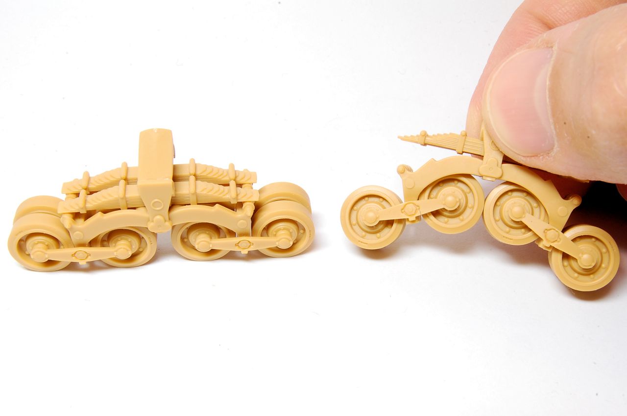
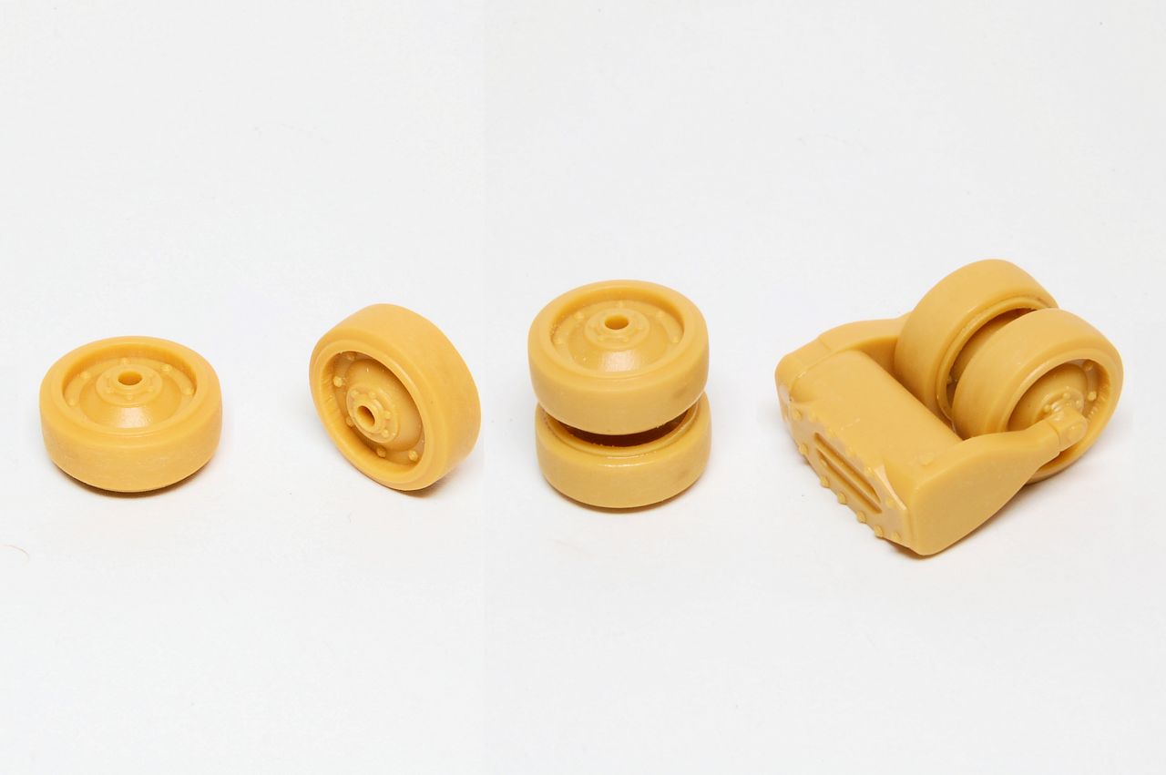
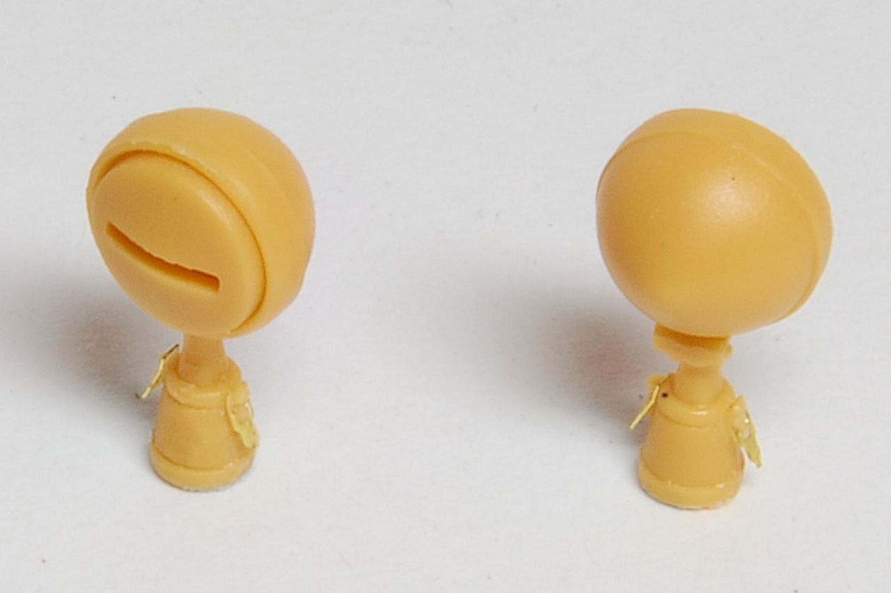
Having made eight of those and put them aside to set, I took four wheels and made two pairs:
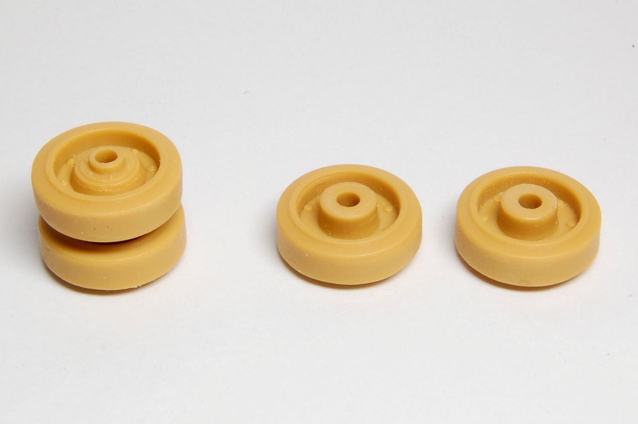
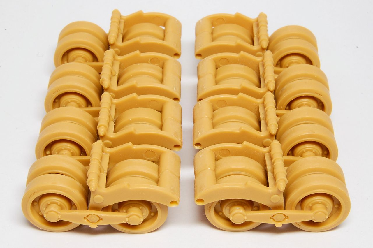
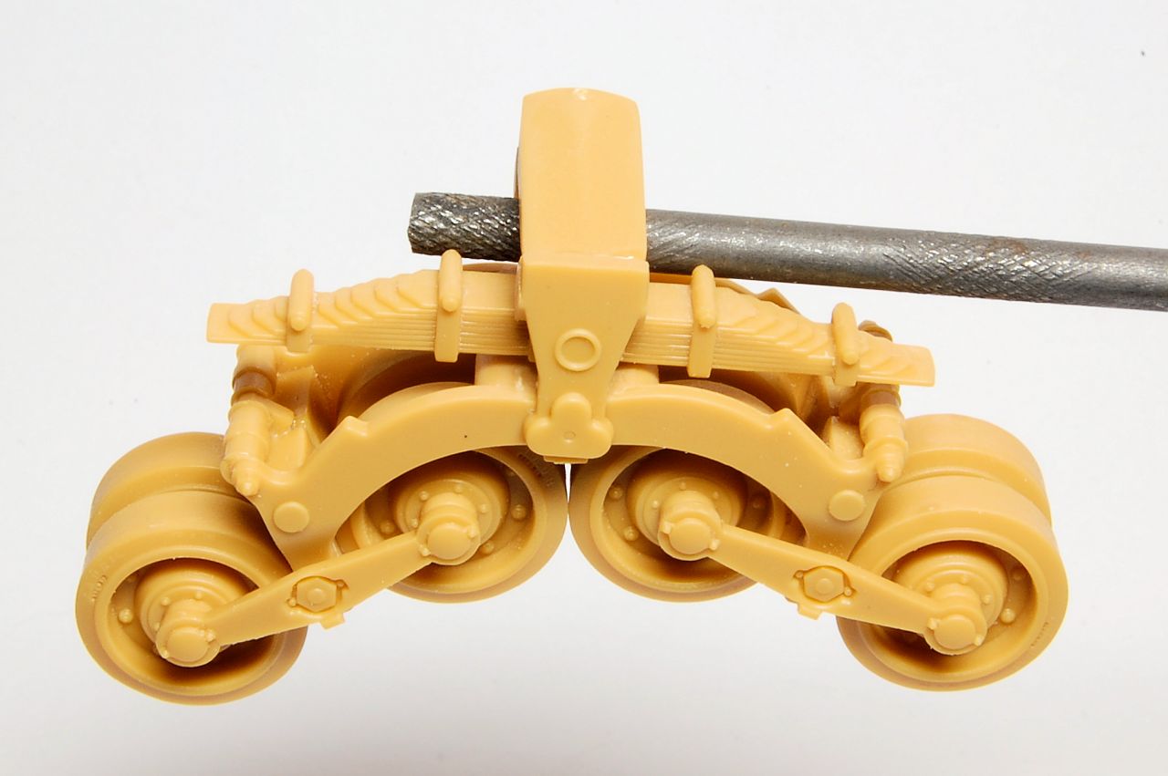
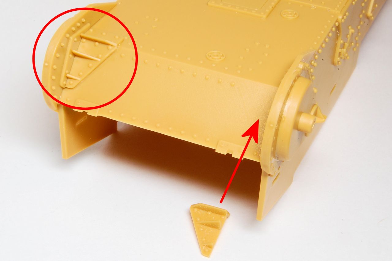
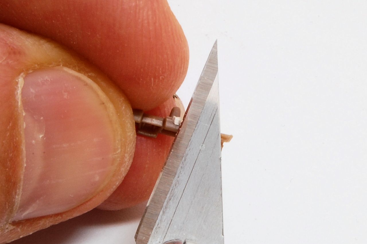
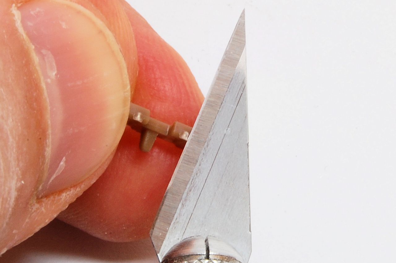
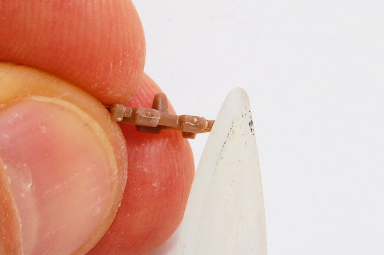
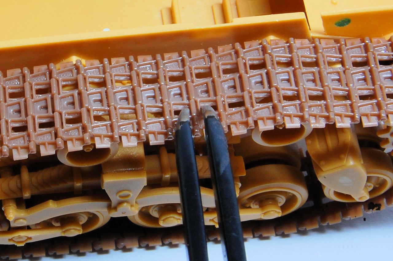
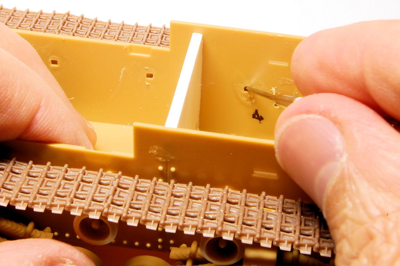
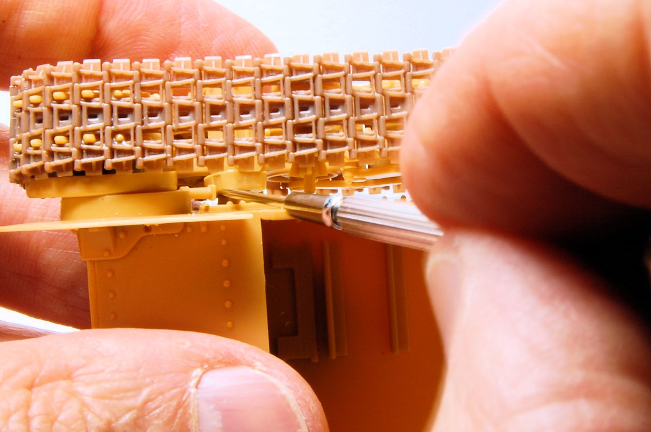
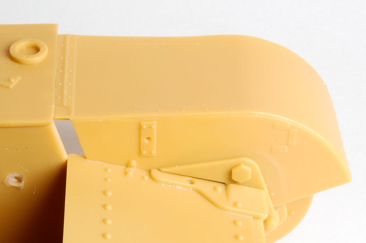
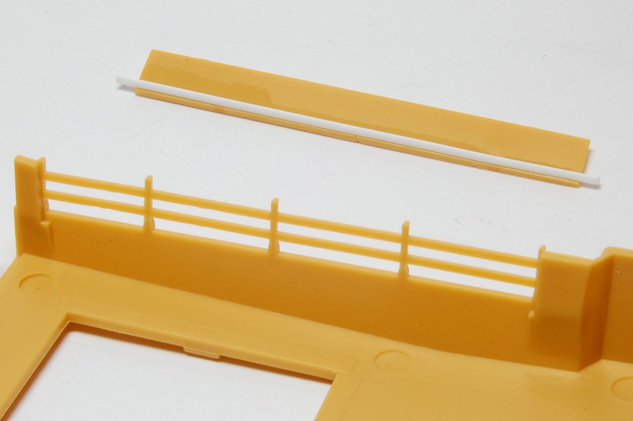
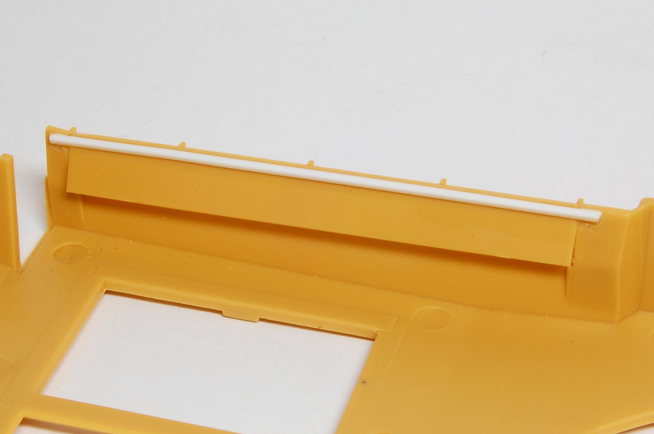
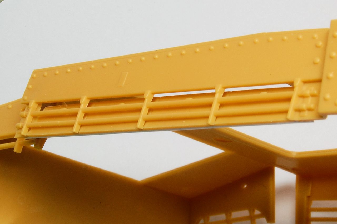
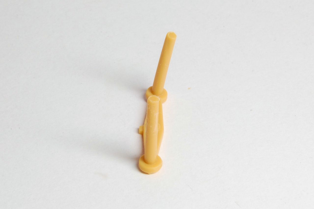
The pairs of wheels are mounted on the swinging arms by two connected axles. As is common with long components moulded this way, many of them were a bit bent (as below) and needed to be twisted straight; one was snapped and had to be glued.
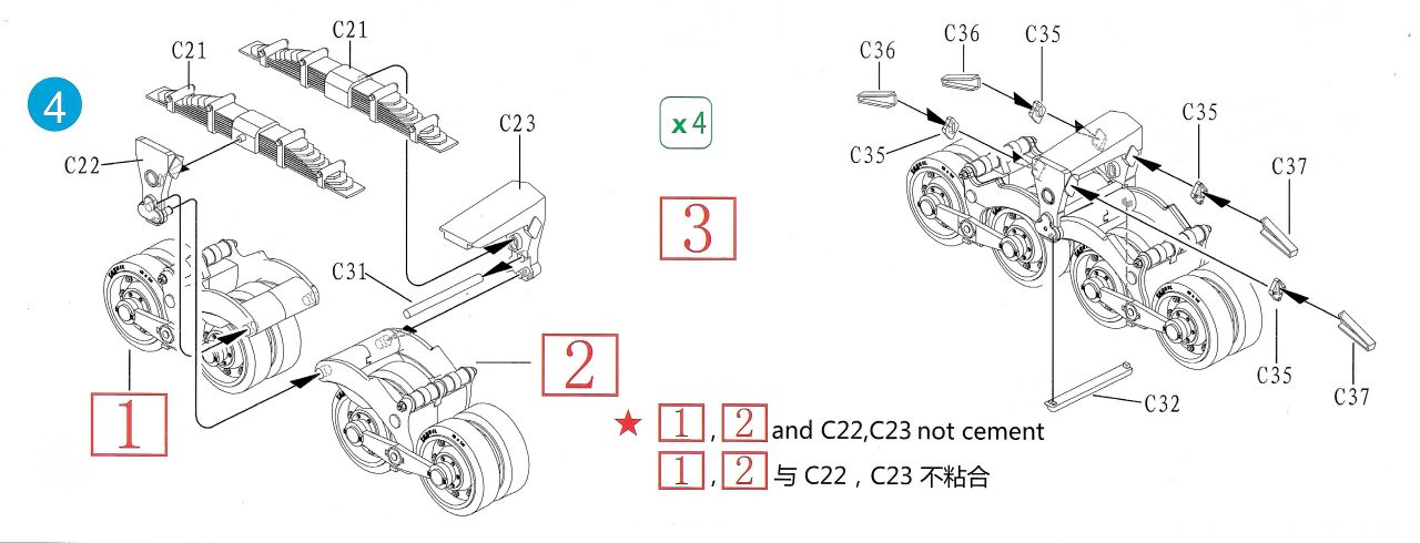
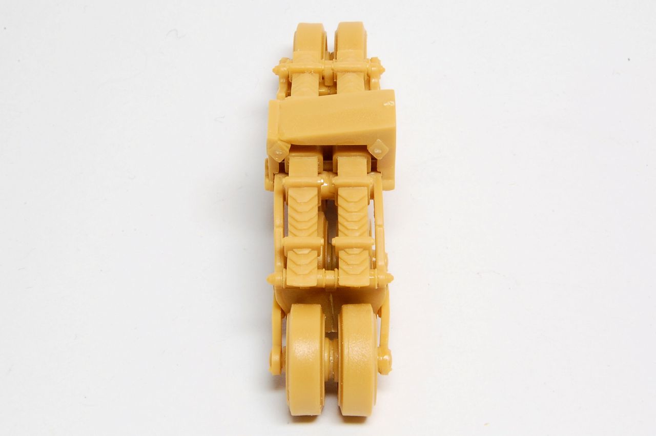
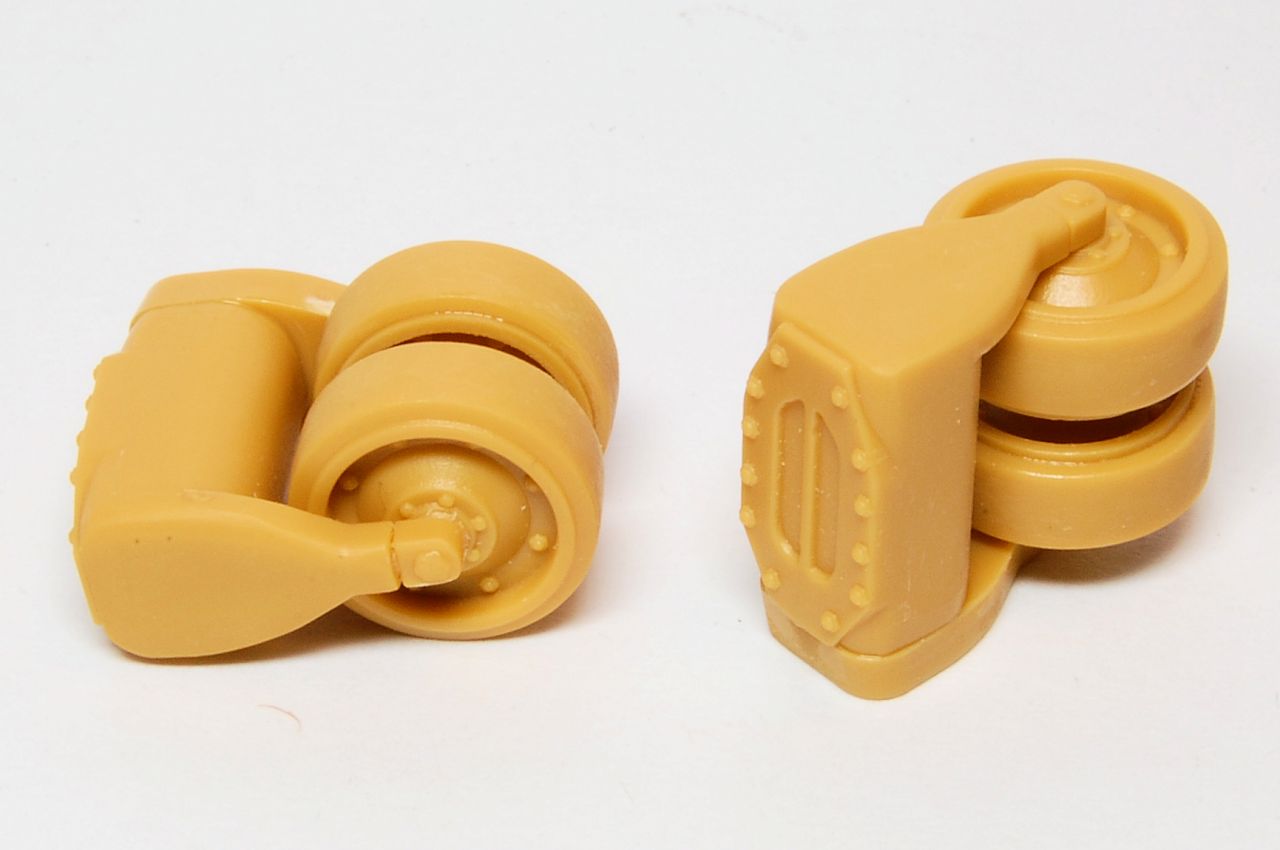
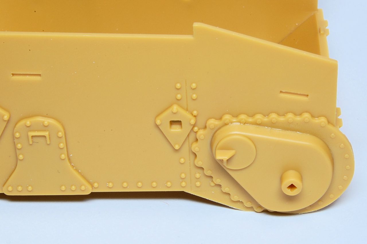
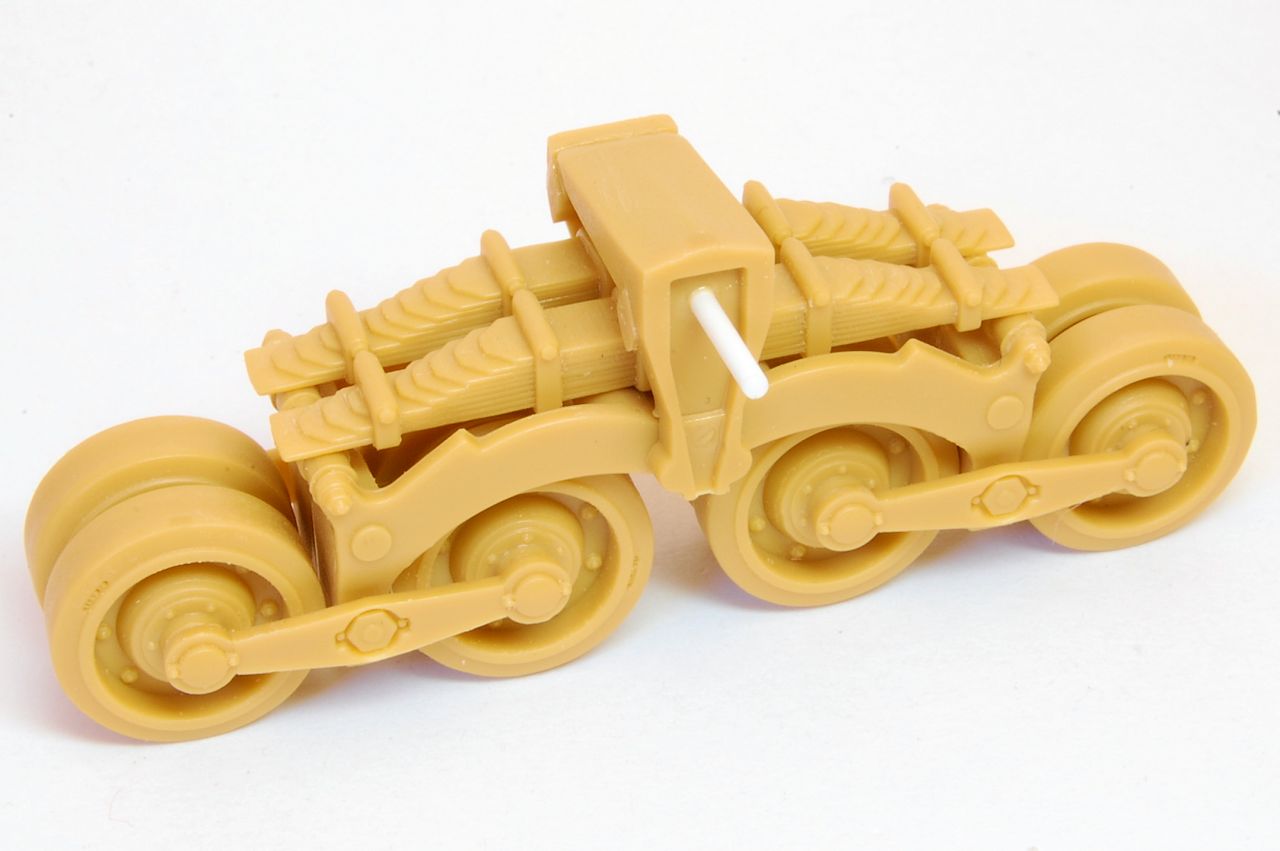
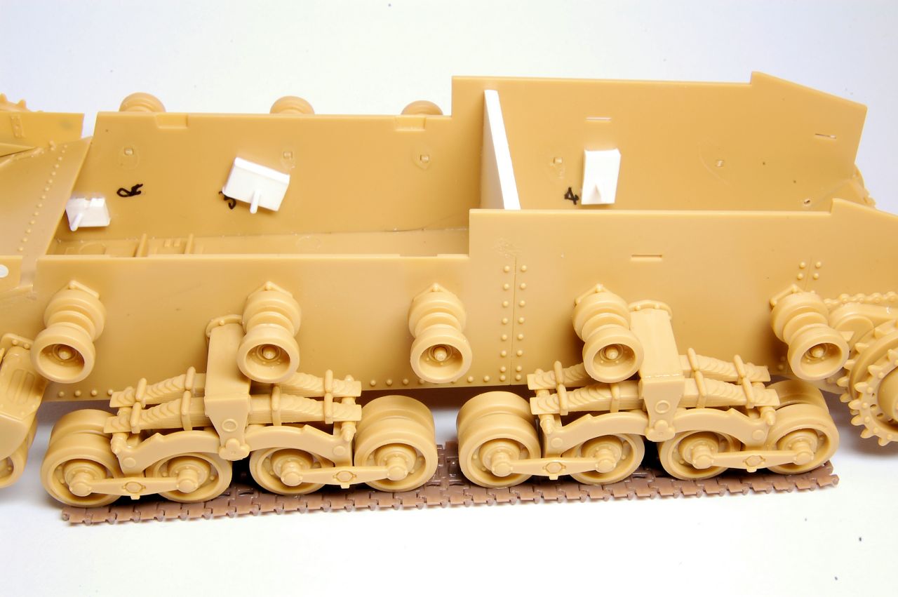
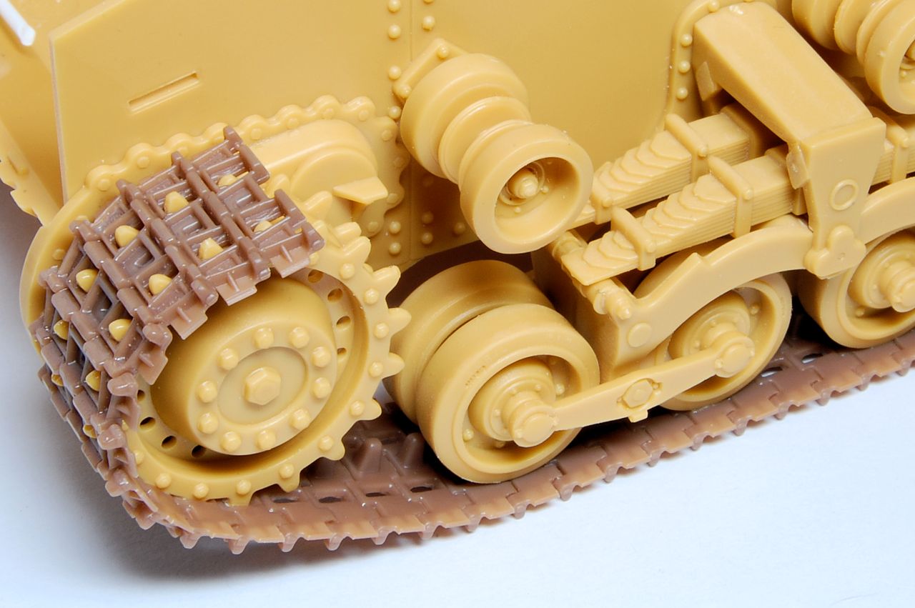
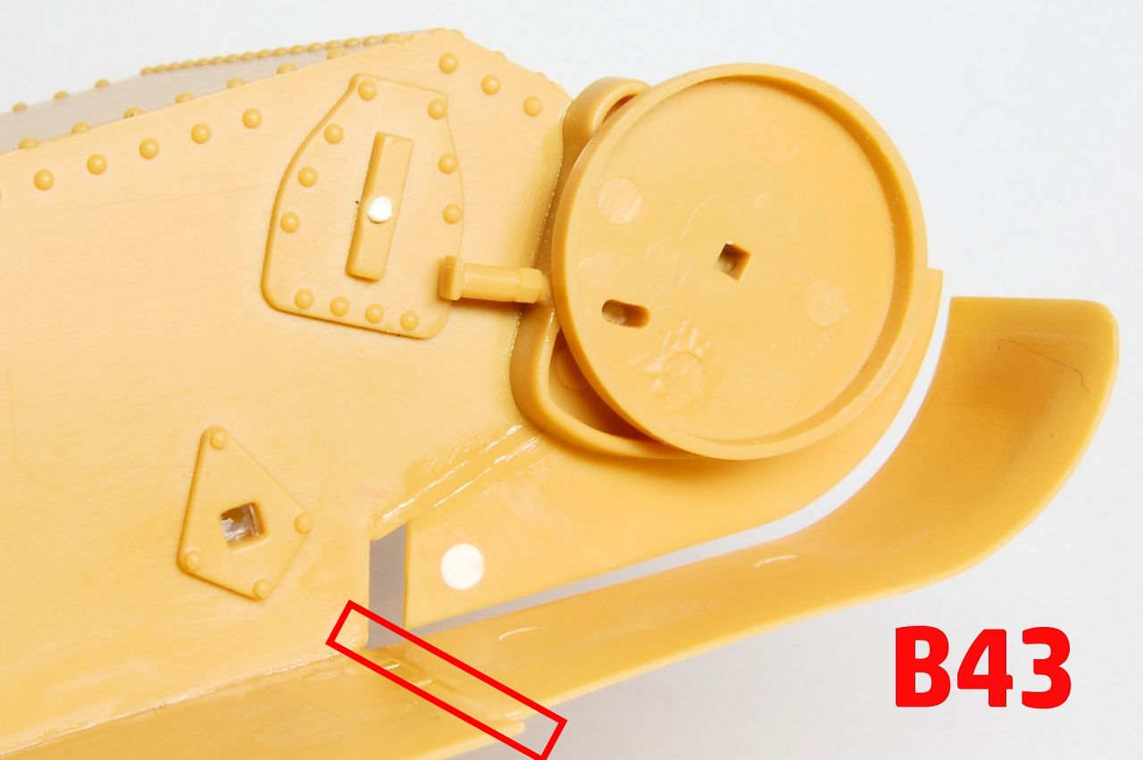
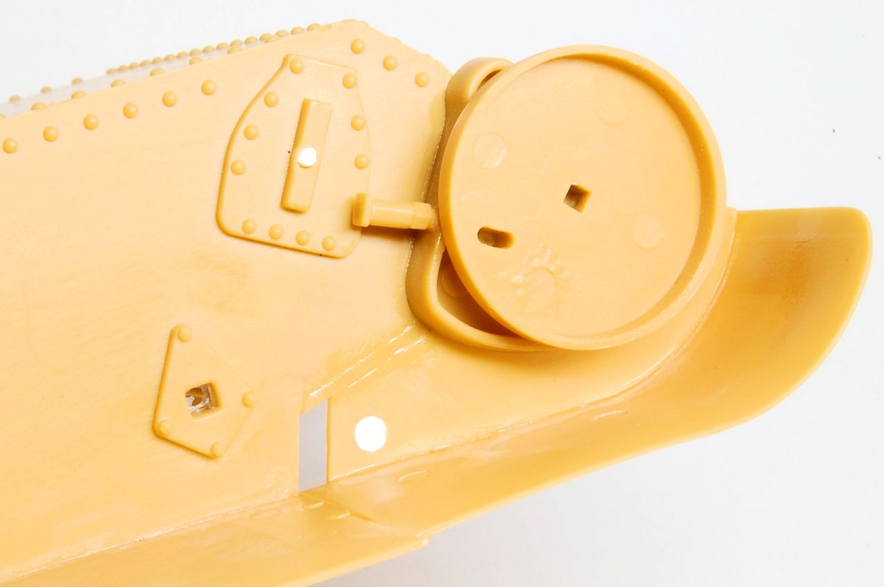
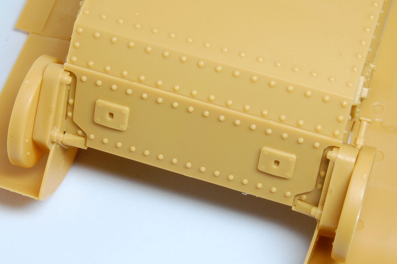
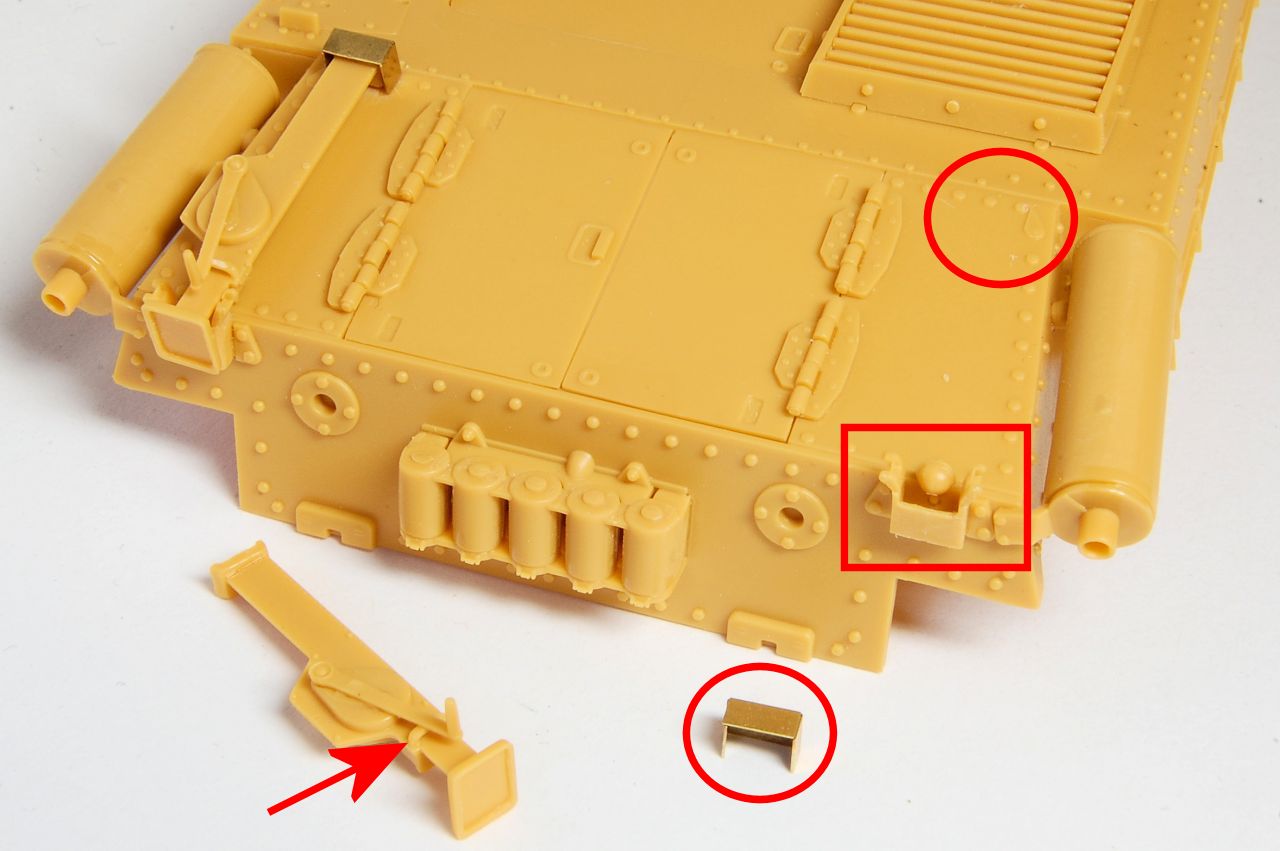
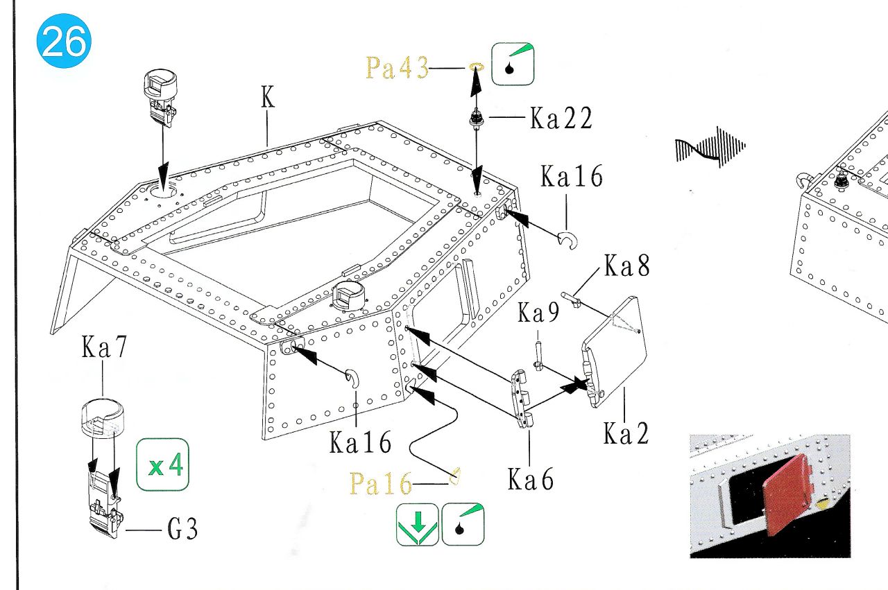
Here's two wheel pairs mounted on the axles, the swinging arm ready to fit on to the pip in the centre of the outer axle brace, and the inner axle brace at the front.
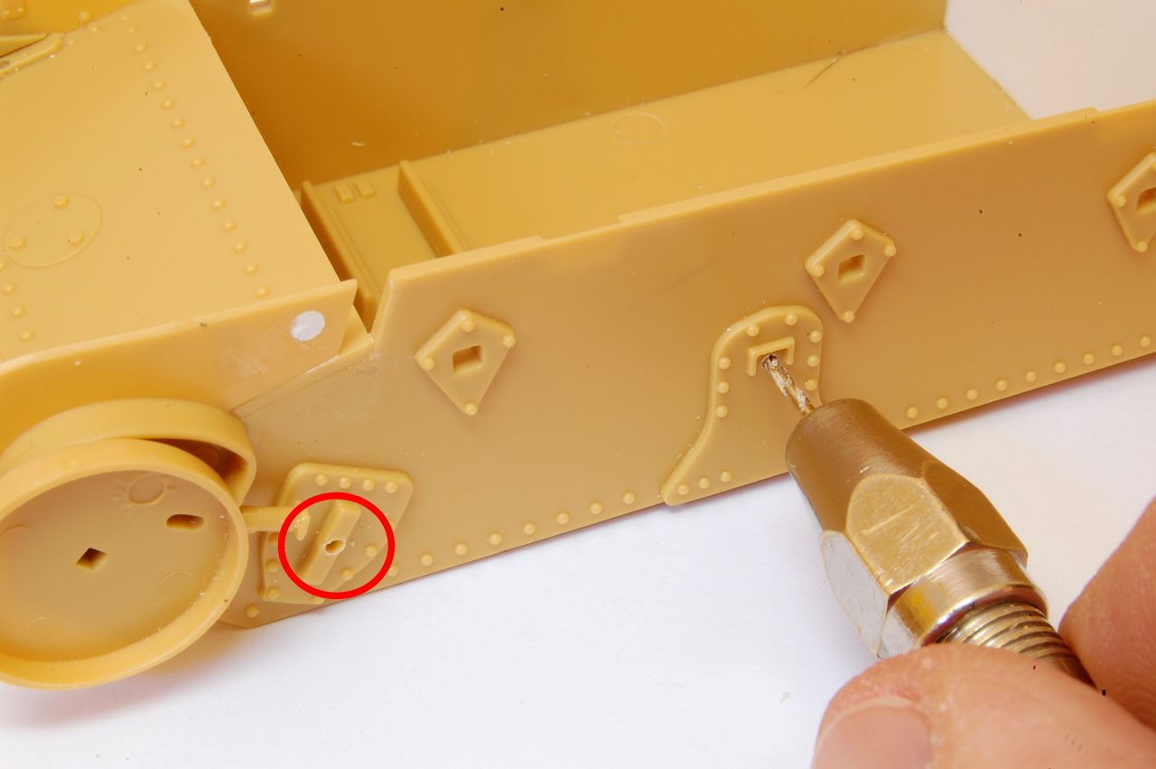
Note the outer brace (it is lying outer face down) has a small square hanging off the bottom of the centre, while the inner brace doesn't. This is how you will tell which way round the assembly will mount on the rest of the bogie assembly, and in fact this is the key to the difference between 3/1 and 3/2 in the instruction steps - it's which way around the swinging arms are oriented in relation to this outer brace.