Constructive Feedback
For in-progress or completed build photos. Give and get contructive feedback!
Sherman M4A1 "Major Jim" Build
exer
Visit this Community
Dublin, Ireland
Joined: November 27, 2004
KitMaker: 6,048 posts
Armorama: 4,619 posts
Posted: Thursday, August 09, 2012 - 08:53 AM UTC

Quoted Text

No worries. It's still fixable. I'm fabricating the bump!


I can't see the bump
terrybarrett
Visit this Community
North Carolina, United States
Joined: November 20, 2010
KitMaker: 195 posts
Armorama: 180 posts
Posted: Thursday, August 09, 2012 - 10:03 AM UTC
That looks like a light colored bump to me. The antenna is on the photographer's side of the open driver's hatch. There would have to be some sort of protrusion for the antenna mast to mount vertically? Maybe I'm losing it? Is it mounted right by the hatch? That would be easier than fabricating a bump!!
PantherF
Visit this Community
Indiana, United States
Joined: June 10, 2005
KitMaker: 6,188 posts
Armorama: 5,960 posts
Posted: Thursday, August 09, 2012 - 11:28 PM UTC
Isn't the fan located inside the hull? So an antenna mount could still be mounted on the outside of the armored cover. I know the Shermans used in the making of Kellys Heroes had them mounted there as well, so maybe the fan was removed and or inoperative?

Very nice project Terry.


~ Jeff
SdAufKla
Visit this Community
South Carolina, United States
Joined: May 07, 2010
KitMaker: 2,238 posts
Armorama: 2,158 posts
Posted: Friday, August 10, 2012 - 03:26 AM UTC
This is all very curious...

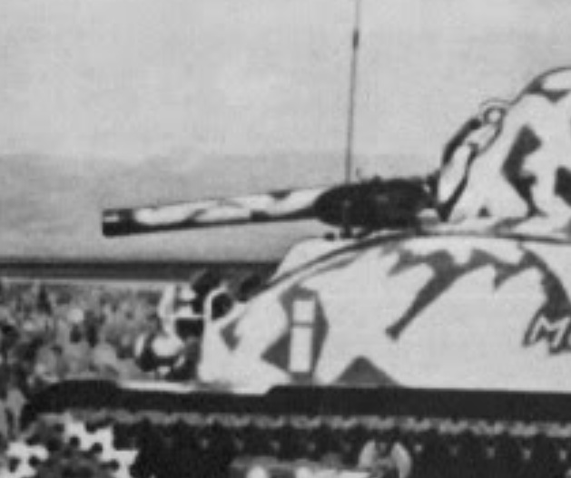
When I first started reading this thread, I thought the answer was probably pretty simple: The ventilator was most likely un-installed, the "mushroom" shaped cover was removed and replaced with the flat circular antenna base mount from an M4 hull (same size and bolt hole layout as the M4A1 hull ventilator cover). This seemed to be the most logical and straight forward solution. There would have been a ring under the flat circular cover, but it would have been easy and fast to do - all screw or bolt on-off exchangable parts.

However, the above photo seems to clearly show that the antenna was mounted on the DRIVER'S side of the hull front instead of the bow gunner's side. This makes the entire ventilator issue moot. The ventilator is on the bow gunner's side, not the driver's.

In the photo, the antenna base appears to be in the foreground in front of the hatch and the antenna in front of the gun barrel. To me the antenna looks like it's on the driver's side. The mounting area almost looks like the hull antenna "bump" from an M4.

If this was the case (as it seems to have been) then it's very hard to understand why.

The driver was surely too busy to also do double duty as the HQ radio man. There's no room right next to the driver to mount the SCR-506 radio, and if it was put on his side, then he would have had to almost turn around in his seat to reach it. This positioning makes the whole idea of the radio on the driver's side even harder to imagine.

If the radio was mounted in its usual position next ot the bow gunner, then why wasn't the antenna also on that side? If the unit maint folks were going to go through the trouble of welding (as it appears) some sort of spacer to mount the antenna base to, as well as, drilling a hole through the hull for the coax wire, why not do all of that on the bow gunner's side?

At the very least, it seems to me that the coax cable would have had to be routed across the inside of the hull roof from the bow gunner's side to the driver's side, but why go to all that trouble? Could there have been a static suppression issue with the electric ventilator fan motor next to the bow gunner causing radio interference? (The only thing that I can think of.) If so, why not simply disconnect the power to the fan or, even simpler, not turn it on?

Another possible answer could have been that the loader worked as the HQ radio man, but then he would have had to try to operate the SCR-506 in the hull side through the turret basket and couldn't have worked it at all if the turret was traversed. This seems even more improbable than the driver working the radio.

Did they just torch off the hull antenna mount from an M4 and weld it onto the M4A1 hull in the only place it could fit - next to the driver's hatch? This would have allowed retaining the hull ventilator next to the bow gunner and to install a hull antenna. Hmmmm...

So, what was up with "Maj. Jim"? Am I missing the obvious here?

Like I said, all very curious to me...

terrybarrett
Visit this Community
North Carolina, United States
Joined: November 20, 2010
KitMaker: 195 posts
Armorama: 180 posts
Posted: Friday, August 10, 2012 - 03:53 AM UTC
Thanks for the thoughtful reply Mike. I am leaning toward your final option, just attached slightly forward and slightly left of the drivers hatch. It would interfere with the hatch fully opening but based on that photo I don't see any other option.
pseudorealityx
Visit this Community
Georgia, United States
Joined: January 31, 2010
KitMaker: 2,191 posts
Armorama: 1,814 posts
Posted: Friday, August 10, 2012 - 03:55 AM UTC
You know....

The thing 'we' are seeing as the base of the antenna might just be the reflection from the angled armored flap of the periscope on the driver's hatch. Could it just be a great coincidence that it lines up perfectly with the antenna behind?
terrybarrett
Visit this Community
North Carolina, United States
Joined: November 20, 2010
KitMaker: 195 posts
Armorama: 180 posts
Posted: Friday, August 10, 2012 - 03:58 AM UTC
The more I look at it the more I think it is just mounted on the horizontal area that surrounds the drivers hatch. When i hold up my hull at that angle the "jut out" for the drivers hatch matches the shape/contour in the picture. It's tight bit it fits!

SdAufKla
Visit this Community
South Carolina, United States
Joined: May 07, 2010
KitMaker: 2,238 posts
Armorama: 2,158 posts
Posted: Friday, August 10, 2012 - 06:33 AM UTC

Quoted Text

The more I look at it the more I think it is just mounted on the horizontal area that surrounds the drivers hatch. When i hold up my hull at that angle the "jut out" for the drivers hatch matches the shape/contour in the picture. It's tight bit it fits!


Could be.

Maybe check and see if the hatch will still open and hold at the same angle as in the photo without touching the antenna.

Looking at some reference photos, it doesn't seem like there's enough room between the edge of the hatch combing and the outter edge of the cast hatch bulge to fit the antenna mount and still have the hatch open past the vertical.

I wouldn't rule out Jesse's observation about the whole thing being an optical illusion, but the part that looks like an antenna base does look to me like a cylinder and there's that little "open" spot to its bottom rear in the photo. I could go with the optical illusion idea except for that spot which suggests to me that the "antenna" base is not the cover for the periscope on the hatch.

(Also, the SCR-506 antenna base, MP-37 (or -57) is different than the one that Terry's using (MP-48). It's more regularly cylindrical shaped to include the spring. Google the terms Mp37, Mp57, and Mp48 for images.)

If you really want to get some hard corps Sherma-holics looking at this, you might consider posting a question in the Allied forums on Missing Lynx. I tried a brief search there using the term "Major Jim," but no luck. However, if anyone else has ever looked seriously at this issue, you're likely to find him there.

Great build, though. Just goes to show you never know where the research will take you...

Good luck!
Plasticat
Visit this Community
Idaho, United States
Joined: September 03, 2003
KitMaker: 448 posts
Armorama: 245 posts
Posted: Friday, August 10, 2012 - 09:29 AM UTC
Could it be....that the base of the antenna, as seen in the photo, is actually the periscope top on top of the hatch? It seems to be in the correct spot for the periscope, especially if the inside portion of the scope is tilted to the rear. Granted the photo is not clear, but it does seem to be tilted to the rear. It wouldn't be the first time that two completly different items lined up in a photo and made for an optical illusion. Anyway, I am intrigued!
AgentG
Visit this Community
Nevada, United States
Joined: December 21, 2008
KitMaker: 1,109 posts
Armorama: 1,095 posts
Posted: Friday, August 10, 2012 - 09:55 AM UTC
Since I started this fire storm, let me add a bit more. I think that's the co driver's hatch, on the right side. Look at the angle of the small tab protruding fron the top edge of the open hatch, then look at what resembles the bottom (inside portion) of the periscope. I think that the antenna is just to theright of the driver's hatch and thus between the hatches.

exer
Visit this Community
Dublin, Ireland
Joined: November 27, 2004
KitMaker: 6,048 posts
Armorama: 4,619 posts
Posted: Friday, August 10, 2012 - 10:04 AM UTC

Quoted Text

Since I started this fire storm, let me add a bit more. I think that's the co driver's hatch, on the right side. Look at the angle of the small tab protruding fron the top edge of the open hatch, then look at what resembles the bottom (inside portion) of the periscope. I think that the antenna is just to theright of the driver's hatch and thus between the hatches.


Between the hatches? Sorry that makes no sense at all- that puts it alomost right in front of the gun. Unlike some Commonwealth Command tanks "Major Jim" did not have a dummy gun
AgentG
Visit this Community
Nevada, United States
Joined: December 21, 2008
KitMaker: 1,109 posts
Armorama: 1,095 posts
Posted: Friday, August 10, 2012 - 10:11 AM UTC


G
SteveZaloga
Visit this Community
United States
Joined: August 10, 2012
KitMaker: 3 posts
Armorama: 3 posts
Posted: Friday, August 10, 2012 - 10:56 AM UTC
I just noticed this thread. I may not be infallible, but my model accurately depicts the location of the second radio on Major Jim. I corresponded with Col Gardiner years ago and have several photos of the tank from different angles. The second radio was mounted thorugh the right side vent opening as shown on my model. There's a historical photo of this from Col. Gardiner's collection in my Military Modelling article (Military Modelling, 1 Feb 2008 Vol. 38, No. 2, p21 bottom). It's not an especially wonderful photo, but it shows this feature fairly clearly. I'll try to upload it here.

http://i127.photobucket.com/albums/p160/szaloga/img150.jpg
ProfessorP
Visit this Community
Minnesota, United States
Joined: February 20, 2007
KitMaker: 339 posts
Armorama: 325 posts
Posted: Friday, August 10, 2012 - 11:21 AM UTC
I did a little manipulation of the image in Photoshop to see if I could enhance the contrast levels and sharpen the edges a bit. I don't know if this helps at all but it seems clearer to me that the antenna is in front of the hatch. Still not sure what that means for this discussion...


ProfessorP
Visit this Community
Minnesota, United States
Joined: February 20, 2007
KitMaker: 339 posts
Armorama: 325 posts
Posted: Friday, August 10, 2012 - 11:30 AM UTC
Just for the record, I'm not trying to dispute Steve's photo...my timing is just bad. I should have refreshed the page before posting...I was working on the photo when he posted his response. Still, it makes the first photo that sparked this discussion even more confusing since it still appears that the antenna is in front of the hatch.

Thanks for shedding new light on this with the new photo Steve.
terrybarrett
Visit this Community
North Carolina, United States
Joined: November 20, 2010
KitMaker: 195 posts
Armorama: 180 posts
Posted: Friday, August 10, 2012 - 12:09 PM UTC
Looks like I'll be repositioning the mast again! Interesting that the "famous" photo of Major Jim shows arguably a different configuration. The photo that Steve posted is the most definitive as far as the mount (in addition to being a great help for camouflaging the starboard side!)

Steve, when you corresponded with Col. Gardiner did he settle the paint vs mud issue? I have the MM article and you stated that you thought it was paint based on the sharpness of the demarcation in the photo. I didn't know if you had corresponded with him prior to or subsequent to the article being published. I'd be very interested in any of the other photos if you are able to share!

Thanks everyone for weighing in. Have a great weekend!

Terry
AgentG
Visit this Community
Nevada, United States
Joined: December 21, 2008
KitMaker: 1,109 posts
Armorama: 1,095 posts
Posted: Friday, August 10, 2012 - 01:00 PM UTC
Well now we know.

G
terrybarrett
Visit this Community
North Carolina, United States
Joined: November 20, 2010
KitMaker: 195 posts
Armorama: 180 posts
Posted: Friday, August 10, 2012 - 02:02 PM UTC
Wow I'm honored. It looks like Steve Zaloga joined Armorama just to add to our little discussion!

Again, Steve, thanks for the additional photo and clearing this up!

Terry
210cav
Visit this Community
Virginia, United States
Joined: February 05, 2002
KitMaker: 6,149 posts
Armorama: 4,573 posts
Posted: Friday, August 10, 2012 - 11:32 PM UTC

Quoted Text

Wow I'm honored. It looks like Steve Zaloga joined Armorama just to add to our little discussion!

Again, Steve, thanks for the additional photo and clearing this up!

Terry


Double WOW!
SteveZaloga
Visit this Community
United States
Joined: August 10, 2012
KitMaker: 3 posts
Armorama: 3 posts
Posted: Saturday, August 11, 2012 - 04:50 AM UTC
Terry:
The "famous" left side view of Major Jim does not show a different radio configuration. I got an original of that photo from Col. Gardiner back in 1981 when I was corresponding with him. The antenna is behind the gun barrel, but there's an illusion that it is in front created by the driver's hatch periscope cover that is optically parallel to the antenna. This is especially fuzzy if you are relying on copies printed in books or magazines.

There are no openings on the M4A1 front hull roof for a radio mast except for the right side bulge. The right corner bulge on the cast Sherman hull was originally intended as an optional radio pot/vent fan (take a look at photos of the T6 pilots with the 2-radio command configuration). Remember that in 1941, the US Army had not yet decided if tank radios were going to be positioned in the turret bustle (as the British requested) or in the hull near the co-driver.

Col. Gardiner did not recall whether it was paint or mud. Over the years, in all the interviews I have done with US tankers, I don't think I ever found a single tanker who remembered anything about camouflage paint. It just wasn't very important to them. (I know this is heresy to tank modelers)

http://i127.photobucket.com/albums/p160/szaloga/MajorJim.jpg

http://i127.photobucket.com/albums/p160/szaloga/T6radio.jpg
210cav
Visit this Community
Virginia, United States
Joined: February 05, 2002
KitMaker: 6,149 posts
Armorama: 4,573 posts
Posted: Saturday, August 11, 2012 - 05:00 AM UTC
Steve-- first, welcome to a superb modeling site. Second, thanks for participating in Jesse's unique build. Your comments have greatly assisted and enhanced our appreciation of this fine Soldier and Tanker's combat vehicle.
Many thanks
DJ
pseudorealityx
Visit this Community
Georgia, United States
Joined: January 31, 2010
KitMaker: 2,191 posts
Armorama: 1,814 posts
Posted: Saturday, August 11, 2012 - 06:03 AM UTC

Quoted Text

Steve-- first, welcome to a superb modeling site. Second, thanks for participating in Jesse's unique build. Your comments have greatly assisted and enhanced our appreciation of this fine Soldier and Tanker's combat vehicle.
Many thanks
DJ


Terry's build, not mine.
SdAufKla
Visit this Community
South Carolina, United States
Joined: May 07, 2010
KitMaker: 2,238 posts
Armorama: 2,158 posts
Posted: Saturday, August 11, 2012 - 12:28 PM UTC

Quoted Text


Quoted Text

Steve-- first, welcome to a superb modeling site. Second, thanks for participating in Jesse's unique build. Your comments have greatly assisted and enhanced our appreciation of this fine Soldier and Tanker's combat vehicle.
Many thanks
DJ


Terry's build, not mine.


Well done, Jesse!

It seems your observation six posts down from the top was the correct interpretation of the photo from the very beginning - an optical illusion and coincidental lining up of the periscope and the antenna in the background.
210cav
Visit this Community
Virginia, United States
Joined: February 05, 2002
KitMaker: 6,149 posts
Armorama: 4,573 posts
Posted: Saturday, August 11, 2012 - 01:44 PM UTC

Quoted Text


Quoted Text

Steve-- first, welcome to a superb modeling site. Second, thanks for participating in Jesse's unique build. Your comments have greatly assisted and enhanced our appreciation of this fine Soldier and Tanker's combat vehicle.
Many thanks
DJ


Terry's build, not mine.


Well, I will perform the mandatory twenty five push ups....it's still a great job
pseudorealityx
Visit this Community
Georgia, United States
Joined: January 31, 2010
KitMaker: 2,191 posts
Armorama: 1,814 posts
Posted: Saturday, August 11, 2012 - 05:47 PM UTC

Quoted Text


Quoted Text


Quoted Text

Steve-- first, welcome to a superb modeling site. Second, thanks for participating in Jesse's unique build. Your comments have greatly assisted and enhanced our appreciation of this fine Soldier and Tanker's combat vehicle.
Many thanks
DJ


Terry's build, not mine.


Well done, Jesse!

It seems your observation six posts down from the top was the correct interpretation of the photo from the very beginning - an optical illusion and coincidental lining up of the periscope and the antenna in the background.


Sometimes the simplest answer is the right one. Like you said, there's no 'good' reason why they would mount the antenna anywhere else on a M4A1 hull.