

1⁄35Building Dragons 'Smart' Panther G
30
Comments
stage 3 to 5
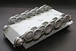
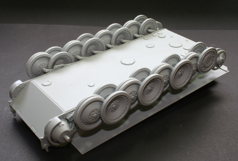
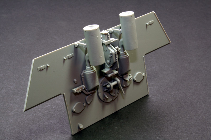
In these stages, you will install all the road wheels, and complete the rear hull wall. The road wheels, as said above, just need a wipe with some fine sandpaper, and some distressing of them with a scalpel blade wouldnt go amiss, depending on the state of the vehicle youre modelling. As also mentioned above, you get the option to install the last pair of road wheels as steel rimmed ones instead of rubber rimmed, so consult your references for the particular vehicle youre modelling. Dragon instructions are often complained about since people find them difficult. To an extent I can understand, but I think it is a little unjustified. In each stage, just make absolutely sure that you look at all the small exploded view boxes, where most of the choices for different options are given. Tempting as it is to just get on with the build, it does pay dividends to study the instructions closely before you do! In stage 4 there are different options again for the exhaust stacks, with regards to the muffler and the base of each exhaust. I went for the more common rounded bases and left off the muffler extensions. When complete the rear wall can be installed on to the hull. I cam across a problem here. There was a tiny gap running down either side of the rear wall where it meets the hull, and a larger one running along the bottom. Since I had done nothing to change the basic shape of the rear wall, or the hull, I can only suppose its a flaw in the kit. Its simple enough to fix, nevertheless it shouldnt be there. For the tiny gaps down either side I ran some super thin cement down the weld beads that are attaché to the rear wall, and after they had softened a little they could then be pushed into place with a fine, flat screwdriver. The gap along the bottom was filled with a thin styrene sheet, and then sanded smooth.Stages 6 to 8
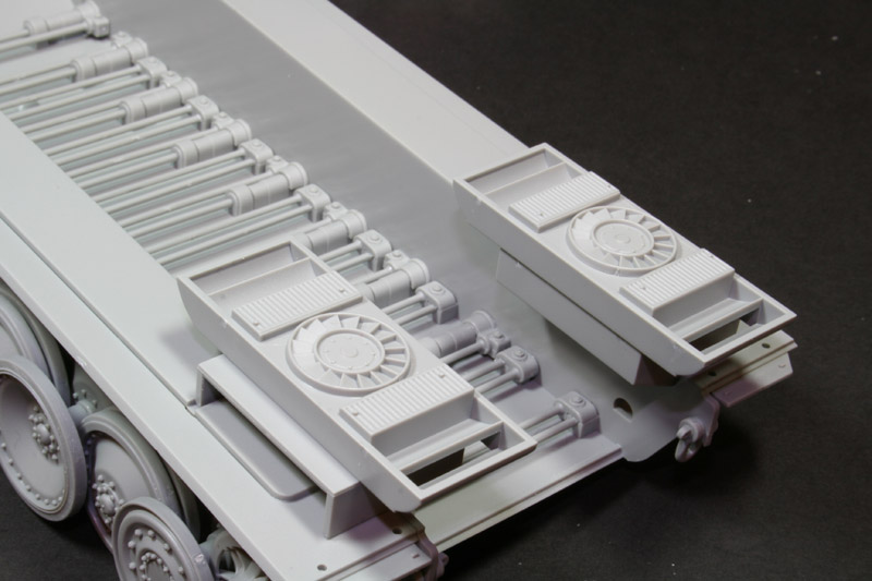
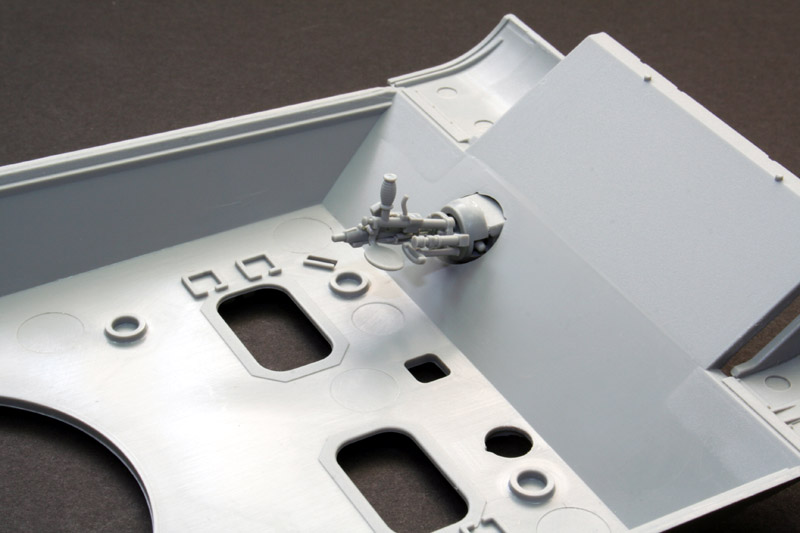
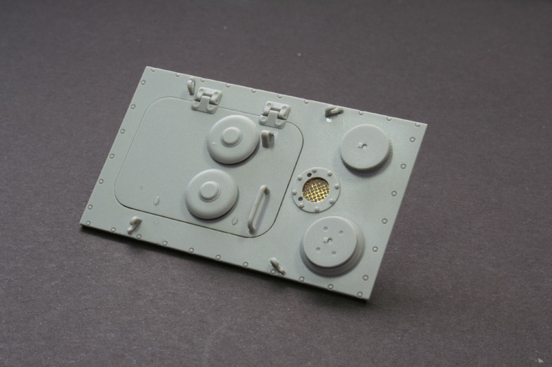
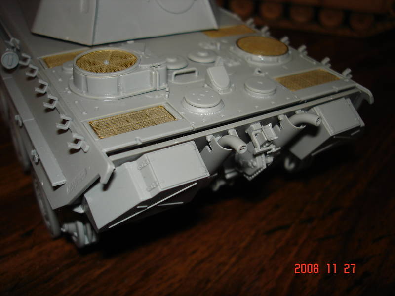
These stages deal with construction of the Mg34 for the for the co-driver, driver and co-drivers hatches, some periscope detail on the superstructure, and detailing the engine deck. Firstly, you have to decide whether or not youre actually going to use the machine gun, since not all would have had them, and Dragon do provide a blanking plate if you should choose not to use it. Having said that, its a beautiful little piece of moulding! Seven parts combine to make this little masterpiece, and unless youre going to leave the co-drivers hatch open , youre not going to see a thing! All the periscopes are supplied in clear styrene, as you would expect these days, and if you are going to leave the two front hatches open, there is some lovely detail provided for the hinges, springs etc. which again, can all be left off if the hatches are going to shown buttoned-up. All the external handles are provided as styrene, in keeping with Dragons aims in producing this kit, and there really is little need to replace them with wire, as long as youre careful when removing them from the sprue and cleaning them up. The drivers periscope again provides a choice of armoured covers, and make sure that you remove the square locating ribs around the housing for the oblique periscope on the superstructure deck. I didnt and had to remove the cover afterwards! You can also assemble the cylindrical cleaning rod case at this point. It comes in two halves, unlike the caption on the side which can mislead you into thinking its a one-piece affair. This will, of course, mean that youll have a seam to clean up. Use extra-thin cement, push the halves together, and leave it to dry for as long as you can, dont be tempted to try and clean up the seam until its thoroughly dry. When you sand it clean, use a thin strip of fine sandpaper, around the circumference, and you shouldnt have any visible seam afterwards. The instructions also state that the crow bar should be fixed to the top of the holding brackets, but it should be part K1 not K5 as the instructions say. Stage 8 is the detailing on the engine deck. Again, lots of choices. You can have two flush fans, or the left one raised and fitted with a heating duct to the crew compartment as it was on really late Gs. You can have that one with the fan closed off, or the fan stowed to one side. Its here you get to use the photo etched grills supplied with the kit.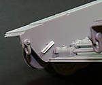 Idler adjustment
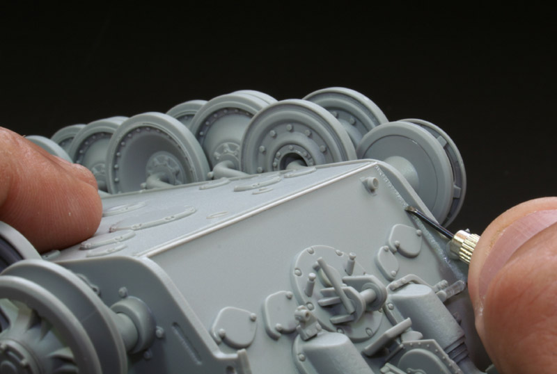
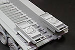
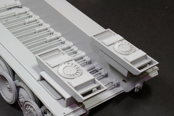
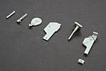 Parts for the Jack
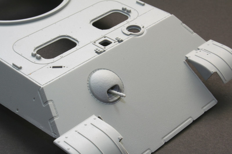
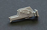 Completed Jack
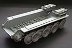
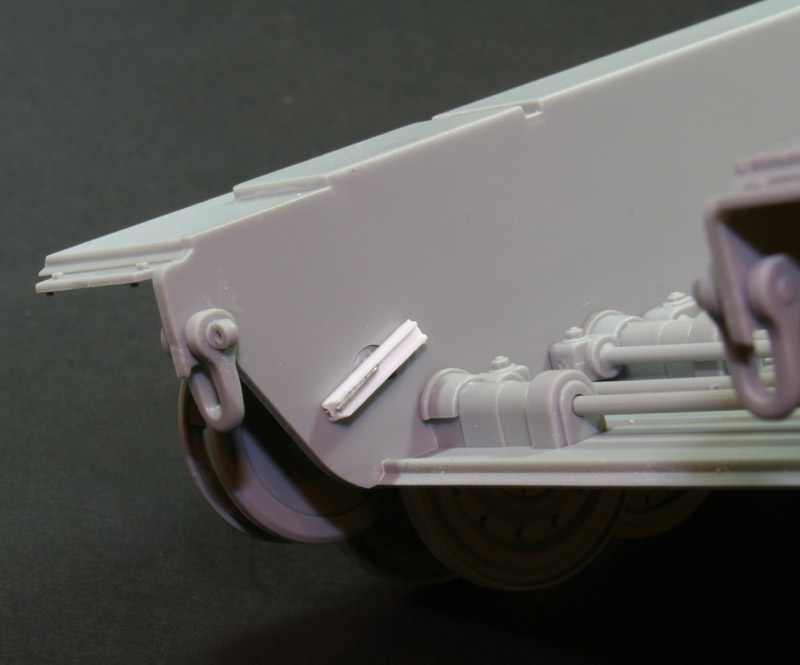
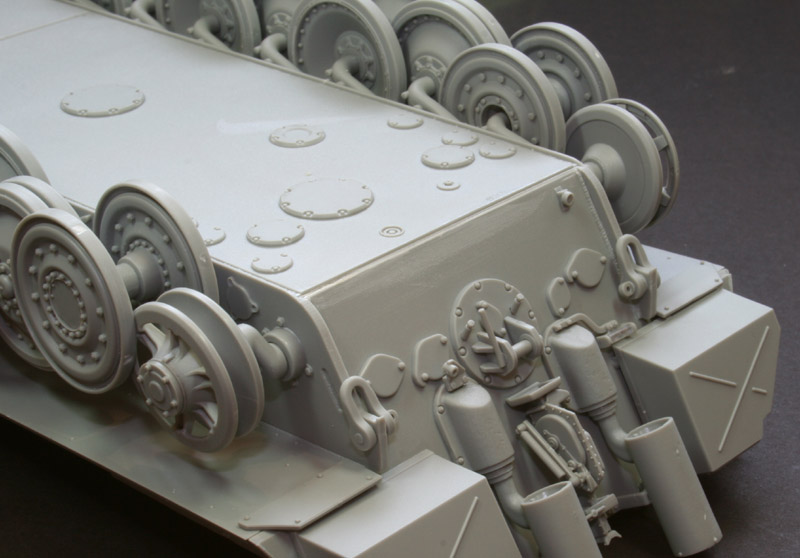
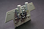 The rear wall
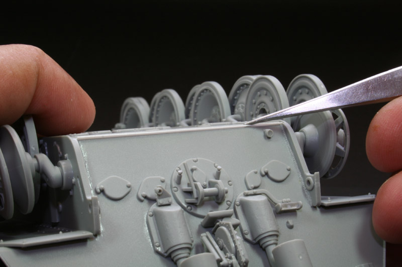
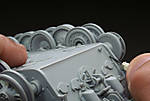 Fixing the weld beads


About the Author


Comments

Good build review Vinnie, two things that spring to mind after reading the review.
1.Are there no flame suppressing hoods for the exhaust stacks?
2. Does the kit include side skirts?
Regards from the Swamp
Hawkeye
JUL 15, 2006 - 10:53 PM

Ethan, hoods are supplied, but I didn't want them, it mentions this in the build, and as you can see from the review, no schurzen.
Vinnie
JUL 15, 2006 - 10:56 PM
Vinnie,
Great review! As always, I will be looking forward to your finished product.
I have a very basic question: Your builds always appear so clean (little if any glue marks). What type of glue do you use, and how do you apply it?
Thanks again,
irish
JUL 16, 2006 - 07:03 AM
once again, thanks for the building review Vinnie...
now i'm tempted to get one.... but i have acquire quite a number of large kits this few months....
but with that kind of price tag, i should be eating grass and dried scrubs....
JUL 16, 2006 - 08:39 AM
I've been building this kit. Your write up has been a tremendous help.
I ran into a small issue, on the back part of the rear deck I have a gap between the rear plate and the upper deck. I found in your photos that you have a plate that covers this area. There are clamp/hold-downs that bridges the rear deck and this plate. I checked the part trees and the instructions and I can not find it. It looks like, from your photo that this part was included in the kit. Yours does not look home made. What did you do?
LINK
NOV 27, 2008 - 08:46 AM

I could be completely wrong here, but it looks like your rear plate needs to go towards the front more. I don't believe there is an added piece, they just have to mate properly.
NOV 27, 2008 - 09:03 AM
Check his photos, towards the end and you can see the back with the panel. The clamp line up hole would make half the clamp hang over the edge.
NOV 27, 2008 - 09:16 AM
Like I said, I could be wrong, but looking at his photo and yours it appears that the rear plate needs to go forward and possibly raised.......

 Did you run into these same problems?
Anyway, I know nothing about this kit, just giving you something to check
Did you run into these same problems?
Anyway, I know nothing about this kit, just giving you something to check
Did you run into these same problems?
Anyway, I know nothing about this kit, just giving you something to check NOV 27, 2008 - 09:58 AM
Duh, I thought I had read his whole write-up. That's what I get for not reading it a second time. I know I built it correctly, everything else lined up perfectly. The it was very nice kit to build, except for a few instruction issues. This excellent write up solved most of the issues.
NOV 27, 2008 - 10:44 AM

Emmm, no point in asking for comments. The person who wrote this article is no longer either a member of this site nor has access to it. Why on earth a thread nearly two and a half years old gets resurrected is frankly beyond me...
Why don't you begin your OWN thread?
NOV 27, 2008 - 10:54 AM
Copyright ©2021 by Vinnie Branigan. Images and/or videos also by copyright holder unless otherwise noted. The views and opinions expressed herein are solely the views and opinions of the authors and/or contributors to this Web site and do not necessarily represent the views and/or opinions of Armorama, KitMaker Network, or Silver Star Enterrpises. All rights reserved. Originally published on: 2006-07-15 00:00:00. Unique Reads: 57100

WEB HOSTING BY


Copyright ©2021 Armorama and Kitmaker Network, a subsidiary of Silver Star Enterprises
All Rights Reserved. Please read our Conditions of Use and Privacy Policy.
All Rights Reserved. Please read our Conditions of Use and Privacy Policy.