

1⁄35Building Dragons 'Smart' Panther G
30
Comments
Stages 16 & 17
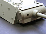
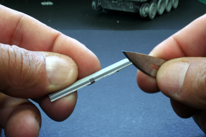
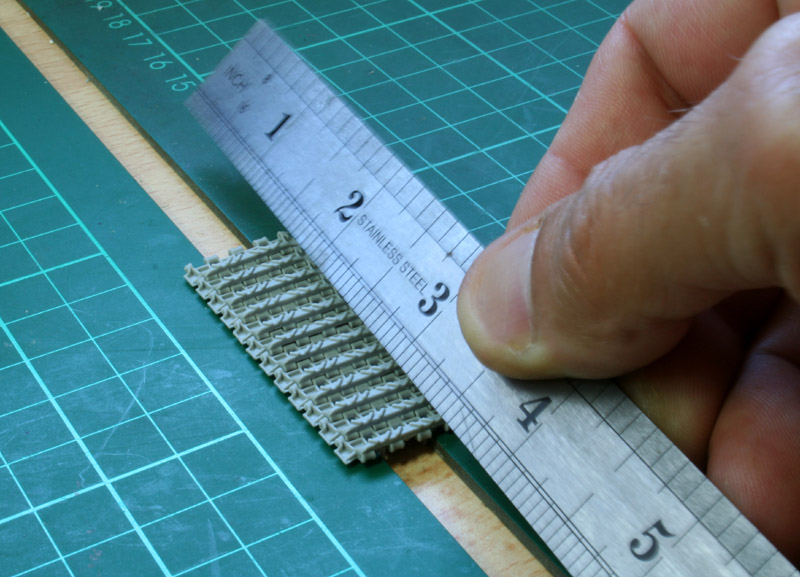
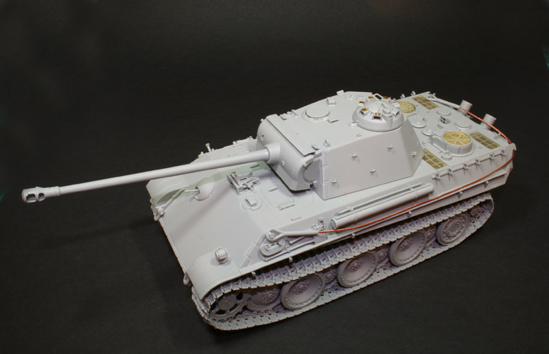
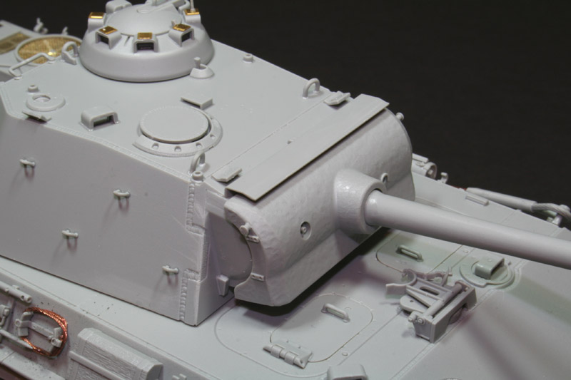
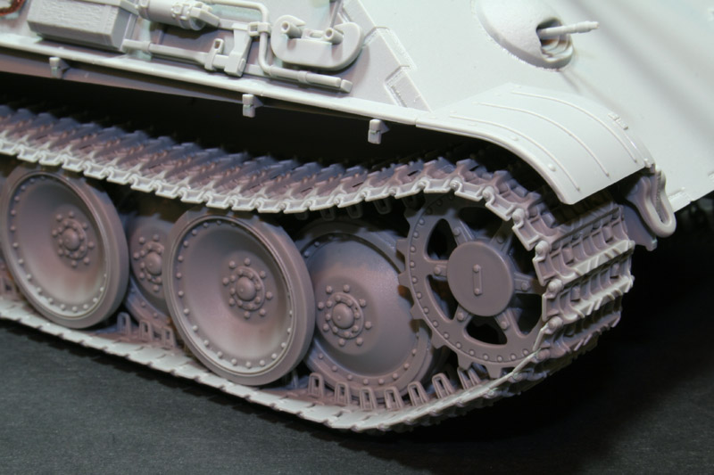
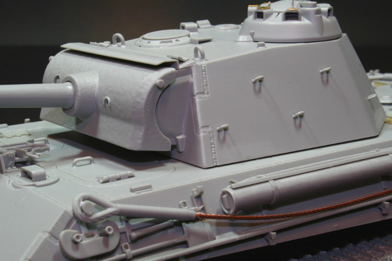
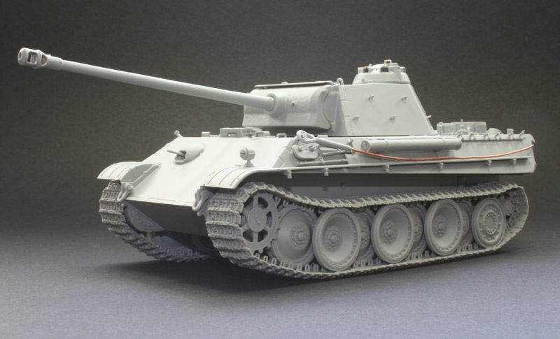
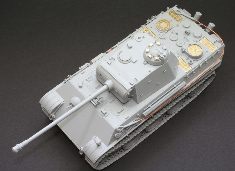
Completion of the turret and track installation. The first thing that hits you when you begin stage 16 is that there is no way on Earth that the mantlet guard, part B20, is going to fit. Its another case of the thickness of the part not being allowed for. The only way I could get it to look right, was to put the edge underneath the front edge of the turret roof. If you look really closely at stage 17, this is the way its shown. However, doing this throws out the front face of the turret when you come to fit it, as you can see from the photographs. The way I sorted it was to cut the lip off part B20, and then flush fit it to the front of the turret, allowing the mantlet assembly to fit properly as you can see in the pictures. You have the choice of an open or closed travel lock for the front of the deck, and then youll get to the tracks! Fitting the tracks is much, much easier if you dont fit the superstructure to the hull until after the tracks have been fitted. The tracks are wonderful! The detail on the guide horns is stunning, all injected tracks should be made like this. Your first job should be to construct the 16 links provided separately on the sprues for fitting around the drive sprockets. At first glance these look identical to the Magic tracks provided in the poly bag. However, the holes that the teeth on the drive sprocket will go through have been rounded off on these 16 links so that theyll sit properly, which the others will not do, should you use them instead. I constructed these 16 links and cemented them into position on the drive sprockets before assembling each of the two track runs. The instructions say that there are to be 181 links on either side. In the end I used 178 on the left and 177 on the right. Go figure! Each track run was made by clicking the links into place, the guide horns facing upwards. I then ran some super thin cement in between each link. I then created a space in between two cutting mats, and placed the track runs in this gap with the guide horns facing down. The top face of the run could then be flattened off with the help of a steel rule. Each run was allowed to dry for around 30 minutes, and then manipulated around the road wheels. Super thin cement was applied to where they made contact with the road wheels. Lastly, I substituted Karaya tow cables for the wire ones supplied by Dragon, I find these much easier to work with. There you have it .. Dragons new Smart Kit series Panther G. It is indeed, an easy model to make, despite some of the problems I ran into. The absence of all the usual Dragon goodies made it easier to construct, and it still ends up an accurate, great looking Panther G! Well done Dragon!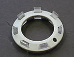
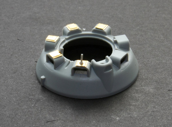
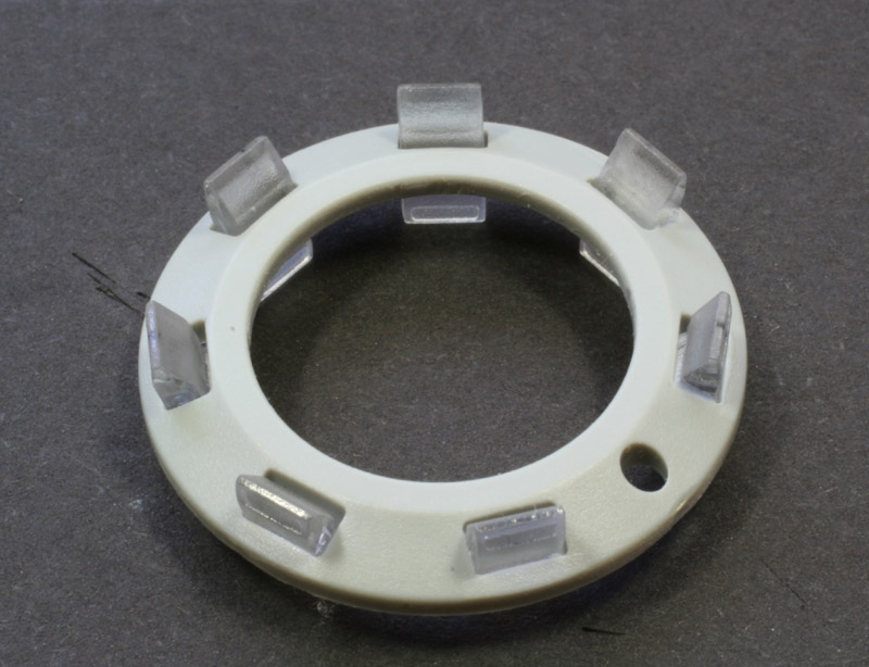
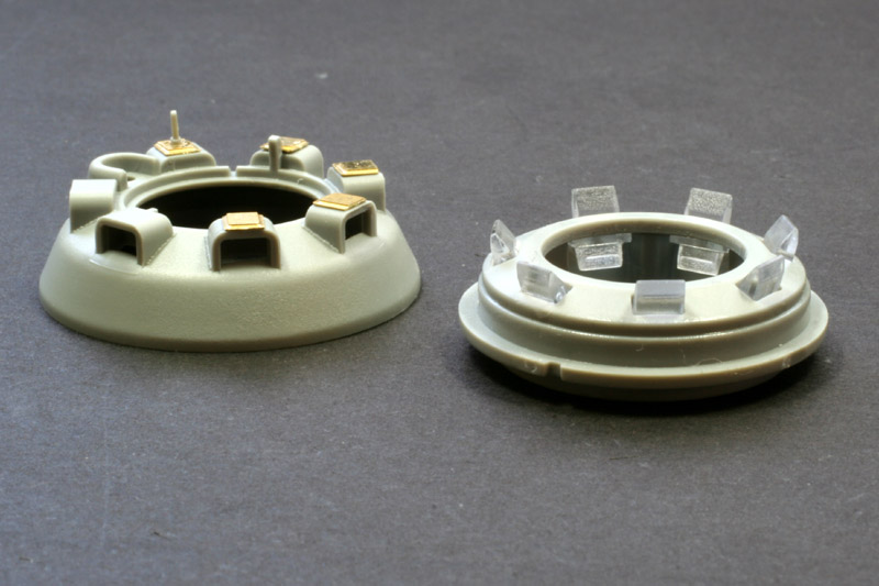
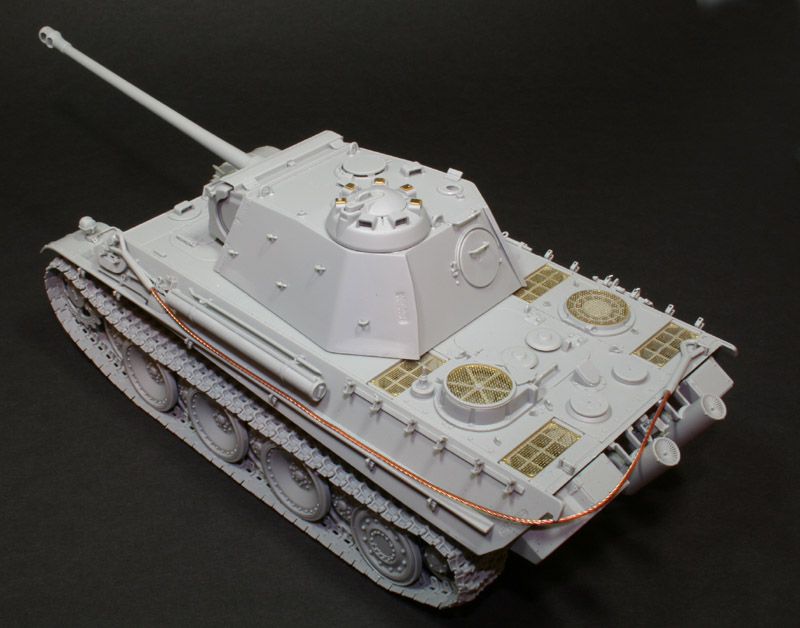
 Cupola
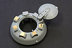
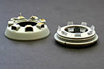
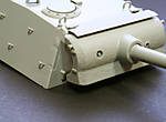
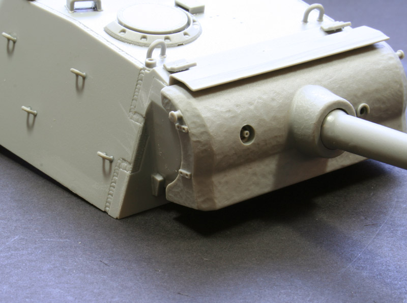
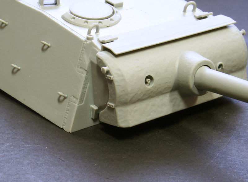
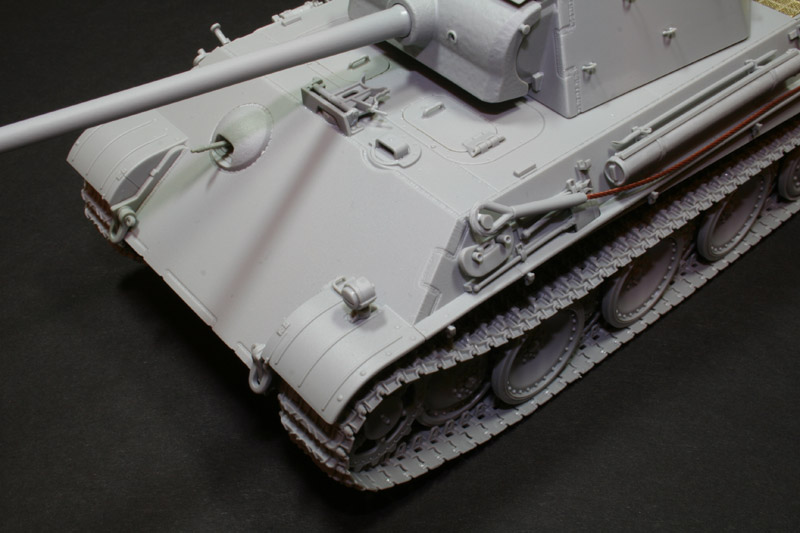
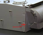 Misalignment of Manlet
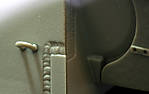 In close up
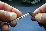
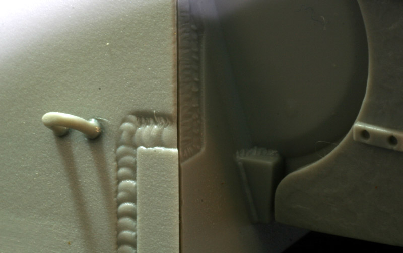
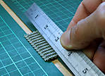 Flattening the tracks


About the Author


Comments

Good build review Vinnie, two things that spring to mind after reading the review.
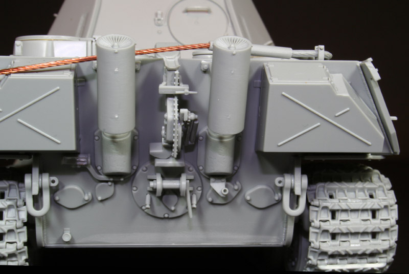
1.Are there no flame suppressing hoods for the exhaust stacks?
2. Does the kit include side skirts?
Regards from the Swamp
Hawkeye
JUL 15, 2006 - 10:53 PM

Ethan, hoods are supplied, but I didn't want them, it mentions this in the build, and as you can see from the review, no schurzen.
Vinnie
JUL 15, 2006 - 10:56 PM
Vinnie,
Great review! As always, I will be looking forward to your finished product.
I have a very basic question: Your builds always appear so clean (little if any glue marks). What type of glue do you use, and how do you apply it?
Thanks again,
irish
JUL 16, 2006 - 07:03 AM
once again, thanks for the building review Vinnie...
now i'm tempted to get one.... but i have acquire quite a number of large kits this few months....
but with that kind of price tag, i should be eating grass and dried scrubs....
JUL 16, 2006 - 08:39 AM

I've been building this kit. Your write up has been a tremendous help.
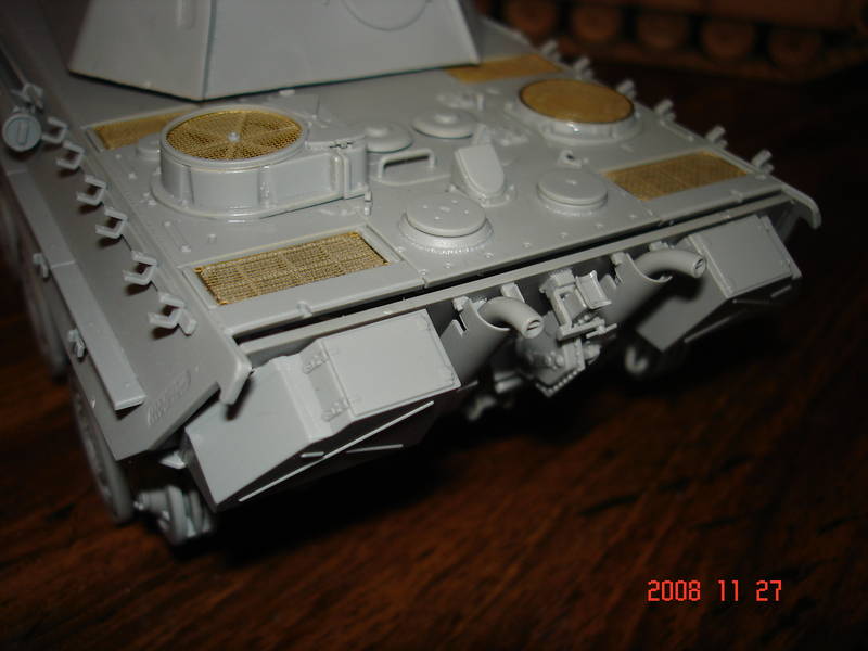
I ran into a small issue, on the back part of the rear deck I have a gap between the rear plate and the upper deck. I found in your photos that you have a plate that covers this area. There are clamp/hold-downs that bridges the rear deck and this plate. I checked the part trees and the instructions and I can not find it. It looks like, from your photo that this part was included in the kit. Yours does not look home made. What did you do?
LINK
NOV 27, 2008 - 08:46 AM

I could be completely wrong here, but it looks like your rear plate needs to go towards the front more. I don't believe there is an added piece, they just have to mate properly.
NOV 27, 2008 - 09:03 AM
Check his photos, towards the end and you can see the back with the panel. The clamp line up hole would make half the clamp hang over the edge.
NOV 27, 2008 - 09:16 AM
Like I said, I could be wrong, but looking at his photo and yours it appears that the rear plate needs to go forward and possibly raised.......

 Did you run into these same problems?
Anyway, I know nothing about this kit, just giving you something to check
Did you run into these same problems?
Anyway, I know nothing about this kit, just giving you something to check
Did you run into these same problems?
Anyway, I know nothing about this kit, just giving you something to check NOV 27, 2008 - 09:58 AM
Duh, I thought I had read his whole write-up. That's what I get for not reading it a second time. I know I built it correctly, everything else lined up perfectly. The it was very nice kit to build, except for a few instruction issues. This excellent write up solved most of the issues.
NOV 27, 2008 - 10:44 AM

Emmm, no point in asking for comments. The person who wrote this article is no longer either a member of this site nor has access to it. Why on earth a thread nearly two and a half years old gets resurrected is frankly beyond me...
Why don't you begin your OWN thread?
NOV 27, 2008 - 10:54 AM
Copyright ©2021 by Vinnie Branigan. Images and/or videos also by copyright holder unless otherwise noted. The views and opinions expressed herein are solely the views and opinions of the authors and/or contributors to this Web site and do not necessarily represent the views and/or opinions of Armorama, KitMaker Network, or Silver Star Enterrpises. All rights reserved. Originally published on: 2006-07-15 00:00:00. Unique Reads: 57100

WEB HOSTING BY


Copyright ©2021 Armorama and Kitmaker Network, a subsidiary of Silver Star Enterprises
All Rights Reserved. Please read our Conditions of Use and Privacy Policy.
All Rights Reserved. Please read our Conditions of Use and Privacy Policy.