

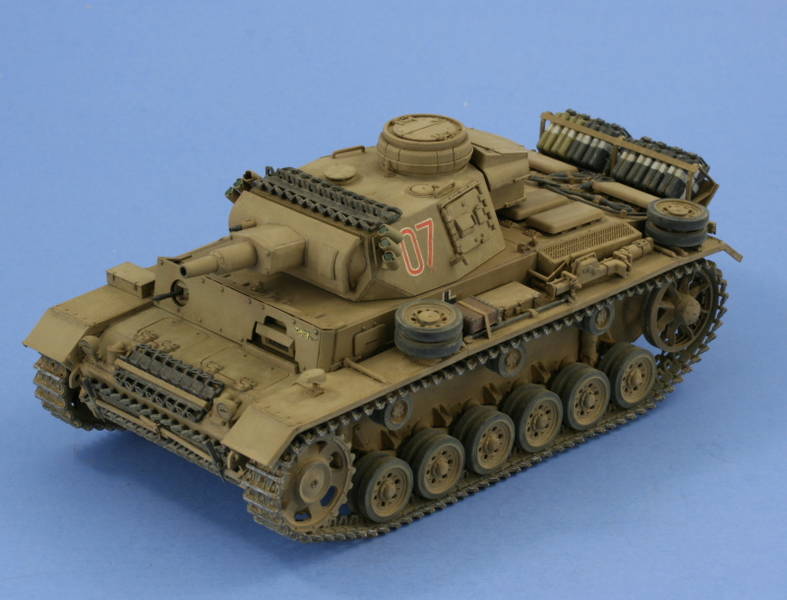
1⁄35Building DML's Pz.Kpfw. III Ausf N sPz.Abt. 501 Afrika
12
Comments
Introduction
The Pz.Kpfw. III family of vehicles has always fascinated me and the final variant, the Ausf. N, took the design as far as it could go. The N was a hybrid produced by taking the short-barreled 7.5cm KwK 37 L/24 gun that had been used with the Pz.Kpfw. IV chassis and mounting it into converted Ausf. J, L, and M production vehicles. Over 660 were produced, mainly from Ls, which DMLs kit #6431 Pz.Kpfw. III Ausf. N sPz.Abt. 501 Afrika produces and is the subject of this build.Lower hull and suspension
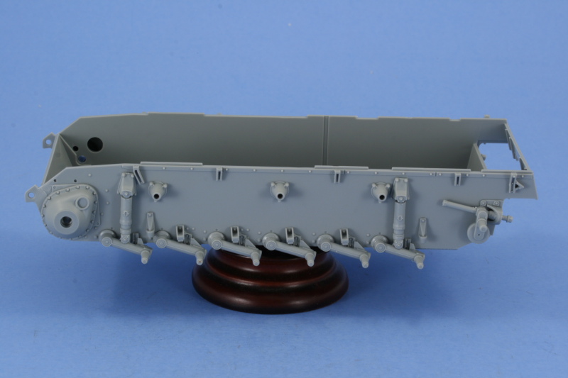
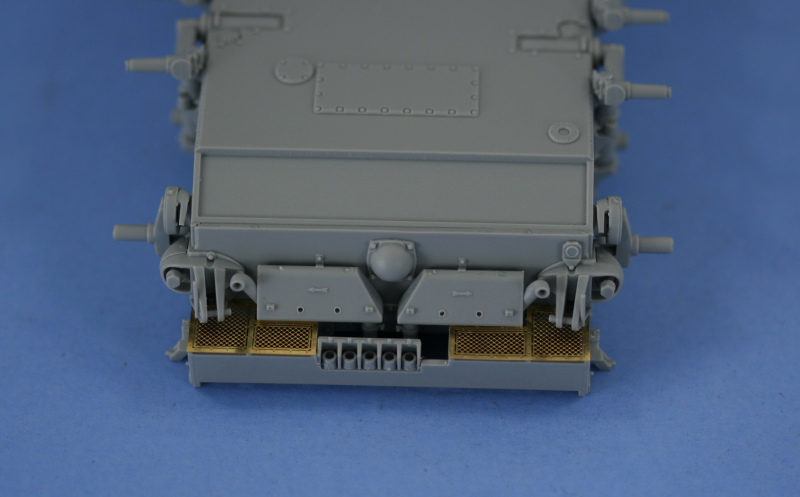
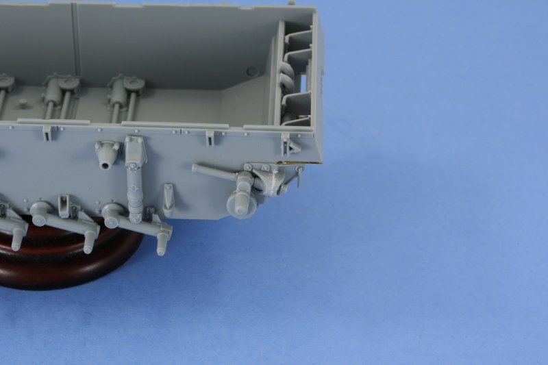
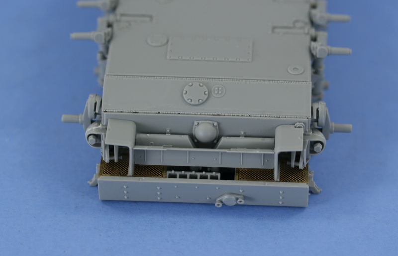
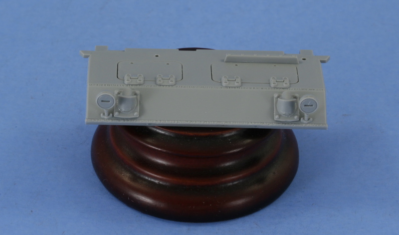
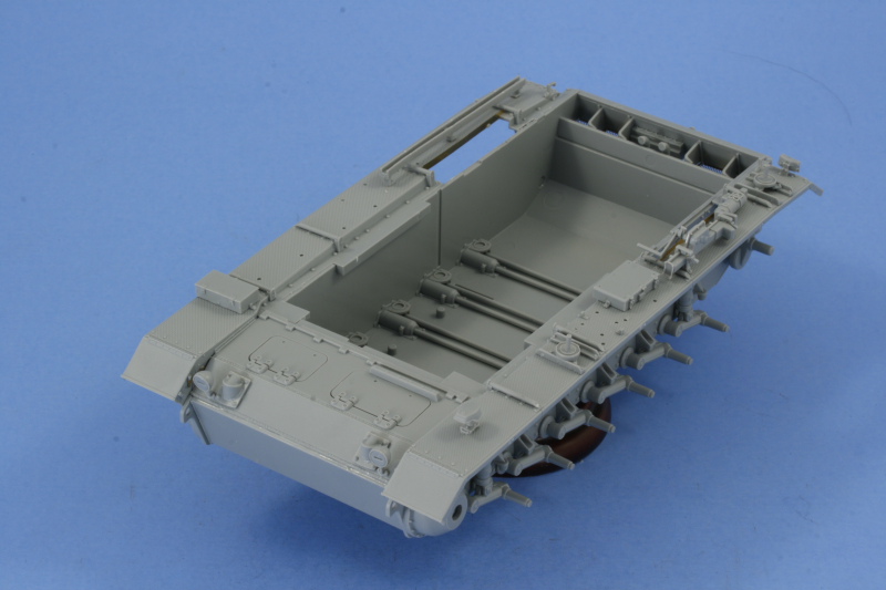
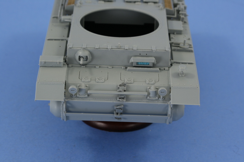
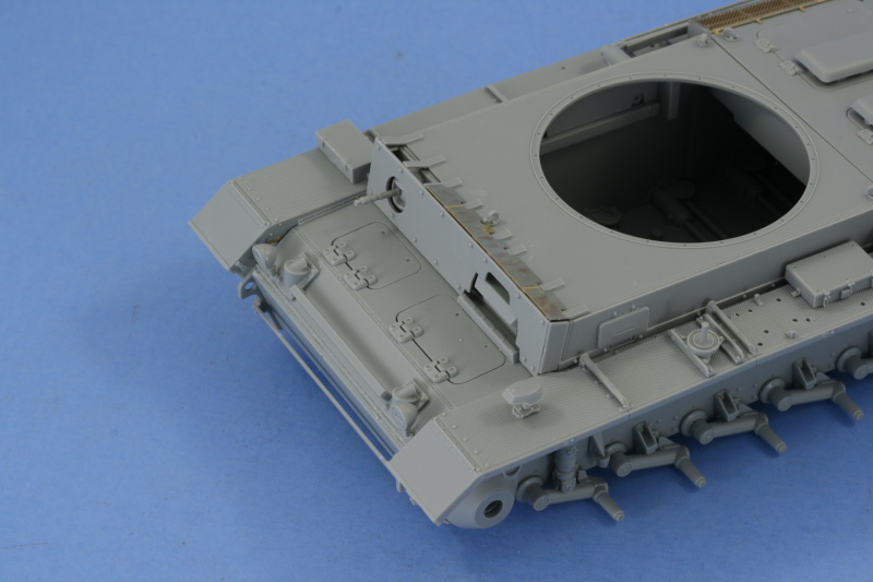
The build began with the running gear. The idlers were assembled along with their PE inserts as were the sprockets and return rollers. Since the road wheel halves will be painted separately, they had their mold seams carefully removed using a set of sanding twigs but werent assembled yet. The lower hull suspension elements were installed next along with the torsion bars and idler arms fixed into position. The idler mounts, due to the nature of their design, are fixed into position and are not moveable, so these were installed along with the final drive housings to complete this area. The rear hull area with the rear plate including the towing eyes, exhausts, and intake deflector, and PE vent screens came next. The plate was assembled first with its details and then installed into the lower hull. I discovered it probably wouldve been better to wait to install the idler mounts since at this point vs. earlier since they integrate in with the towing eyes on the plate and a very small gap appeared that needed putty as a result. The PE intake screens followed, using just a small amount of liquid glue to secure them in place. These screens rest on small raised tabs vs. sitting flush on the hull extension, so its important to get them into proper position to avoid issues, so I avoided using CA. Next came the installation of the deflector screens, the rear hull plate with the armored cover for the crank starter port, and the angled lower rear hull plate. The weld seam molding on that plate didnt quite have enough substance to mate up properly with the lower hull, so once the glue had dried a little putty was employed here as well.Fenders and Upper Hull
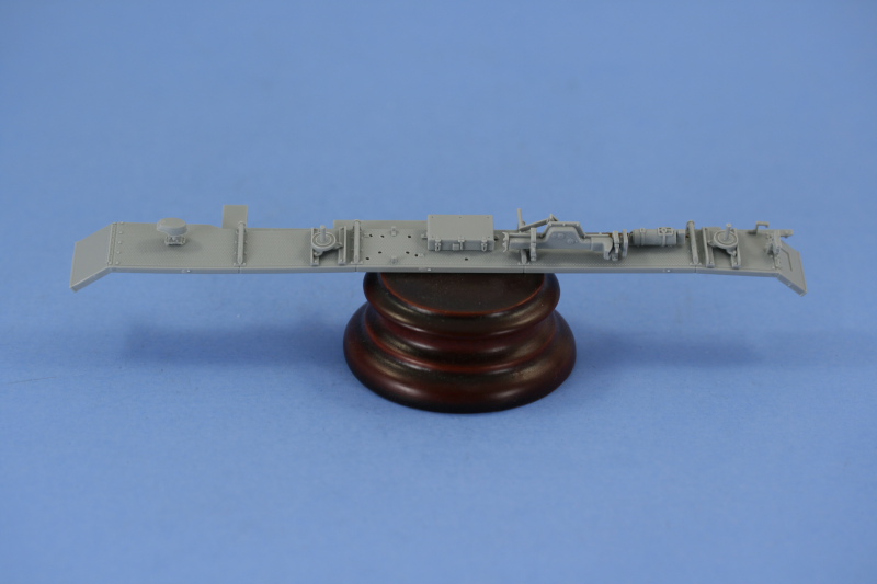
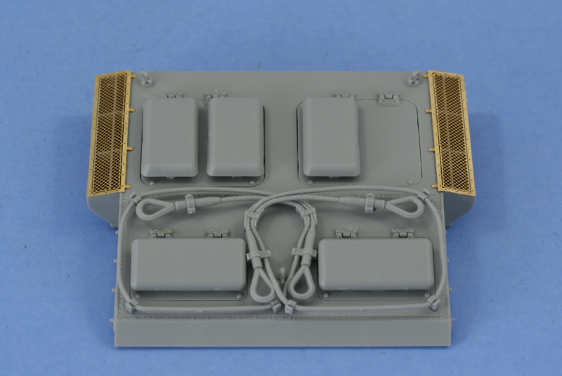
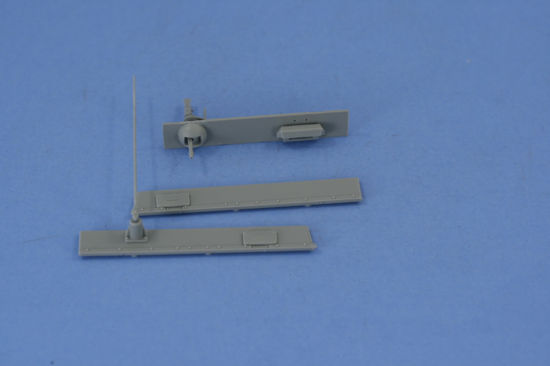
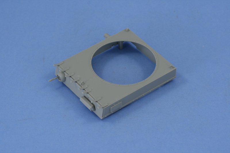
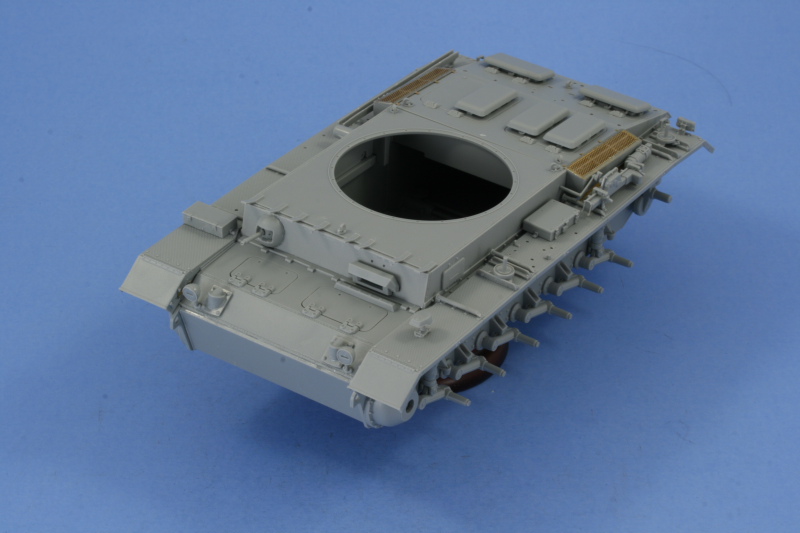
The modular design that DML employs on this kit means that the upper hull and fenders are constructed and joined together in a modular fashion to produce the upper hull. Starting with the fenders, the left side fender received its supports along with the spare wheel mounts, front Notek light, tool box, jack, fire extinguisher, and rear Notek light as well as the rear mud flap. The pioneer tools were left off for now to better facilitate detail painting later on and the right side fender was much simpler vs. the left. It received its supports along with the small box at the front, the wooden antenna tray frame, and the rear fender. The rear engine deck called for the installation of the armored engine deck hatches and vents and the side air intakes and their corresponding PE screens. The PE screens need to be bent slightly at the edges that mate up to the hull and this was easily accomplished with a pair of needle nose pliers prior to installation. I opted for the molded-in tow cables and brackets and test fit their alignment to be sure they could be painted and detailed later. Constructing the upper hull box requires that the individual panels first receive some attention before they are combined along with the foundation to create the upper hull assembly. The roof plate had 4 molded on posts that dont belong on the Ausf N and these were removed and the lifting eyes installed. The left side plate had the gunners port installed along with the radio antenna mast and the antenna arm dry-fitted. The right side plate only required the drivers side vision port to be installed and I opted to keep it in the closed position. The front plate MG34 was assembled and installed along with the drivers armored visor and armored glass block. All of the panels were then glued in place with the foundation part A61 using standard glue to get them into place followed by liquid glue applied around the weld seams with a detail brush and careful use of finger pressure to the join areas to get everything together. The glacis plate followed with its details. The two front hatches were installed along with the front head lights with their black-out covers. While the instructions called for the lower front hull plate, D11, to be installed back at the beginning, Id held off until this point to insure it and the glacis plate matched up properly. Both plates were then installed to the lower hull along with the fenders, using the same combination of standard glue to position and liquid glue at the weld seams to complete the joins. The fenders were a little tricky due to the limited surface area at some places along the hull, but worked out eventually. Once these were set, then the hull superstructure and rear engine deck were added. The hull details were completed by installing the spare track holders to the nose and glacis plates. I used reference photos of Red 07, the vehicle Id decided to model, to determine which type of spare holder was needed on the glacis since 3 different types are provided in the kit. I also test fit a couple of the kits Magic individual links just to be sure I could add those later. The spaced hull armor plates were also installed at this point along with the PE top plate to complete the upper hull assembly.


About the Author


FROM: TEXAS, UNITED STATES
Like many, I started out in the hobby as a kid building airplanes to hang from my bedroom cieling. I took a long break from the hobby, returning in 2001 with an interest in armor inspired mostly by online gaming. WW2 armor, 1/35 scale, is my preferred genre with a special taste for the stranger vehi...
Comments

Your tank came out incredible!! I enjoyed watching your build from beginning to end and look forward to seeing more of your builds in the future. I learned a few things also,thanks Bob
MAR 17, 2008 - 05:26 PM
Great build - now where is that Tiger I that goes along with it
Thanks for sharing
MAR 17, 2008 - 10:21 PM

Thanks Bob for the comments, glad it will be of some help to you.
Jesper,
The box-art has an interesting possibility for pairing it up with some Tiger 1s, almost certain someone will do the dio of it in the near future.
MAR 18, 2008 - 06:29 AM

Nice finish Bill. Once again can I see that undreside now that it's finished? I am rounding the corner in assembly on mine. Sure wish my camera and my computer were working.
MAR 18, 2008 - 07:32 AM
James,
Not sure if these will help you more than the other shots, but here you go. I can't turn it all the way upside down like I did in the WIP photos due to limited handling surfaces.


MAR 18, 2008 - 01:31 PM


Outstanding Build ! I always seem to learn somthing about the hobby from viewing everyones projects. Very Cool Panzer III. Thanks for sharing.
APR 12, 2008 - 06:35 AM
Thanks milvehfan. I agree about reading about other people's projects, always pick up little things here and there by seeing how others tackle verious issues or approach things. Virtually all of my exposure to model-related subjects is via the Internet and can't tell you how invaluable a resource it is for past, present, and future learning and evolution. Someone's always coming up with a newer/better way to do things and when they share that in a community such as Armorama, everyone benefits. I try to do the same thing with my work even if sometimes it's a better example of how NOT to do something.
APR 12, 2008 - 09:37 AM
Copyright ©2021 by Bill Plunk. Images and/or videos also by copyright holder unless otherwise noted. The views and opinions expressed herein are solely the views and opinions of the authors and/or contributors to this Web site and do not necessarily represent the views and/or opinions of Armorama, KitMaker Network, or Silver Star Enterrpises. All rights reserved. Originally published on: 2008-03-16 00:00:00. Unique Reads: 35532

WEB HOSTING BY


Copyright ©2021 Armorama and Kitmaker Network, a subsidiary of Silver Star Enterprises
All Rights Reserved. Please read our Conditions of Use and Privacy Policy.
All Rights Reserved. Please read our Conditions of Use and Privacy Policy.